


Price - $3.00
INSTALLATION, OPERATING AND
SERVICE INSTRUCTIONS FOR
RSA BOILERS


 1
1


IMPORTANT INFORMATION - READ CAREFULLY
All boilers must be ins ta lled in accordance with Nationa l, State and Local Plumbing,
He ating and Electrical Codes and the regulations of the serving utilities. These Codes and Regulations may differ from this instruction manua l. Authorities hav ing jurisdiction should be consulted before installa tions are made.
In a ll cases , re fe re nc e should be made to the following Standards:
All wiring on boilers installed in the USA shall be made in accorda nce with the National Electrical Code and/or Loc al Regulations.
All wiring on boilers installed in Canada shall be made in ac corda nce with the Canadian Electrical Code and/or Loc al Regulations.
USA BOILERS
A.Current Edition of American National Standard ANSI/NFPA 31, “Installation of Oil Burning Equipment”, for recommended installation practices.
B.Current Edition of American National Standard ANSI/NFPA 2 11, “Chimne ys, Firepla ces, Vents, and Solid Fuel Burning Appliances”, For Venting requirements.
C.Current Edition of American Society of Mechanical Engineers ASME CSD-1, "Controls and Safety Devices for Automatically Fired Boilers", for assembly and operations of controls
and safety devices.
CANADIAN BOILERS
A.Current Edition of Canadian Standards Association CSA B139, "Installation Code for Oil Burning Equipment", for recommended Installation Practices.
The following terms are used throughout this manual to bring attention to the presence of hazards of various risk levels, or to important information concerning product life.
DANGER
Indicates an imminently ha zardous situation w hich, if not avoided, will re sult in death, serious injury or substantial property damage.
CAUTION
Indic ates a potentially ha zardous situation which, if not av oided, may result in modera te or minor injury or property damage.
WARNING
Indic ates a potentially ha zardous situation which, if not avoide d, could re sult in death, serious injury or substantial property damage.
NOTICE
Indicates spe cial instructions on installation, operation, or ma intenance w hich are importa nt but not related to personal injury ha zards.
NOTICE
This boiler has a limited warranty, a copy of w hich is printed on the back of this manual.
It is the responsibility of the installing contractor to see that all controls are correctly installed and are operating properly when the installation is complete. The warranty for this boiler is valid only if the boiler has been installed, maintained and operated in accordance with these instructions.
2
DANGER
DO NOT store or use gasoline or other flammable vapors or liquids in the vicinity of this or any other appliance.
WARNING
Improper installation, adjustment, alteration, servic e or mainte na nce can cause property damage, personal injury or loss of life. Failure to follow all instructions in the proper order can cause personal injury or death. Read and understand all instructions, inc luding all those containe d in compone nt manufac turers manuals w hich are prov ided with the appliance before installing, starting-up, opera ting, maintaining or servicing this applia nce. Keep this manual and lite rature in legible condition and posted near appliance for reference by owner and service technic ian.
This boiler requires regular maintenance and service to operate safely. Follow the instructions contained in this manual. Installation, maintenance, and service must be performed only by an experienced, skilled and knowledgeable installer or service agency. All heating systems should be designed by c ompetent contrac tors and only persons k nowledge able in the la yout and installa tion of hydronic heating systems should attempt installation of any boiler. It is the responsibility of the installing contractor to see that all controls are correctly installed and are operating properly w hen the installation is completed. Installation is not complete unless a pressure relief valve is installed into the tapping located on top of appliance - See Section III of this manual for details.
This boiler is not suitable for installation on c ombustible flooring, unless installed with a combustible floor shield (available at extra cost). Do not ins tall boiler on carpeting.
Do not tam per with or alter the boiler or controls. Re tain your cont ra ctor or a compet ent se rv ice man to assure that th e unit is p ro perly adjus ted an d main taine d.
Have Firetube s cleane d at leas t once a year - prefe rably at the start o f the he ating sea son to re move soot a nd sca le. The inside of combustion cha mber sho uld also be cle aned and ins pecte d at the same time .
Have Oil Burner and Controls ch ecke d at leas t once a ye ar or as may be nec ess itate d. Do not operate unit w ith jumpere d or abs ent con tro ls or safety devices .
Do no t operate unit if any control, switc h, c omponent, or dev ice has b een s ubjec t to w ate r.
3

WARNING
Appliance materials of construction, products of combustion and the fuel contain alumina, silica, he av y me tals, carb on mon oxide, nitrogen oxides , a ldehyd es a nd/or oth er tox ic or harm ful substances which can cause death or serious injury and which are known to the state of California to cause cancer, birth defects and other reproductive harm. Always use proper safety clothing, respirators and equipment when servicing or working nearby the appliance.
This boiler contains very hot water under high pressures. Do not unscrew any pipe fittings nor attempt to disconnect any components of this boiler without positively assuring the water is cool and has no pressure. Always w ear protective clothing and equipment when installing, starting up or servicing this boiler to prevent scald injuries. Do not rely on the pressure and temperature gauges to determine the temperature and pressure of the boiler. This boiler contains components w hich become very hot w hen the boiler is operating. Do not touch any components unless they are cool.
This appliance mus t be properly v ented and connected to an approved vent system in good condition. Do not ope rate boiler with the absence of an unapproved ve nt s ystem.
This boiler needs fresh air for safe operation and must be installed so there are provisions for adequate combustion and ventilation air.
The interior of the venting and air intake systems must be inspected and cleaned before the start of the heating season and should be inspected periodically throughout the heating season for any obstructions. Clean and unobstructed venting and air intake systems are necessary to allow noxious fumes that could cause injury or loss of life to vent safely and will contribute toward maintaining the boiler's efficiency.
This boiler is supplied with controls which may cause the boiler to shut down and not re-start without service. If damage due to frozen pipes is a possibility, the heating system should
not be left unatttended in cold weather; or appropriate safeguards and alarms should be installed on the heating system to prevent damage if the boiler is inoperative.
This boiler is designed to burn No. 2 fuel oil only. Do not use gasoline, crankcase drainings, or any oil containing gasoline. Never burn garbage or paper in this boiler. Do not convert to any solid fuel (i. e. wood, coal) or gaseous fuel (i. e. natural gas, LP/propane). All flammable debris, rags, paper, wood scraps, etc., should be kept clear of the boiler at all times. Keep the boiler area clean and free of fire hazards.
Do not operate boiler on combustible floor without a factory supplied floor shield. Concrete over wood joists is considered combustible flooring. Do not operate on masonry floors, which may contain moisture.
4

Tables of Contents
I. |
Pre-Installation ..................................... |
7 |
VI. |
Oil Piping ........................................... |
28 |
II. |
Knockdown Boiler Assembly ............... |
9 |
VII. System Start-Up .................................. |
30 |
|
III. Water Piping and Trim ...................... |
12 |
VIII. Service and Cleaning .......................... |
36 |
||
IV. |
Venting ............................................... |
18 |
IX. |
Repair Parts ........................................ |
38 |
V.Electrical and Sequence of Operation 20
Figure 1: RSA Packaged Boiler (RSA85 / RSA135)
5

Figure 1A: RSA Packaged Boiler (RSA170 / RSA285)
Boiler |
Bare Boiler |
Minimum Chimney Sizes |
Water |
Approx. |
|||
|
|
||||||
Model |
In. x In. x Ft. |
In. (dia.) x Ft. |
Capacity |
Shipping |
|||
Assembly |
|||||||
Num ber |
(height) |
(height) |
Gallons |
Weight |
|||
|
|||||||
|
|
|
|
|
|||
|
|
|
|
|
|
|
|
RS A170 |
WV-29-10 |
8 x 8 x 20 |
7" x 20' |
42.6 |
600 |
lb. |
|
|
|
|
|
|
|
|
|
RS A195 |
WV-29-13A |
8 x 8 x 20 |
8" x 20' |
39.9 |
630 |
lb. |
|
|
|
|
|
|
|
|
|
RS A240 |
WV-29-16A |
8 x 12 x 20 |
8" x 20' |
37.3 |
660 |
lb. |
|
|
|
|
|
|
|
|
|
RS A285 |
WV-29-19A |
8 x 12 x 20 |
9" x 20' |
34.6 |
690 |
lb. |
|
|
|
|
|
|
|
|
|
6
I. Pre-Installation
A. INSPECT SHIPMENT carefully for any signs of damage.
1.ALL EQUIPMENT is carefully manufactured, inspected and packed. Our responsibility ceases upon delivery of the crated boiler to the carrier in good condition.
2.ANY CLAIMS for damage or shortage of shipment must filed immediately against the carrier by the consignee. No claims for variances from, or shortage in orders, will be allowed by the manufacturer unless presented within sixty (60) days after receipt of goods.
B. LOCATE BOILER in front of final position before removing crate.
1.LOCATE so that smoke pipe connection to chimney will be short and direct. BOILER IS NOT SUITABLE FOR INSTALLATION ON COMBUSTIBLE FLOOR unless combustible floor shield,
supplied by Burnham, is used. DO NOT install on carpeting.
2.FOR BASEMENT INSTALLATION, provide a solid base, such as concrete, if floor is not level, or if water may be encountered on floor around boiler.
3.PROVIDE SERVICE CLEARANCE of at least 48” from the front of the jacket for servicing of burner and removal of tankless heater.
For minimum clearances to combustible materials. See Figure 2.
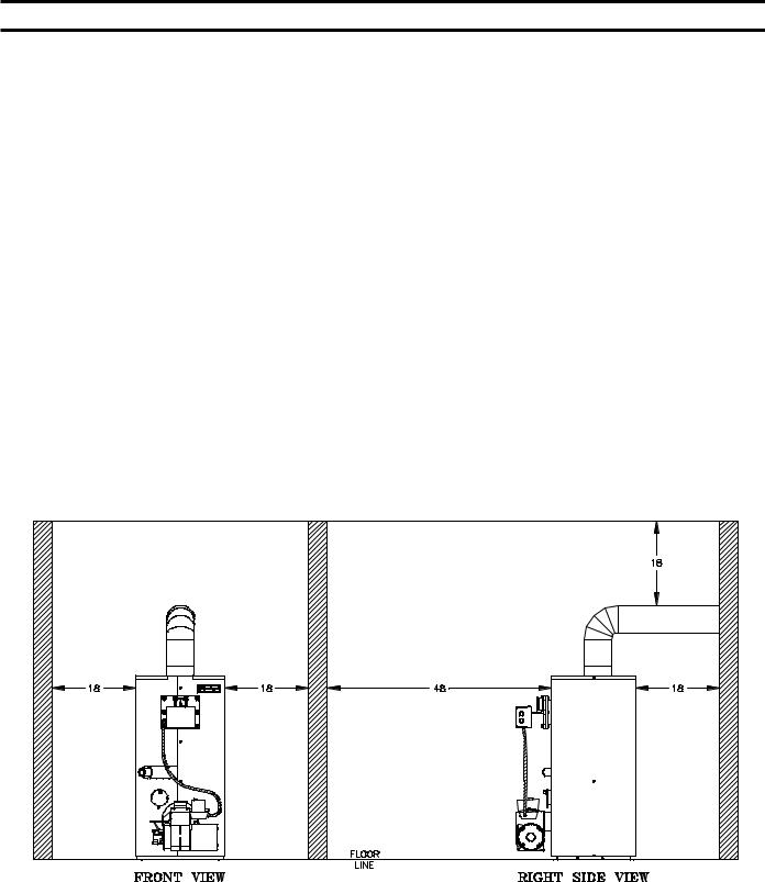
Figure 2: Minimum Clearances to Combustible Materials
NOTE:
1.Listed clearances comply with American National Standard ANSI/NFPA 31, Installation of Oil Burning Equipment.
2.RSA boilers can be installed in rooms with clearances from combustible material as listed above. Listed clearances can not be reduced for alcove or closet installations.
3.For reduced clearances to combustible material, protection must be provided as described in the above ANSI/NFPA 31 standard.
7
C. PROVIDE AIR SUPPLY AND VENTILATION to accommodate proper combustion. If natural ventilation is inadequate, provide a screened opening or duct from the boiler room to the outside. The opening or duct must be sized so the boiler input will not exceed 4,000 BTUH/Sq. In. of free area. If other air consuming appliances are near the boiler, the air inlet should be larger. Consult respective manufacturers.
D. VENTILATION AIR must be provided to maintain the ambient temperature at safe limits. Local and national codes may apply and should be referenced.
1.In unconfined spaces (basement) in buildings of conventional frame, brick, or stone construction, infiltration normally is adequate to provide air for ventilation.
2.In confined spaces, two permanent openings, one near the top of the enclosure and one near the bottom, shall be provided. Each opening shall have a free area of not less than 1 sq. inch per 1000 BTUH of the total input of all appliances in the space.
3.PROVIDE COMBUSTION AND VENTILATION AIR. Local code provisions may apply and should be referenced.
A.Determine volume of space (boiler room). Rooms communicating directly with the space in which the appliances are installed, through openings not furnished with doors, are considered a part of the space.
Volume(ft3) = Length(ft) x Width(ft) x Height(ft)
B.Determine total input of all appliances in the space. Add inputs of all appliances in the space and round the result to the nearest 1000 BTU per hour.
C.Determine type of space. Divide Volume by total input of all appliances in space. If the result is greater than or equal to 50 ft3/1000 BTU per hour, then it is considered an unconfined space. If the result is less
than 50 ft3/1000 BTU per hour then the space is considered a confined space.
D.For boiler located in an unconfined space of a conventionally constructed building, the fresh air infiltration through cracks around windows and doors normally provides adequate air for combustion and ventilation.
E.For boiler located in a confined space or an unconfined space in a building of unusually tight construction, provide outdoor air with the use of two permanent openings which communicate directly or by duct with the outdoors or spaces (crawl or attic) freely communicating with the outdoors. Locate one opening within 12 inches of top of space. Locate remaining opening within 12 inches of bottom of space. Minimum dimension of air opening is 3 inches. Size each opening per following:
1.Direct communication with outdoors. Minimum free area of 1 square inch per 4,000 BTU per hour input of all equipment in space.
2.Vertical ducts. Minimum free area of 1 square inch per 4,000 BTU per hour input of all equipment in space. Duct cross-sectional area shall be same as opening free area.
3.Horizontal ducts. Minimum free area of 1 square inch per 2,000 BTU per hour input of all equipment in space. Duct cross-sectional area shall be same as opening free area.
Alternate method for boiler located within confined space. Use indoor air if two permanent openings communicate directly with additional space(s) of sufficient volume such that combined volume of all spaces meet criteria for unconfined space. Size each opening for minimum free area of 1 square inch per 1,000 BTU per hour input of all equipment in spaces, but not less than 100 square inches.
F. Louvers and Grilles of Ventilation Ducts
1.All outside openings should be screened and louvered. Screens used should not be smaller than 1/4 inch mesh. Louvers will prevent the entrance of rain and snow.
2.Free area requirements need to consider the blocking effect of louvers, grilles, or screens protecting the openings. If the free area of the louver or grille is not known, assume wood louvers have 20-25 percent free area and metal louvers and grilles have 60-75 percent free area.
3.Louvers and grilles must be fixed in the open position, or interlocked with the equipment to open automatically during equipment operation.
8

II. Knock-Down Boiler Assembly
A. REMOVAL OF BOILER.
1.Remove, all boiler to skid, hold down fasteners. Refer to Figure 3.
2.Carefully walk boiler to the edge of skid. Tilt the boiler back, allowing an edge to rest on the floor, and remove the skid.
Figure 3: Base on Skid
B. TEST HEAT EXCHANGER FOR LEAKS before proceeding with jacket assembly. Heat exchanger, canopy, and base are preassembled.
1.Install pressure gauge supplied, a hose to the city water and a valve in the supply tapping. Plug remainder of tappings.
2.Fill boiler with water and apply a pressure of at least 10 psig but no more than 30 psig.
H.INSTALLING THE JACKET
1.Before jacket can be secured to boiler assembly tankless heater coil or blank plate must be attached. Using rubber gasket and bolts provided secure heater coil or blank plate to boiler extension by inserting the bolts from the backside of the extension. Refer to Figure 4.
9

Figure 5: Burner Mounting
10
11
Figure 6: RSA Jacket Assembly
III. Water Piping and Trim
WARNING
Failure to properly pipe boile r may re sult in improper ope ration and da mage to boiler or structure .
Oxyge n c onta mination of boiler water will cause corrosion of iron a nd s te el boiler
c ompone nts , and can lead to boiler failure. Burnham's Standard Warranty does not cover problems caused by oxy ge n contamination of boiler water or scale (lime ) build-up c aused by freque nt addition of w ater.
A.Design a piping system and install boiler which will prevent oxygen contamination of boiler water and frequent water additions.
1.There are many possible causes of oxygen contamination such as:
a.Addition of excessive make-up water as a result of system leaks.
b.Absorption through open tanks and fittings.
c.Oxygen permeable materials in the distribution system.
2.In order to insure long product life, oxygen sources should be eliminated. This can be accomplished by taking the following measures:
a.Repairing system leaks to eliminate the need for addition of make-up water.
b.Eliminating open tanks from the system.
c.Eliminating and/or repairing fittings which allow oxygen absorption.
d.Use of non-permeable materials in the distribution system.
e.Isolating the boiler from the system water by installing a heat exchanger.
WARNING
System supply and return piping must be connected to correct boiler pipe.
Burnham re commends s izing the
s ystem circulator to s upply sufficient flow (GPM) to allow a 20 °F temperature differential in the s ystem. When s izing the system circulator, the pressure drop of all radiators, baseboard and radiant tubing and a ll connecting piping must be considered.
3.Connect System supply and return piping to boiler. See Figures 8 and 9. Also, consult I=B=R Installation and Piping Guides. Maintain minimum ½
inch clearance from hot water piping to combustible materials.
a.If this boiler is used in connection with refrigeration systems, the boiler must be installed so that the chilled medium is piped in parallel with the heating boiler using appropriate valves to prevent the chilled medium from entering the boiler. See Figure 7. Also, consult I=B=R Installation and Piping Guides.
b.If this boiler is connected to heating coils located in air handling units where they may be exposed to refrigerated air, the boiler piping must be equipped with flow control valves to prevent gravity circulation of boiler water during the operation of the cooling system.
c.If boiler is used with an Alliance™ IndirectFired Domestic Water Heater, install the Alliance™ as a separate heating zone. Refer to the Alliance™ Installation, Operating, and Service Instructions for additional information.
d.Use a system bypass if the boiler is to be operated in a system which has a large volume or excessive radiation where low boiler water temperatures may be encountered (i.e. converted gravity circulation system, etc.) The bypass should be the same size as the supply and return lines with valves located in the bypass and return line as illustrated in Figure 10 in order to regulate water flow for maintenance of higher boiler water temperature. Set the bypass and return valves to a half throttle position to start. Operate boiler until the system water temperature reaches its normal operating range. Adjust the valves to maintain 180°F to 200°F boiler water temperature and greater the 120°F return temperature. Adjust both valves simultaneously. Closing the boiler return valve while opening the bypass valve will raise the boiler return temperature. Opening the boiler return valve while closing the by-pass valve will lower the boiler return temperature.
e.A water boiler installed above radiation level must be provided with a low water cutoff device as part of the installation.
12

Figure 7: Recommended Piping for Combination Heating and Cooling (Refrigeration) System
B. Install Pressure Relief Valve. See Figures 8 and 9. Pressure Relief Valve must be installed with spindle in the vertical position. Installation of the relief valve must be consistent with ANSI/ASME Boiler and Pressure Vessel Code, Section IV.
C. Install Drain Valve in return piping. See Figures 8 and 9.
D. Oil, grease, and other foreign materials which accumulate in new hot water and a new or reworked system should be boiled out, and then thoroughly flushed. A qualified water treatment chemical specialist should be consulted for recommendations regarding appropriate chemical compounds and concentrations which are compatible with local environmental regulations.
E. After the boiler and system have been cleaned and flushed, and before refilling the entire system add appropriate water treatment chemicals, if necessary, to bring the pH between 7 and 11.
13
14
Figure 8: Recommended Boiler Piping for Circulator Zoned Heating Systems

15
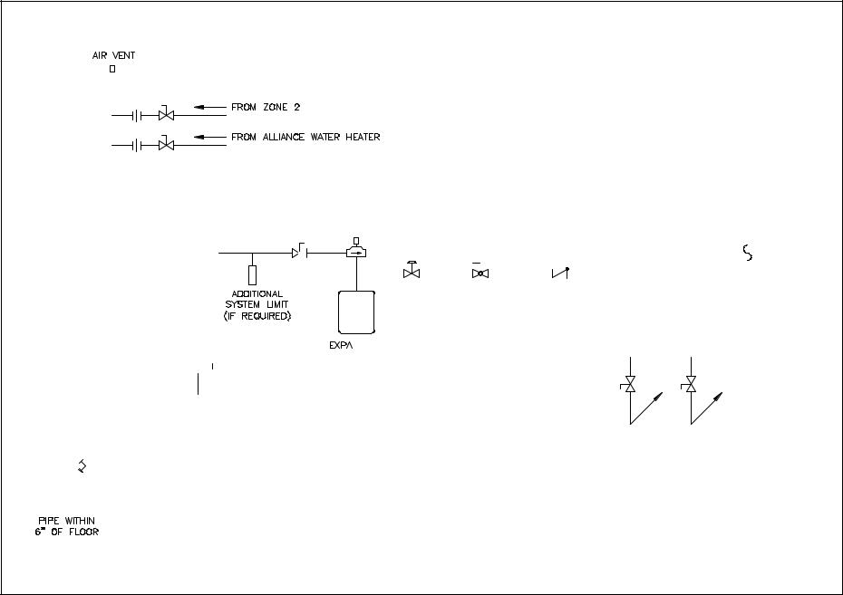
Figure 9: Boiler Piping for Zone Valve Zoned Heating Systems
 Loading...