


MULTIPLE - MODULAR
MANUAL
FOR GAS - FIRED BOILER
SERIES 8H / 8HE SIZES 5 THRU 10
 This manual must only be used by a qualified heating installer/service technician. BEFORE installing, read all instructions in this manual and all other information shipped with the boiler. Post all instructions and manuals near the boiler for reference by service personnel. Perform steps in the order given. Failure to comply could result in severe personal injury, death or substantial property damage.
|
Commercial Boilers |
|
www.burnhamcommercial.com |
81416022R1 - 3/15 |
Price - $5.00 1 |
IMPORTANT INFORMATION -
READ and save these instructions for reference
Hazard definitions
The following defined terms are used throughout this manual to bring attention to the presence of hazards of various risk levels or to important information concerning the life of the product.
Indicates an imminently hazardous situation which, if not avoided, will result in death, serious injury or substantial property damage.
Indicates a potentially hazardous situation which, if not avoided, could result in death, serious injury or substantial property damage.
Indicates a potentially hazardous situation which, if not avoided, may result in moderate or minor injury or property damage.
Indicates special instructions on installation, operation, or maintenance which are important but not related to personal injury hazards.
This boiler has a limited warranty, a copy of which is printed on the back of this manual.
It is the responsibility of the installing contractor to see that all controls are correctly installed and are operating properly when the installation is complete. The warranty for this boiler is valid only if the boiler has been installed, maintained and operated in accordance with these instructions.
DO NOT store or use gasoline or other flammable vapors or liquids in the vicinity of this or any other appliance.
If you smell gas or fuel oil vapors, do not try to operate the burner/boiler system. Do not touch any electrical switch or use any phone in the building. Immediately call the gas or oil supplier from a remotely located phone.
Burner/boiler systems produce steam or hot water in a pressurized vessel by mixing extremely flammable gaseous, liquid or solid fuels with air to produce combustion and very hot products of combustion.
Explosions, fires severe personal injury, death and/or property damage will result from improper, careless or inadequate installation, operation or maintenance of fuel-burning and boiler equipment.
2

Improper installation, adjustment, alteration, service or maintenance can cause property damage, personal injury or loss of life. Failure to follow all instructions in the proper order can cause personal injury or death. Read and understand all instructions, including all those contained in component manufacturers manuals which are provided with the appliance before installing, starting-up, operating, maintaining or servicing this appliance. Keep this manual and literature in legible condition and posted near appliance for reference by owner and service technician.
Theseboilersrequireregularmaintenanceandservicetooperatesafely. Followtheinstructionscontained in the Series 8H/8HE Installation, Operating and Service Instructions.
Installation,maintenance,andservicemustbeperformedonlybyanexperienced,skilledandknowledgeable installer or service agency.
All heating systems should be designed by competent contractors and only persons knowledgeable in the layout and installation of hydronic heating systems should attempt installation of any boiler.
It is the responsibility of the installing contractor to see that all controls are correctly installed and are operating properly when the installation is completed.
Installation is not complete unless a pressure relief valve is installed into the specified tapping on the supply manifold located on top and at rear of appliance - See Section III, Paragraph 33, ‘e’ of the Series 8H/8HE Installation, Operating and Service Instructions for details.
These boilers are NOT suitable for installation on combustible flooring.
Do not tamper with or alter the boiler or controls. Retain your contractor or a competent serviceman to assure that the unit is properly adjusted and maintained.
Clean boilers at least once a year - preferably at the start of the heating season to remove soot and scale. The inside of the combustion chamber should also be cleaned and inspected at the same time.
Have Burner and Controls checked at least once a year or as may be necessitated. Do not operate unit with jumpered or absent controls or safety devices. Do not operate unit if any control, switch, component, or device has been subject to water.
3

Appliance materials of construction, products of combustion and the fuel contain alumina, silica, heavy metals, carbon monoxide, nitrogen oxides, aldehydes and/or other toxic or harmful substances which can cause death or serious injury and which are known to the state of California to cause cancer, birth defectsandotherreproductiveharm. Alwaysusepropersafetyclothing,respiratorsandequipmentwhen servicing or working nearby the appliance.
These boilers contain very hot water under high pressure. Do not unscrew any pipe fittings nor attempt to disconnect any components of this boiler without positively assuring the water is cool and has no pressure. Always wear protective clothing and equipment when installing, starting up or servicing this boiler to prevent scald injuries. Do not rely on the pressure and temperature gauges to determine the temperature and pressure of the boiler. This boiler contains components which become very hot when the boiler is operating. Do not touch any components unless they are cool.
All appliances must be properly vented and connected to an approved vent system in good condition. Do not operate boilers with the absence of an approved vent system.
These boilers need fresh air for safe operation and must be installed so there are provisions for adequate combustion and ventilation air.
The interior of the venting and air intake systems must be inspected and cleaned before the start of the heating season and should be inspected periodically throughout the heating season for any obstructions. Clean and unobstructed venting and air intake systems are necessary to allow noxious fumes that could cause injury or loss of life to vent safely and will contribute toward maintaining the boiler’s efficiency.
These boilers are supplied with controls which may cause the boiler to shut down and not re-start without service. If damage due to frozen pipes is a possibility, the heating system should not be left unattended in cold weather; or appropriate safeguards and alarms should be installed on the heating system to prevent damage if the boiler is inoperative.
This boiler is designed to burn natural and/or LP gas only. Do not use gasoline, crankcase drainings, or any oil containing gasoline. Never burn garbage or paper in this boiler. Do not convert to any solid fuel (i.e. wood, coal). All flammable debris, rags, paper, wood scraps, etc., should be kept clear of the boiler at all times. Keep the boiler area clean and free of fire hazards.
Float type low water cutoff devices require annual inspection and maintenance. Refer to instructions in
Section V, Paragraph 7 of the Series 8H/8HE Installation, Operating and Service Instructions for inspection and cleaning instructions.
All Series 8HE cast iron boilers are designed, built, marked and tested in accordance with the ASME Boiler and Pressure Vessel Code, Section IV, Heating Boilers. An ASME Data Label is factory applied to each 8HE jacket, which indicates the boiler Maximum Allowable working Pressure (MAWP). Each cast iron section is permanently marked with the MAWP listed on the boiler’s ASME Data Label. The MAWP for all Series 8HE Boiler is 50 psi (Water Only).
It is common and acceptable practice to install these boilers in lower pressure systems, below the boiler MAWP. Therefore, in addition to Safety Relief Valves set for 50 psi, Burnham also offers Safety Relief Valves set for 30 psi (By Special Order Only).
4

Important Product safety Information
Refractory ceramic fiber Product
The Repair Parts list designates parts that contain refractory ceramic fibers
(RCF). RCF has been classified as a possible human carcinogen. When exposed to temperatures above 1805°F, such as during direct flame contact, RCF changes into crystalline silica, a known carcinogen. When disturbed as a result of servicing or repair, these substances become airborne and, if inhaled, may be hazardous to your health.
AVOID Breathing Fiber Particulates and Dust
Precautionary Measures:
Do not remove or replace RCF parts or attempt any service or repair work involving RCF without wearing the following protective gear:
1.A National Institute for Occupational Safety and Health (NIOSH) approved respirator
2.Long sleeved, loose fitting clothing
3.Gloves
4.Eye Protection
•Take steps to assure adequate ventilation.
•Wash all exposed body areas gently with soap and water after contact.
•Wash work clothes separately from other laundry and rinse washing machine after use to avoid contaminating other clothes.
•Discard used RCF components by sealing in an airtight plastic bag. RCF and crystalline silica are not classified as hazardous wastes in the United States and Canada.
first Aid Procedures:
•If contact with eyes: Flush with water for at least 15 minutes. Seek immediate medical attention if irritation persists.
•If contact with skin: Wash affected area gently with soap and water. Seek immediate medical attention if irritation persists.
•If breathing difficulty develops: Leave the area and move to a location with clean fresh air. Seek immediate medical attention if breathing difficulties persist.
•Ingestion: Do not induce vomiting. Drink plenty of water. Seek immediate medical attention.
5
|
LIST OF FIGURES |
|
|
|
PAGE |
SECTION 1.0 |
COMBUSTION, VENTILATION, VENT SYSTEMS.............................. |
8 |
Fig. 1 — 1 |
Complete Combustion of Natural Gas....................................... |
10 |
— 2 |
Confined Space, Ventilation From Inside Building..................... |
11 |
— 3 |
Confined Space, Ventilation From Outdoors.............................. |
11 |
— 4 |
Unconfined Space, Ventilation From Outdoors.......................... |
12 |
— 5 |
Constant Diameter Manifold Vent.............................................. |
13 |
— 6 |
Graduated Diameter Manifold Vent............................................ |
14 |
— 7 |
Individual Vents.......................................................................... |
15 |
SECTION 2.0 |
VENT DESIGN............................................................................... |
16 |
Fig. 2 — 1 |
Input vs. Gross Output vs. Net Rating........................................ |
18 |
— 2 |
Recommended Number of Modules.......................................... |
19 |
— 3 |
Input and Dimensional Data....................................................... |
20 |
— 4 |
Tapered Manifold Vent............................................................... |
21 |
— 5 |
Constant Diameter Manifold Vent.............................................. |
21 |
— 6 |
Dual Takeoff Constant Diameter Manifold Vent.......................... |
22 |
— 7 |
Dual Takeoff Tapered Manifold Vent........................................... |
22 |
— 8, 9 |
Constant Diameter Vent, Back-to-Back...................................... |
23 |
— 10 |
Minimum Installation Clearances............................................... |
24 |
— 11 |
Free Area of Ventilation Openings............................................. |
24 |
— 12 |
Individual Vent Table.................................................................. |
25 |
— 13 |
Common Vent Table.......................................................... |
23 & 27 |
— 14 |
Vent Connector Table................................................................. |
28 |
— 15 |
Vent Diameter vs. Chimney Area............................................... |
29 |
— 16 |
Area of Masonry Flue Tiles........................................................ |
30 |
SECTION 3.0 |
WATER PIPING............................................................................. |
31 |
Fig. 3 — 1 |
Water Piping for Parallel Pumping............................................. |
39 |
— 2 |
Water Piping for Primary-Secondary Pumping........................... |
40 |
— 3 |
Recommended Manifold Piping................................................. |
41 |
— 4 |
Module Water Flow Data............................................................ |
42 |
— 5 |
Friction vs. Water Flow — Iron Pipe........................................... |
43 |
— 6 |
Friction vs. Water Flow — Copper Pipe..................................... |
44 |
— 7 |
Equivalent Length of Pipe for 90° Elbows.................................. |
44 |
— 8 |
Volume of Water in Pipe............................................................. |
45 |
— 9 |
Compression Tank Selection Table............................................ |
45 |
— 10 |
Correction Factor for Compression Tank Selection.................... |
46 |
6

|
LIST OF FIGURES (continued) |
|
|
|
|
|
PAGE |
SECTION 3.0 |
WATER PIPING (continued) |
|
|
Fig. 3 — 11 |
Net Expansion Factors for Water............................................... |
|
46 |
— 12 |
Acceptance Factors for Diaphragm Type Tanks......................... |
|
47 |
— 13 |
Module Data-Water Side............................................................ |
|
47 |
— 14 |
Water Piping for Service Water Heater...................................... |
|
48 |
— 15 |
Service Hot Water Demand, Fixture Units................................. |
|
49 |
— 16 |
Service Hot Water Flow Rate..................................................... |
|
49 |
— 17 |
Sizing Factors for Combination Heating/Service Water............. |
|
50 |
SECTION 4.0 |
GAS PIPING.................................................................................. |
|
51 |
Fig. 4 — 1, 2 |
Recommended Gas Supply Piping................................... |
54 & 55 |
|
— 3 |
Gas Pipe Sizing Table................................................................ |
|
56 |
— 4 |
Equivalent Length of Fitting & Valves — Gas Pipe.................... |
|
56 |
— 5 |
Maximum Capacity of Pipe........................................................ |
|
57 |
— 6 |
Correction Factors for Specific Gravity...................................... |
|
57 |
— 7 |
Support of Piping........................................................................ |
|
58 |
— 8 |
Moisture and Dirt Trap................................................................ |
|
58 |
SECTION 5.0 |
CONTROLS................................................................................... |
|
59 |
Fig. 5 — 1 |
Tekmar 261, Two-Stage, EI, for Parallel Piping.......................... |
|
61 |
— 2 |
Tekmar 261, Two-Stage, EI, for Primary Secondary Piping |
.......62 |
|
— 3 |
Tekmar 263, Two-Stage, EI, for Parallel Piping.......................... |
|
63 |
— 4 |
Tekmar 263, Two-Stage, EI, for Primary Secondary Piping....... |
64 |
|
— 5 |
Tekmar 274, Two-Stage, EI, for Parallel Piping.......................... |
|
65 |
— 6 |
Tekmar 274, Two-Stage, EI, for Primary Secondary Piping....... |
66 |
|
— 7 |
Tekmar 268, Two-Stage, EI, for Parallel Piping.......................... |
|
67 |
— 8 |
Tekmar 268, Two-Stage, EI, for Primary Secondary Piping....... |
68 |
|
SECTION 6.0 |
START-UP AND SERVICE............................................................ |
|
69 |
Series 8H/8HE Boilers are NOT suitable for direct installation on combustible flooring.
Refer to the 8H/8HE Installation, Operating and Service Instructions (Part Number 81416021) for Installation
Instructions for Floor Shields that are available and required for combustible floor installations.
7

SECTION 1.0 COMBUSTION, VENTILATION & VENT SYSTEMS
1.1INTRODUCTION–Thebasicprinciplesofcombustion or burning of a gaseous fuel should be reviewed briefly in order for the reader to appreciate the necessity of:
(1)providing adequate ventilation for replacement of air consumed during the combustion process and the replacement of air carried out with the products of combustion, and (2) providing a properly designed vent system that will effectively convey the gases produced during the burning process to the outside atmosphere along with any air diluting the flue gases.
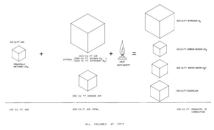
1.2COMBUSTION – In order for combustion or burning to take place three things are needed:
1)Fuel-in this case, natural gas or propane.
2)Oxygen-oxygen is obtained from the air which is approximately 20% oxygen and approximately 80% nitrogen. Nitrogen is inert and will not burn.
3)Heat-gas will not urn until its temperature is raised to its ignition point, approximately 1100-1200°F. A gas burning pilot (open flame) or electrical means (spark) is used for the initial ignition after which the flame itself provides the heat needed to sustain combustion.
If any of the three are taken away, combustion cannot take place.
Becausethemixingofairandfuelisnot100%complete, more air than is actually needed called excess air must be supplied to the appliance in order for burning to be complete. This is shown in Figure 1-1.
If the supply of fresh air is inadequate or is not continuallyreplenishedasitisusedup,carbonmonoxide(CO) andHydrogen(H2)aswellastheproductsofcombustion shown in Fig. 1-1 may be produced. This is undesirable since carbon monoxide is toxic and some-times lethal even in small quantities.
In addition to the fresh air required for combustion, fresh air is also required to dilute the flue products so thattheresultantfluegastemperatureisreducedtowhat is considered a safe level. Thus, a total of 16 cu. Ft. of air may be required for each cu. ft. of gas burned, 12.5 cu. ft. for the combustion process and 3.5 cu. ft. for the dilution process.
1.3VENTILATION–Freshairrequirementsfortheheating plantwillvarywiththespaceinwhichtheplantislocated as described and illustrated in succeeding paragraphs. Reference to free area of air inlets is made in the text sincelouvers,grilles,orscreensaresometimesusedator in the inlet and these have a blocking effect. This must be taken into consideration in order to obtain proper quantities of fresh air. If the free areas of these devices arenotknown,itmaybeassumedthatwoodlouverswill have20-25%freeareaandmetallouversandgrilleswill have 60-75% free area.
For installation in boiler rooms with ventilation air provided from inside of building having adequate infiltrationfromoutdoors,eachopeningshallhaveafree area of not less than one (1) square inch per 1000 Btuh of the total input rating of the heating plant and other fuel burning appliance in the boiler room. See Figure 1-2.
For installation in boiler rooms with ventilation air provideddirectlyfromoutdoors,eachopeningshallhave a free area of not less than one (1) square inch per 4000 Btuhofthetotalinputratingoftheheatingunitandother fuelburningapplianceintheboilerroom. Eachopening should be equipped with a screen covering whose mesh should not be less than ¼ inch and each opening should beconstructedsothattheycannotbeclosed. SeeFigure 1-3.
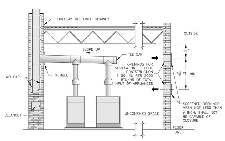
Normally,iftheboilerisinstalledinanunconfinedspace, anadequateamountofventilationairwillbesuppliedby natural infiltration. If however, the unconfined space is ofunusuallytightconstruction,airfromoutdoorswillbe needed. A permanent opening or openings with a total free area of not less than one (1) square inch per 5000 Btuh of the total input rating of the heating plant and other fuel burning appliances in the unconfined space is necessary. If ducts (minimum rectangular area of 3 square inches) are used, they must be the same crosssectional area as the free area of the opening to which they connect. Screening to cover the openings to the outside should not be smaller than ¼ inch mesh and each opening should be constructed so that they cannot be closed. See Figure 1-4.
Adequate combustion and ventilation air must be provided to assure proper combustion.
Theimportanceofadequateandproperventilation cannot be overemphasized. It must also be understoodthatventingandventilationmustalways be considered together. They are both part of the same system and must balance each other.
If exhaust fans are utilized such as for make-up air, the make-up air should not be drawn from the same space that is the source of combustion air for the heating plant unless adequate provisions are made to supply additional outside air so that the space surrounding the heating unit is not under a negative pressures (less than outdoor pressure).
Blowers should not be used to forcibly provide ventilation unless controlled to a point where static pressure in the space in which the heating plant is located is equal to the outdoor pressure.
8

(continued)
Excess pressure resulting from larger than necessary volumes of fresh air will cause excessive dilution of the flue products resulting in low flue gas temperatures. If lowered below the dew point, condensation of the moisture in the flue gases will occur and, if continued over an extended period of time, will corrode vents, drafthoods, heat exchangers, and burners.
There are certain elements known as halogens
(fluorine, chlorine, bromide, iodine and astatine) which are utilized in many commercial products (refrigerants, solvents, spray can propellant, etc.). If these products must be used near the heating plant, extra precaution must be taken to obtain uncontaminated air from the outside, otherwise severe corrosion will occur in the boiler and vent system.
When an existing boiler is removed from a common venting system, the common venting system is likely to be too large for proper venting of the appliances remaining connected to it.
1.4VENTING – As pointed out before, venting is the process of removing of the flue products. There are basically two types of venting: atmospheric (or gravity) and power venting. Further discussion will be limited to atmospheric vent systems since it is, by far, the most commonly used and the most
applicable to the Series 8H/8HE modular boilers. The atmospheric system is composed of numerous parts and it is necessary to understand the function and operation of each part in order to properly design the system.
Do not alter boiler draft hood or place any obstruction or non-approved damper in the breeching or vent system. Flue gas spillage can occur. Unsafe boiler operation will occur.
1.4.1DRAFTHOOD – The flue outlet of a heating appliance such as the Series 8H/8HE module cannot be connected directly to the vent system for the following reasons:
a)The amount of air drawn thru the combustion chamber would vary with the height of the vent pipe. Hence, there would be little or no chance of maintaining the same air flow rate thru the appliance for the variety of installation conditions which invariably are encountered.
b)There would be no way to compensate for variable wind conditions encountered at the terminal of the vent. If wind conditions created a negative
pressure at the vent terminal, this negative pressure would tend to increase the flow thru the vent system – this phenomena is referred to as updraft. If the wind created a positive pressure at the terminal, the flow through the vent system would be retarded or reversed – this condition is referred to as downdraft.
c)There would be no avenue of escape for the flue gases in case the vent became blocked.
d)Flue gases, if undiluted, could reach temperatures which would create a potential fire hazard if the flue gases were to strike flammable surfaces.
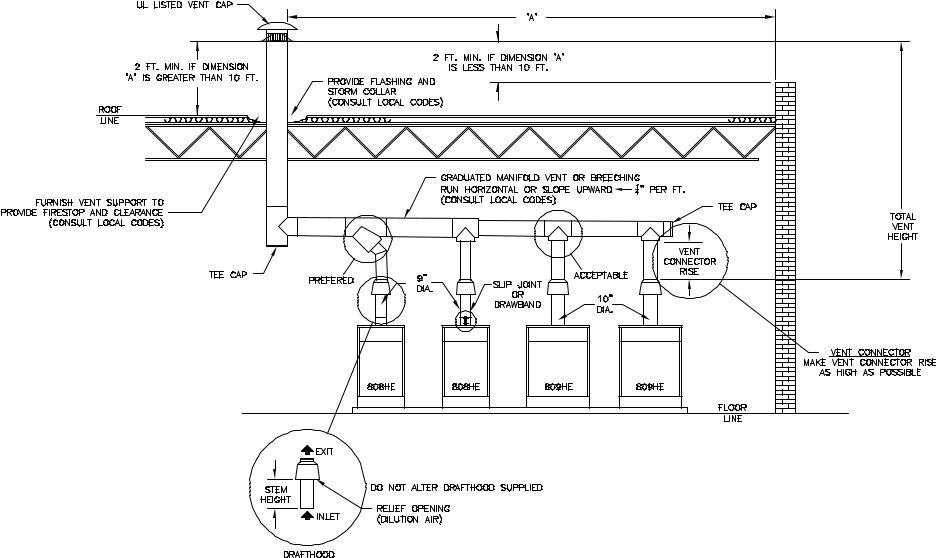
To overcome all of the deficiencies outlined above, an AGA listed vertical to vertical type of drafthood is furnished with each Series 8H/8HE boiler, see insert of Fig. 1-5. The inlet opening of the drafthood is connected to the flue outlet of the boiler, and the exit or outlet opening of the drafthood is connected to the riser portion of the vent connector. The inlet and exit diameter and the stem height of the drafthood are a function of boiler size since they were determined only after extensive testing and after certification by the American Gas Association and by the Canadian Gas Association. Therefore, THE DRAFTHOOD MUST NOT BE ALTERED IN ANY MANNER.
1.4.2VENT CONNECTOR – see Fig. 1-5. The vent connector is that portion of the vent system which connects the exit (outlet) of a drafthood of an individual appliance to the manifold vent (breeching) servicing two or more boilers. If there is a horizontal run in the vent connector, this horizontal run is known as a lateral. Since the vent connector may enter the bottom or the side of the manifold vent, the vent connector rise is the vertical distance from the drafthood outlet to the lowest level at which
the connector enters the manifold. A slip joint or drawband, as illustrated in Fig. 1-5, will facilitate installation of connectors as well as replacement of parts in that portion of the system should it ever become necessary.
1.4.3MANIFOLD AND COMMON VENTS – see Figs.
1-5, 1-6. A manifold vent or breeching is a horizontal extension of the vertical common vent. The common vent, which is sized to handle the total load when
all modules are operating, can be of masonry construction, single-wall metal pipe, or type B Gas Vent Pipe – consult local codes. A UL Listed vent cap should be installed, if possible, at the exit of the common vent to assure full vent capacity and freedom from adverse wind effects.
Total vent height is the vertical distance between the exit of the common vent and the exit or outlet of the drafthood. Regardless of the calculated total vent height required for capacity, all vents must be correctly terminated a sufficient distance above the roof surface and away from nearby obstructions, see Figs. 1-5 and 1.6. This is to avoid adverse
9
wind effects or pressure areas which may reduce or impede vent flow. This does not imply that terminations at these locations will assure proper venting in every instance. Because winds fluctuate in velocity, direction, and turbulence, and because these same winds impose varying pressures on the entire structure, no simple method of analysis or
reduction to practice exists for this complex situation. Manifold vents may be run horizontally or sloped upwards toward the common vent. Slope should not exceed ¼” per foot unless required otherwise by local codes. Regardless, minimum vent connector rise as determined for each appliance must be maintained.
Manifold vents may be of constant diameter (Fig. 1-5) in which case they are of the same size as the common vent or its equivalent. Manifolds may also be tapered (Fig. 1-6) for the actual input to a particular section of the manifold. Difference in operating characteristics between properly sized constant diameter manifold vents or tapered manifold vents are negligible and choice is usually dictated by convenience and cost.
1.4.4INDIVIDUAL VENTS – Economics thru the use of smaller vent pipe and the elimination of fittings could dictate the use of an individual vent system for each module (see Fig. 1-7) rather than a combined vent system. If the individual vents are of the proper diameter and the total vent height is a minimum of 5 ft., the systems are self venting and more reliable
than a combined vent system since, in the latter, it is impossible to anticipate all contingencies.
1.4.5VENTAND CHIMNEY MATERIALS AND CONSTRUCTION – The materials of construction for vents and chimneys include single-wall metal, various multi-wall air and mass insulated types as well as masonry, which could be precast or site constructed. In many instances, national or local codes will govern what type may be used. Where choice is possible, many advantages can be listed for the UL Listed double wall metal type B vent:
1)warm up is faster with type B vents than vents having greater mass
2)type B vents permit closer clearance to combustible material than single wall metal vents unless special precautions are taken with the latter
3)type B vents are less prone to condensation and corrosion than single wall metal vents
4)type B vents are lightweight, easy to handle and assemble
Manufacturer’s instructions relative to installation of their product should be followed as long as they comply with the National Fuel Gas Code and/or local codes. Some items to consider are:
1)support of lateral runs so that vent pipe does not sag
COMPLETE COMBUSTION OF NATURAL GAS
FIGURE 1-1
10
CONFINED SPACE, VENTILATION AIR PROVIDED
FROM INSIDE OF BUILDING
FIGURE 1-2
CONFINED SPACE, VENTILATION AIR PROVIDED
FROM OUTDOORS
FIGURE 1-3
11
2)support of common vent where it passes thru a ceiling or roof
3)clearances to combustible material – use of thimbles
4)firestops
5)flashing and storm collars
6)guying or bracing of common vent pipe above roof
7)securing and gas tightness of joints
8)lightning arrester if top of metal vent is one of the highest points on the roof
9)proper termination of vent connection at masonry chimney – vent should enter chimney at a point above the extreme bottom of chimney – vent should be flush with inside of chimney and sealed (see Fig. 1-5)
10)never connect a gas vent to a chimney serving a fireplace unless the fireplace has been permanently sealed
11)never pass any portion of a vent system thru a circulating air duct or plenum.
UNCONFINED SPACE—TIGHT CONSTRUCTION VENTILATION AIR PROVIDED FROM OUTDOORS
FIGURE 1-4
12

13
CONSTANT DIAMETER MANIFOLD VENT OR BREECHING
TWO THROUGH EIGHT MODULES
FIGURE 1-5
14
GRADUATED DIAMETER MANIFOLD VENT OR BREECHING
TWO THROUGH EIGHT MODULES
FIGURE 1-6

15
INDIVIDUAL VENTS
TWO THROUGH EIGHT MODULES
FIGURE 1-7

SECTION 2.0 VENTS
Inspect existing chimney before installing boilers. Failure to clean or replace perforated pipe or tile lining will cause severe injury or death.
2.1Vents, or breeching ducts, are generally less flexible in design location than are water pipes, gas pipes or electrical lines. To avoid conflicts for a given location, design and layout the vents in this section before proceeding to other sections of this manual.
2.2Obtain a scaled drawing of the boiler room. Note the floor size, ceiling height, exterior walls, and chimney location, if provided.
2.3Determine the input required to the system. It is recommended that the heating load be determined by an accurate calculation of the heat loss of the structure using methods contained in the ASHRAE Guide. If service water is to be added capacity as described in paragraph 3.13 of this manual. The boiler capacity so obtained is net rating to input. Record the input required on the boiler room drawing.
2.4Using Figure 2-2 for the input found in 2.3 above, find the number of modules recommended. Those module combinations shown represent the best selection for lowest first cost. Other combinations may be selected, within the following guidelines:
1)Modules using a sequencing control system, such as Tekmar described in Section 5.0, should not vary by more than one size.
2)Modules using a combined vent system should not vary by more than one size.
3)The combined vent sizing procedures in this section are based on a maximum of eight modules using a common vent system. If it is desired to serve more than eight modules with a common vent system, the specific requirements should
be referred to the BURNHAM COMMERCIAL Application Engineering Department.
Refer to Figure 2-3 for individual module inputs.
2.4.1Sketch on the boiler room drawing the approximate location of the modules. Figures 2-4 thru 2-9 show several layouts that can be used depending on the size and shape of the boiler room and chimney location, if provided. Refer to Figure 2-3 for dimensional data on individual modules. Select the layout which best fits the boiler room. Bear in mind that for combined vent systems it is desirable to keep horizontal laterals as short as possible. On a combined vent system for which a fixed chimney is provided, it is desirable to place the first module close to the chimney.
2.4.2If the factory fabricated water manifolds are to be used, 805H, 806H, and 807HE modules should be laid out with 28½” module spacing and 808HE, 809HE,
and 810HE modules should be laid out with 40” module spacing. If an 807HE and an 808HE module are to be connected to a common manifold, use the longer manifold with 40” spacing. Otherwise, any module spacing that allows at least 1 inch jacket –to- jacket spacing if acceptable, pending local or state code requirements that may require greater module to module spacing.
2.4.3Refer to Figure 2-10 for minimum clearances around modules to combustible materials and for service access. CAUTION: Local fire ordinances may be more restrictive and should be complied with.
2.5One of the serious errors made in layout of a boiler room is the failure to provide sufficient ventilation air. Insufficient ventilation air will cause incomplete combustion, poor ignition, accumulation of soot in the boiler, or the production of toxic gases. Many service calls for dirty boilers, nuisance lock outs, noisy ignition, or obnoxious odors are traceable to insufficient ventilation air. Use Figure 2-11 at the input desired to find the recommended free area of the ventilation opening required. Reference to Figures 1-2 thru 1-4 should be made in order to understand the types of installations described in the headings of Figure 2-11. Record the free ventilation area required on the plans of the boiler room and sketch the openings like those shown in figures 1-2 thru 1-4 respectively.
2.6Individual vents as shown in Figure 1-7 are highly recommended if the job site conditions allow. Individual vents are particularly useful in boiler rooms having a low ceiling height. Individual vents are easy to design and in many cases result in the lowest installed cost. They also are the most dependable in operation and less susceptible to condensation than are combined vents. To size individual vents, use Figure 2-12 with the vent height available, the lateral length, size of module and type of vent pipe.
2.7Combined vents will perform satisfactorily if strict design procedures are followed. Referring to Figures 2-4 thru 2-9, note that a connector rise F of at least one foot is required. A connector rise F of three feet is desirable. Thus, to make the desired connector rise and have space for the manifold vent, the minimum boiler room ceiling height must be equal to:
32½” Module Height
+) Drafthood Height
+F Minimum Connector Rise
+ CV Manifold Diameter
+ 6” Clearance
=Minimum Ceiling Height
If the minimum ceiling height above is not available, common vents will not perform satisfactorily and should not be used.
16

2.7.1If the minimum ceiling height is available, proceed to size the common vent CV in Figure 2-13. Enter the left hand column at the desired total input and move right to the column corresponding to your H, least total vent height, and read the diameter of the common vent. If more than one elbow is used, increase CV by one pipe size for each elbow more
than one. Proceed to size the connector rise diameter CN by entering Figure 2-14 at H available and move right to the column headed F. On the line for available connector rise move right to the CN columns headed by the module sizes selected in 2.4 above. Read the connector diameter(s). Record these sizes on the plans of the boiler room.
2.7.2If a tapered or graduated manifold vent is desired, use the same procedures above for sizing the intermediate manifold diameter but for the total input of the modules served by intermediate tapered or graduated manifold vent.
2.7.3Within Figure 2-12 are several entries of NR. This means that the combination involved is not recommended. The most common reason for a combination to be designated NR is that
condensation inside the vent pipe is likely to occur. This is particularly true of single wall vent pipe. Combinations outside the shaded area in Figure 2-13 are also not recommended for single wall vent pipe. Additionally, single wall vent pipe should not be used with five or more modules because the dilution from the unfired modules plus the lower surface temperature of single wall pipe makes condensation and the resulting corrosion very likely.
2.8If a masonry chimney is desired, the minimum cross sectional area of the chimney is found in Figure 2-15 as a function of the vent diameter. Figure 2-16 shows the area of standard chimney tiles by size.
2.9The following is an example of the recommended design procedures.
Example: A 3 story apartment house needs a total boiler capacity including service water hating, of 1,849,500 Btu/Hr net rating. The boiler room is in a one story added portion of the building, of non-
combustible construction, similar to Figures 1-6 or 1-7 and is 20 feet long, 10 feet wide with a clear ceiling of 12 feet. No chimney is provided. Select and size the vent system.
1)Refer to Figure 2-1 to convert net rating to input. Input = 1,849,500 x 1.44 = 2,663,280 Btuh = 2,663 MBH.
2)From Figure 2-2 find the closest recommended module combination having an input of 2663 MBH. It is found that an input of 2710 MBH is the closest size and is composed of five 809HE and one 808HE modules.
3)Sketch approximate module locations on the boiler room plans using minimum clearances recommended in 2.4 above. In this case there is space to
lay-out the five modules in line along one wall on 40” centers with ample service clearances, front, rear, and sides, per Figure 2-10.
4)Determine the ventilation areas required from figure 2-11. It is a confined space but outdoor air is readily available through vents in the exterior wall. Use the equation for Confined with Outdoor Vent:
MBH Input = 2,710. = 677.5 sq. in. 4.0
of free ventilation area required.
5)Select the type of vent system – individual or combined.
For an individual vent system use Figure 2-12 to determine the vent size(s). In this example, the height of drafthoods above the floor = 32½” + 33½” = 66” = 5½ feet. The least total vent height is calculated from the drafthood up to the top of the vent pipe which must be at least two feet above the roof.
12 Ft. Ceiling Height
- 5½ Ft. Drafthood Height
+2 Ft. Ceiling Thickness
+2 Ft. Vent Extension
=10½ Ft. total Vent Height, H
Enter Figure 2-12 at H = 10 Ft. and move right to L = O Ft. Move right to 809HE column and find 8” diameter for type B pipe and 10” for single wall pipe. Continue to the right on the same line to 809HE column and find 9” diameter for type B pipe and 10” for single wall pipe. Mark these sizes on the drawing of the boiler room. If no more than two 90° elbows are used in the system, no corrections are necessary. The design is complete.
6)If a combined vent is desired such as in Figure 1-5, use Figure 2-13 to find the common vent size, CV. Enter Figure 2-13 at 2710. MBH input. Move right to the column H = 10 Ft. and find common vent diameter CV = 26” for type B pipe and single wall is not recommended. Enter Figure 2-14 at H = 10 Ft. and move right to F = 3 Ft. Move right and find connector diameter CN of 12” in the 809HE column and 12” in the 810HE column. Calculate minimum ceiling height.
32½” Module Height
+33½” Drafthood Height, D
+36” Desired connector Rise, F
+26” Manifold Diameter, CV
+ 6” Clearance
=11’2” Minimum Ceiling Height
A twelve foot clear ceiling height will work. With only one elbow, no correction is necessary. The design of a constant diameter manifold vent is complete. Mark these vent and connector sizes on the drawing of the boiler room.
17

7)If a tapered or graduated manifold vent is desired, such as in Figure 1-6 the horizontal and vertical portion of the vent serving five modules is also complete with 6) above. However, to size the manifold vent at an intermediate position such as CV3 in Figure 2-4, use Figure 2-13 for the MBH Input of the modules served by that position of the manifold vent. The Input MBH of each module can be determined from Figure 2-3. In this case CV3 serves two modules having an input of
920 MBH. Enter figure 2-13 at an input of 920 MBH. Move right to H = 10 Ft. and find CV3 = 14” diameter. Mark this vent diameter size on the drawing of the boiler room. Thus a graduated manifold vent design is complete. It is possible with this procedure to reduce the manifold vent
size after each module. However, from a practical standpoint, the cost of fittings may offset the lower cost of smaller vent pipe.
2.10All of the above procedure is based on data found in the ASHRAE Guide, 1975 Equipment Volume, Chapter 26. The basic chimney equation is expressed as follows:
(di)² (∆PB) 0.5
I = 4.13 x 10⁵ x M |
x (KTm) |
where: I = Operating heat input, BTUH
di = Inside diameter of the common vent or manifold vent
M = Mass flow input ratio, lb. of products per 1000 BTU of fuel burned. A value of 1.60 was used based on 5.3% CO2 after dilution. An additional 15% dilution was added for each unfired module.
∆P = Pressure difference or loss in the system acting to cause flow, inches of water. Use
0.537 inches water per 100 Ft. of pipe.
B = Sea level barometer used —29.92” Hg
K = Resistance loss coefficients, dimensionless. Tm = Temperature in vent system at average
conditions, °Fabs.
The serious Engineer should become familiar with the above basic equation and the range of the variables that may be encountered. The tables in Figures 2-12 thru 2-14 should not be extrapolated. If system conditions do not fall within the limit of the tables, vent sizes must be calculated using the chimney equation above as described in the ASHRAE Guide.
RELATIONSHIP OF INPUT, GROSS OUTPUT, AND NET RATING FOR SERIES 8H/8HE MODULES
FIGURE 2-1
18
Total |
Recommended Number of Modules |
||||||
Input |
|
|
|
|
|
|
|
805H |
806H |
807HE |
808HE |
809HE |
810HE |
||
MBH |
|||||||
|
|
|
|
|
|
|
|
504 |
2 |
|
|
|
|
|
|
567 |
1 |
1 |
|
|
|
|
|
|
|
|
|
|
|
|
|
630 |
|
2 |
|
|
|
|
|
655 |
|
1 |
1 |
|
|
|
|
680 |
|
|
2 |
|
|
|
|
|
|
|
|
|
|
|
|
750 |
|
|
1 |
1 |
|
|
|
820 |
|
|
|
2 |
|
|
|
870 |
|
|
|
1 |
1 |
|
|
|
|
|
|
|
|
|
|
920 |
|
|
|
|
2 |
|
|
965 |
|
|
|
|
1 |
1 |
|
1010 |
|
|
|
|
|
2 |
|
|
|
|
|
|
|
|
|
1090 |
|
|
2 |
1 |
|
|
|
1160 |
|
|
1 |
2 |
|
|
|
1230 |
|
|
|
3 |
|
|
|
|
|
|
|
|
|
|
|
1280 |
|
|
|
2 |
1 |
|
|
1330 |
|
|
|
1 |
2 |
|
|
1380 |
|
|
|
|
3 |
|
|
|
|
|
|
|
|
|
|
1425 |
|
|
|
|
2 |
1 |
|
1470 |
|
|
|
|
1 |
2 |
|
1515 |
|
|
|
|
|
3 |
|
|
|
|
|
|
|
|
|
1570 |
|
|
1 |
3 |
|
|
|
|
|
|
|
|
|
|
|
1640 |
|
|
|
3 |
1 |
|
|
1690 |
|
|
|
3 |
1 |
|
|
1740 |
|
|
|
2 |
2 |
|
|
|
|
|
|
|
|
|
|
1790 |
|
|
|
1 |
3 |
|
|
1840 |
|
|
|
|
4 |
|
|
1885 |
|
|
|
|
3 |
1 |
|
|
|
|
|
|
|
|
|
1930 |
|
|
|
|
2 |
2 |
|
1975 |
|
|
|
|
1 |
3 |
|
2020 |
|
|
|
|
|
4 |
|
|
|
|
|
|
|
|
|
2100 |
|
|
|
4 |
1 |
|
|
2150 |
|
|
|
3 |
2 |
|
|
2200 |
|
|
|
2 |
3 |
|
|
2250 |
|
|
|
1 |
4 |
|
|
|
|
|
|
|
|
|
|
Total Input |
Recommended Number of Modules |
||
|
|
|
|
MBH |
808HE |
809HE |
810HE |
|
|||
|
|
|
|
2300 |
|
5 |
|
2345 |
|
4 |
1 |
2390 |
|
3 |
2 |
|
|
|
|
2435 |
|
2 |
3 |
2480 |
|
1 |
4 |
2525 |
|
|
5 |
|
|
|
|
2610 |
3 |
3 |
|
2660 |
2 |
4 |
|
2710 |
1 |
5 |
|
2760 |
|
6 |
|
|
|
|
|
2805 |
|
5 |
1 |
2850 |
|
4 |
2 |
2895 |
|
3 |
3 |
|
|
|
|
2940 |
|
2 |
4 |
2985 |
|
1 |
5 |
3030 |
|
|
6 |
|
|
|
|
3070 |
3 |
4 |
|
|
|
|
|
3170 |
1 |
6 |
|
3220 |
|
7 |
|
3265 |
|
6 |
1 |
|
|
|
|
3310 |
|
5 |
2 |
3355 |
|
4 |
3 |
3400 |
|
3 |
4 |
|
|
|
|
3475 |
|
2 |
5 |
3490 |
|
1 |
6 |
3535 |
|
|
7 |
|
|
|
|
3630 |
1 |
7 |
|
|
|
|
|
3680 |
|
8 |
|
3725 |
|
7 |
1 |
3770 |
|
6 |
2 |
|
|
|
|
3815 |
|
5 |
3 |
3860 |
|
4 |
4 |
3905 |
|
3 |
5 |
|
|
|
|
3850 |
|
2 |
6 |
3995 |
|
1 |
7 |
4040 |
|
|
8 |
|
|
|
|
FIGURE 2-2
19

Boiler |
Input |
|
Dimensions (inch) |
|
Recommended |
Water |
Approx. |
|||
|
|
|
|
|
Chimney Size |
Content |
Shipping |
|||
Model |
(MBH) |
"A' |
"B" |
"C" |
"D" |
"E" |
||||
(Round) |
(Gallons) |
Weight (LB) |
||||||||
805H |
252 |
20 |
10 |
7 |
24-13/16 |
16-1/8 |
7" dia. x 15 ft. |
11.9 |
680 |
|
|
|
|
|
|
|
|
|
|
|
|
806H |
315 |
23-3/4 |
11-7/8 |
8 |
27-13/16 |
18 |
8" dia. x 15 ft. |
13.9 |
770 |
|
|
|
|
|
|
|
|
|
|
|
|
807HE |
340 |
27-1/2 |
13-3/4 |
9 |
27-13/16 |
18 |
8" dia. x 15 ft. |
15.9 |
870 |
|
808HE |
410 |
31-1/4 |
15-5/8 |
9 |
30-13/16 |
20 |
8" dia. x 15 ft |
17.9 |
950 |
|
|
|
|
|
|
|
|
|
|
|
|
809HE |
460 |
35 |
17-1/2 |
10 |
33-1/2 |
22 |
10" dia. x 15 ft |
19.9 |
1040 |
|
|
|
|
|
|
|
|
|
|
|
|
810HE |
505 |
38-3/4 |
19-3/8 |
10 |
33-1/2 |
22 |
10" dia. x 15 ft |
21.9 |
1140 |
|
|
|
|
|
|
|
|
|
|
|
|
(1)Special base required for installations on combustible flooring; adds 4-3/4" to boiler height (floor to jacket top panel is 37-1/4").
(2)Gas connection size: 1 NPT
(3)Maximum Allowable Working Pressure: 50 psi (Water Only)
(4)Items shown in hidden lines supplied by installer.
FIGURE 2-3
20
FIGURE 2-4
FIGURE 2-5
21

FIGURE 2-6
FIGURE 2-7
22
 Loading...