


INSTALLATION, OPERATING AND SERVICE INSTRUCTIONS FOR
SERIES 5B
GAS-FIRED BOILER
3050579
 This manual must only be used by a qualified heating installer/service technician. BEFORE installing, read all instructions in this manual and all other information shipped with the boiler. Post all instructions and manuals near the boiler for reference by service personnel. Perform steps in the order given. Failure to comply could result in severe personal injury, death or substantial property damage.
|
Commercial Boilers |
|
www.burnhamcommercial.com |
8141302R18 - 1/15 |
Price - $5.00 |
1
IMPORTANT INFORMATION -
READ and save these instructions for reference
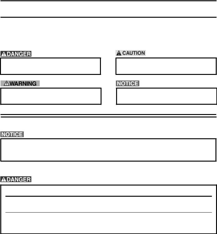
Hazard definitions
The following defined terms are used throughout this manual to bring attention to the presence of hazards of various risk levels or to important information concerning the life of the product.
Indicates an imminently hazardous situation which, if not avoided, will result in death, serious injury or substantial property damage.
Indicates a potentially hazardous situation which, if not avoided, could result in death, serious injury or substantial property damage.
Indicates a potentially hazardous situation which, if not avoided, may result in moderate or minor injury or property damage.
Indicates special instructions on installation, operation, or maintenance which are important but not related to personal injury hazards.
This boiler has a limited warranty, a copy of which is printed on the back of this manual.
It is the responsibility of the installing contractor to see that all controls are correctly installed and are operating properly when the installation is complete. The warranty for this boiler is valid only if the boiler has been installed, maintained and operated in accordance with these instructions.
DO NOT store or use gasoline or other flammable vapors or liquids in the vicinity of this or any other appliance.
If you smell gas or fuel oil vapors, do not try to operate the burner/boiler system. Do not touch any electrical switch or use any phone in the building. Immediately call the gas or oil supplier from a remotely located phone.
Burner/boilersystemsproducesteamorhotwaterinapressurizedvesselbymixingextremelyflammable gaseous, liquid or solid fuels with air to produce combustion and very hot products of combustion. Explosions,firesseverepersonalinjury,deathand/orpropertydamagewillresultfromimproper,careless or inadequate installation, operation or maintenance of fuel-burning and boiler equipment.
2

Improper installation, adjustment, alteration, service or maintenance can cause property damage, personal injury or loss of life. Failure to follow all instructions in the proper order can cause personal injury or death. Read and understand all instructions, including all those contained in component manufacturers manuals which are provided with the appliance before installing, starting-up, operating, maintaining or servicing this appliance. Keep this manual and literature in legible condition and posted near appliance for reference by owner and service technician.
This boiler requires regular maintenance and service to operate safely. Follow the instructions contained in this manual.
Installation,maintenance,andservicemustbeperformedonlybyanexperienced,skilledandknowledgeable installer or service agency.
All heating systems should be designed by competent contractors and only persons knowledgeable in the layout and installation of hydronic heating systems should attempt installation of any boiler.
It is the responsibility of the installing contractor to see that all controls are correctly installed and are operating properly when the installation is completed.
Installation is not complete unless a pressure relief valve is installed into the specified tapping on the supply manifold located on top and at rear of appliance - See Section III, Paragraph 33, ‘e’ of this manual for details.
This boiler is NOT suitable for installation on combustible flooring.
Do not tamper with or alter the boiler or controls. Retain your contractor or a competent serviceman to assure that the unit is properly adjusted and maintained.
Clean boiler at least once a year - preferably at the start of the heating season to remove soot and scale. The inside of the combustion chamber should also be cleaned and inspected at the same time.
Have Burner and Controls checked at least once a year or as may be necessitated. Do not operate unit with jumpered or absent controls or safety devices. Do not operate unit if any control, switch, component, or device has been subject to water.
3

Appliance materials of construction, products of combustion and the fuel contain alumina, silica, heavy metals, carbon monoxide, nitrogen oxides, aldehydes and/or other toxic or harmful substances which can cause death or serious injury and which are known to the state of California to cause cancer, birth defectsandotherreproductiveharm. Alwaysusepropersafetyclothing,respiratorsandequipmentwhen servicing or working nearby the appliance.
This boiler contains very hot water under high pressure. Do not unscrew any pipe fittings nor attempt to disconnect any components of this boiler without positively assuring the water is cool and has no pressure. Always wear protective clothing and equipment when installing, starting up or servicing this boiler to prevent scald injuries. Do not rely on the pressure and temperature gauges to determine the temperature and pressure of the boiler. This boiler contains components which become very hot when the boiler is operating. Do not touch any components unless they are cool.
This appliance must be properly vented and connected to an approved vent system in good condition. Do not operate boiler with the absence of an approved vent system.
This boiler needs fresh air for safe operation and must be installed so there are provisions for adequate combustion and ventilation air.
The interior of the venting and air intake systems must be inspected and cleaned before the start of the heating season and should be inspected periodically throughout the heating season for any obstructions. Clean and unobstructed venting and air intake systems are necessary to allow noxious fumes that could cause injury or loss of life to vent safely and will contribute toward maintaining the boiler’s efficiency.
This boiler is supplied with controls which may cause the boiler to shut down and not re-start without service. If damage due to frozen pipes is a possibility, the heating system should not be left unattended in cold weather; or appropriate safeguards and alarms should be installed on the heating system to prevent damage if the boiler is inoperative.
This boiler is designed to burn natural and/or LP gas only. Do not use gasoline, crankcase drainings, or any oil containing gasoline. Never burn garbage or paper in this boiler. Do not convert to any solid fuel
(i.e. wood, coal). All flammable debris, rags, paper, wood scraps, etc., should be kept clear of the boiler at all times. Keep the boiler area clean and free of fire hazards.
Float type low water cutoff devices require annual inspection and maintenance. Refer to instructions in
Section V, Paragraph 7 for inspection and cleaning instructions.
Series 5B cast iron boilers are designed, built, marked and tested in accordance with the ASME Boiler and Pressure Vessel Code, Section IV, Heating Boilers. An ASME Data Label is factory applied to each Series 5B jacket, which indicates the boiler Maximum Allowable Working Pressure (MAWP). Each cast iron section is permanently marked with the MAWP listed on the boiler’s ASME Data Label. Those values for the Series 5B are as follows:
MAWP, Water - 50 PSI
MAWP, Steam - 15 PSI
4

SECTION I – EQUIPMENT CHECK LIST
U.S.A. EQUIPMENT CHECK LIST
(For Canadian Equipment Check List, Turn to Pages 7 and 8)
This Equipment Check List has been provided so that the Installer can determine if all parts have been provided for the boiler ordered. It covers standard equipment for both steam and water boilers without Tankless Heaters. Heaters or optional equipment ordered will be in addition to, or in lieu of, equipment shown below.
By opening cartons in numerical sequence, boiler assembly is simplified. If there is an exception, it will be pointed out in the boiler assembly procedure. When it does occur, you will find that assembly of the boiler is further simplified.
BOILER SIZE
|
5006B |
5007B |
5008B |
5009B |
5010B |
5011B |
5012B |
5013B |
5014B |
5015B |
5016B |
5017B |
5018B |
5019B |
5020B |
5021B |
5022B |
5024B |
5026B |
|
|
|
|
|
|
|
|
|
|
|
|
|
|
|
|
|
|
|
|
|
|
(1) |
1 |
1 |
1 |
1 |
1 |
1 |
1 |
1 |
1 |
1 |
1 |
1 |
1 |
1 |
1 |
1 |
1 |
1 |
1 |
|
LEH |
||||||||||||||||||||
|
|
|
|
|
|
|
|
|
|
|
|
|
|
|
|
|
|
|
||
(1) |
1 |
1 |
1 |
1 |
1 |
1 |
1 |
1 |
1 |
1 |
1 |
1 |
1 |
1 |
1 |
1 |
1 |
1 |
1 |
|
REH |
||||||||||||||||||||
|
|
|
|
|
|
|
|
|
|
|
|
|
|
|
|
|
|
|
||
(1) |
4 |
5 |
6 |
7 |
8 |
8 |
9 |
10 |
11 |
12 |
13 |
14 |
15 |
16 |
16 |
17 |
18 |
19 |
21 |
|
C |
||||||||||||||||||||
|
|
|
|
|
|
|
|
|
|
|
|
|
|
|
|
|
|
|
||
(2) |
--- |
--- |
--- |
--- |
--- |
--- |
--- |
--- |
--- |
1 |
1 |
1 |
1 |
1 |
1 |
2 |
2 |
3 |
3 |
|
CX |
||||||||||||||||||||
|
|
|
|
|
|
|
|
|
|
|
|
|
|
|
|
|
|
|
||
(3) |
--- |
--- |
--- |
--- |
--- |
1 |
1 |
1 |
1 |
--- |
--- |
--- |
--- |
--- |
1 |
--- |
--- |
--- |
--- |
|
CXP |
||||||||||||||||||||
|
|
|
|
|
|
|
|
|
|
|
|
|
|
|
|
|
|
|
||
(1) |
Section Marking Cast on Section |
|
|
|
|
|
|
|
|
|
|
|
|
|
|
|
||||
(2) |
“C” Cast on Section - When supply and return connections are tapped, section is paint stencilled “CX” |
|
|
|
|
|
|
|
|
|||||||||||
(3) |
“C” Cast on Section - When supply and return connections are tapped and plugged, section is paint stencilled “CXP” |
|
|
|
|
|
|
|||||||||||||
|
|
|
|
|
|
|
CARTONS, PACKAGES, OR BUNDLES |
|
|
|
|
|
|
|
||||||
1 |
Base-Burner-Manifold Assembly (By Gas and By Pilot System) - One Left & One Right Req’d on 5015B and Larger Boilers |
|
|
|
||||||||||||||||
|
|
|
|
|
|
|
|
|
|
|
|
|
|
|
|
|
|
|
|
|
COMPLETE |
1 |
1 |
1 |
1 |
1 |
1 |
1 |
1 |
1 |
--- |
--- |
--- |
--- |
--- |
--- |
--- |
--- |
--- |
|
|
6 |
7 |
8 |
9 |
10 |
11 |
12 |
13 |
14 |
|
|||||||||||
|
|
|
|
|
|
|
|
|
|
|
||||||||||
|
|
|
|
|
|
|
|
|
|
L |
L |
L |
L |
L |
L |
L |
L |
L |
L |
|
L. SUB-BASE |
--- |
--- |
--- |
--- |
--- |
--- |
--- |
--- |
--- |
1S |
1S |
1S |
1S |
1S |
1S |
1S |
1S |
1S |
1S |
|
|
|
|
|
|
|
|
|
|
|
15 |
16 |
17 |
18 |
19 |
20 |
21 |
22 |
24 |
26 |
|
|
|
|
|
|
|
|
|
|
|
R |
R |
R |
R |
R |
R |
R |
R |
R |
R |
|
R. SUB-BASE |
--- |
--- |
--- |
--- |
--- |
--- |
--- |
--- |
--- |
1S |
1S |
1S |
1S |
1S |
1S |
1S |
1S |
1S |
1S |
|
|
|
|
|
|
|
|
|
|
|
8 |
9 |
9 |
10 |
10 |
10 |
10 |
10 |
13 |
13 |
|
2 |
Tie Rod Bundle(s) 4 Sizes - One to Five Per Boiler |
|
|
|
|
|
|
|
|
|
|
|
|
|||||||
|
|
|
|
|
|
|
|
|
|
|
|
|
|
|
|
|
|
|
|
|
22” |
--- |
--- |
1 |
--- |
--- |
--- |
--- |
--- |
--- |
--- |
--- |
--- |
--- |
--- |
--- |
--- |
--- |
--- |
--- |
|
27” |
--- |
--- |
1 |
2 |
1 |
--- |
--- |
--- |
2 |
1 |
--- |
--- |
--- |
--- |
1 |
--- |
--- |
--- |
2 |
|
37” |
1 |
--- |
--- |
--- |
1 |
2 |
1 |
--- |
1 |
2 |
3 |
2 |
1 |
--- |
3 |
4 |
3 |
1 |
--- |
|
42” |
--- |
1 |
--- |
--- |
--- |
--- |
1 |
2 |
--- |
--- |
-- |
1 |
2 |
3 |
--- |
--- |
1 |
3 |
3 |
|
2 A |
Draw-up Rod Bundle(s) 3 Sizes - One to Three Per Boiler |
|
|
|
|
|
|
|
|
|
|
|
||||||||
|
|
|
|
|
|
|
|
|
|
|
|
|
|
|
|
|
|
|
|
|
37¾” |
--- |
--- |
--- |
--- |
--- |
2 |
2 |
1 |
1 |
--- |
--- |
--- |
--- |
--- |
--- |
--- |
--- |
--- |
--- |
|
49¼” |
1 |
1 |
--- |
--- |
--- |
--- |
--- |
1 |
1 |
2 |
2 |
1 |
1 |
1 |
--- |
--- |
--- |
3 |
2 |
|
67¼” |
--- |
--- |
1 |
1 |
1 |
--- |
--- |
--- |
--- |
--- |
--- |
1 |
1 |
1 |
2 |
2 |
2 |
--- |
1 |
|
3 A |
Boiler Assembly Carton(s) 6 Sizes - One to Five Per Boiler |
|
|
|
|
|
|
|
|
|
|
|
||||||||
|
|
|
|
|
|
|
|
|
|
|
|
|
|
|
|
|
|
|
|
|
3A6 |
1 |
--- |
--- |
--- |
--- |
1 |
--- |
--- |
--- |
--- |
1 |
--- |
--- |
--- |
--- |
1 |
--- |
--- |
--- |
|
3A7 |
--- |
1 |
--- |
--- |
--- |
--- |
1 |
--- |
--- |
--- |
--- |
1 |
--- |
--- |
--- |
--- |
1 |
--- |
--- |
|
3A8 |
--- |
--- |
1 |
--- |
--- |
--- |
--- |
1 |
--- |
--- |
--- |
--- |
1 |
--- |
--- |
--- |
--- |
--- |
1 |
|
3A9 |
--- |
--- |
--- |
1 |
--- |
--- |
--- |
--- |
1 |
--- |
--- |
--- |
--- |
1 |
--- |
--- |
--- |
1 |
1 |
|
3A10 |
--- |
--- |
--- |
--- |
1 |
--- |
--- |
--- |
--- |
1 |
--- |
--- |
--- |
--- |
1 |
--- |
--- |
--- |
--- |
|
3AM |
--- |
--- |
--- |
--- |
--- |
1 |
1 |
1 |
1 |
1 |
2 |
2 |
2 |
2 |
2 |
3 |
3 |
3 |
3 |
|
4 |
Boiler Sealing Carton(s) 5 Sizes - One to Three Per Boiler |
|
|
|
|
|
|
|
|
|
|
|
||||||||
|
|
|
|
|
|
|
|
|
|
|
|
|
|
|
|
|
|
|
|
|
06 |
1 |
--- |
--- |
--- |
--- |
2 |
1 |
--- |
--- |
--- |
--- |
--- |
--- |
--- |
2 |
--- |
1 |
--- |
--- |
|
07 |
--- |
1 |
--- |
--- |
--- |
--- |
1 |
2 |
1 |
--- |
--- |
--- |
--- |
--- |
--- |
2 |
--- |
--- |
--- |
|
08 |
--- |
--- |
1 |
--- |
--- |
--- |
--- |
--- |
1 |
2 |
1 |
--- |
--- |
--- |
--- |
--- |
--- |
1 |
--- |
|
09 |
--- |
--- |
--- |
1 |
--- |
--- |
--- |
--- |
--- |
--- |
1 |
2 |
1 |
--- |
--- |
--- |
2 |
2 |
2 |
|
10 |
--- |
--- |
--- |
--- |
1 |
--- |
--- |
--- |
--- |
--- |
--- |
--- |
1 |
2 |
1 |
1 |
--- |
--- |
1 |
|
5 |
Integral Draft Hood Carton(s) 5 Sizes - One to Four Per Boiler (Natural & LP) |
|
|
|
|
|
|
|
|
|
||||||||||
|
|
|
|
|
|
|
|
|
|
|
|
|
|
|
|
|
|
|
|
|
06 |
1 |
--- |
--- |
--- |
--- |
2 |
1 |
--- |
--- |
--- |
--- |
--- |
--- |
--- |
2 |
1 |
--- |
1 |
--- |
|
07 |
--- |
1 |
--- |
--- |
--- |
--- |
1 |
2 |
1 |
--- |
--- |
--- |
--- |
--- |
--- |
1 |
2 |
3 |
3 |
|
08 |
--- |
--- |
1 |
--- |
--- |
--- |
--- |
--- |
1 |
2 |
1 |
--- |
--- |
--- |
--- |
--- |
--- |
--- |
1 |
|
09 |
--- |
--- |
--- |
1 |
--- |
--- |
--- |
--- |
--- |
--- |
1 |
2 |
1 |
--- |
--- |
--- |
--- |
--- |
--- |
|
10 |
--- |
--- |
--- |
--- |
1 |
--- |
--- |
--- |
--- |
--- |
--- |
--- |
1 |
2 |
1 |
1 |
1 |
--- |
--- |
|
5

SECTION I – EQUIPMENT CHECK LIST (continued)
U.S.A. EQUIPMENT CHECK LIST
BOILER SIZE
|
5006B |
5007B |
5008B |
5009B |
5010B |
5011B |
5012B |
5013B |
5014B |
5015B |
5016B |
5017B |
5018B |
|
5019B |
5020B |
5021B |
5022B |
5024B |
5026B |
||
|
|
|
|
|
|
|
|
CARTONS, PACKAGES OR BUNDLES |
|
|
|
|
|
|
|
|
|
|||||
7 S |
|
|
|
Steam Trim Carton (Steam Boilers Only - Includes PA404 Pressure Limit Control) 4 Sizes - One Per Boiler |
|
|
||||||||||||||||
1 |
|
1 |
1 |
1 |
--- |
--- |
--- |
--- |
--- |
--- |
--- |
--- |
--- |
--- |
|
|
--- |
--- |
--- |
--- |
--- |
--- |
2 |
|
--- |
--- |
--- |
1 |
1 |
1 |
--- |
--- |
--- |
--- |
--- |
--- |
--- |
|
|
--- |
--- |
--- |
--- |
--- |
--- |
3 |
|
--- |
--- |
--- |
--- |
--- |
--- |
1 |
1 |
1 |
1 |
1 |
1 |
1 |
|
|
1 |
1 |
--- |
--- |
--- |
--- |
4 |
|
--- |
--- |
--- |
--- |
--- |
--- |
--- |
--- |
--- |
--- |
--- |
--- |
--- |
|
|
--- |
--- |
1 |
1 |
1 |
1 |
67 BC-2 |
|
|
|
|
|
Low Water Cut-off Carton (Steam Boilers Only) One Per Boiler |
|
|
|
|
|
|||||||||||
|
|
1 |
1 |
1 |
1 |
1 |
1 |
1 |
1 |
1 |
1 |
1 |
1 |
1 |
|
|
1 |
1 |
1 |
1 |
1 |
1 |
7 W |
|
|
|
Water Trim Carton (Water Boilers Only - Includes L4006A Temp. Limit Control) |
3 Sizes - One Per Boiler |
|
|
|||||||||||||||
2 |
|
1 |
1 |
1 |
1 |
1 |
1 |
--- |
--- |
--- |
--- |
--- |
--- |
--- |
|
|
--- |
--- |
--- |
--- |
--- |
--- |
3 |
|
--- |
--- |
--- |
--- |
--- |
-- |
1 |
1 |
1 |
1 |
1 |
1 |
1 |
|
|
1 |
1 |
1 |
1 |
--- |
--- |
4 |
|
--- |
--- |
--- |
--- |
--- |
--- |
--- |
--- |
--- |
--- |
--- |
--- |
--- |
|
|
--- |
--- |
--- |
--- |
1 |
1 |
64 |
|
|
|
|
|
|
Low Water Cut-off Carton (Water Boilers Only) One Per Boiler |
|
|
|
|
|
||||||||||
|
|
1 |
1 |
1 |
1 |
1 |
1 |
1 |
1 |
1 |
1 |
1 |
1 |
1 |
|
|
1 |
1 |
1 |
1 |
1 |
1 |
U |
|
|
|
|
|
|
|
Complete Jacket Carton Assembly - One Per Boiler |
|
|
|
|
|
|
|
|||||||
8 |
|
|
|
|
|
|
|
|
|
|
|
|
|
|
|
|||||||
|
|
|
|
|
|
|
|
|
|
|
|
|
|
|
|
|
|
|
|
|
|
|
9 |
|
|
|
|
|
|
Gas Train Cartons (By Gas) 2 Sizes - One or Two Per Boiler |
|
|
|
|
|
||||||||||
9 |
|
1* |
1* |
1* |
--- |
--- |
--- |
--- |
--- |
--- |
2 |
1 |
--- |
--- |
|
|
--- |
--- |
--- |
--- |
--- |
--- |
1 |
|
|
|
|||||||||||||||||||
|
|
|
|
|
|
|
|
|
|
|
|
|
|
|
|
|
|
|
|
|
|
|
9 |
|
--- |
--- |
--- |
1* |
1 |
1 |
1 |
1 |
1 |
--- |
1 |
2 |
2 |
|
|
2 |
2 |
2 |
2 |
2 |
2 |
2 |
|
|
|
|||||||||||||||||||
|
|
|
|
|
|
|
|
|
|
|
|
|
|
|
|
|
|
|
|
|
|
|
9 |
|
1 |
1 |
1 |
1 |
--- |
--- |
--- |
--- |
--- |
--- |
--- |
--- |
--- |
|
|
--- |
--- |
--- |
--- |
--- |
--- |
3 EI |
|
|
|
|||||||||||||||||||
|
|
|
|
|
|
|
|
|
|
|
|
|
|
|
|
|
|
|
|
|
|
|
EI |
|
|
|
Controls Carton(s) (By Gas) (Intermittent Elec. Ign. - 100% Shutoff - 24V.) 1 Size - One or Two Per Boiler |
|
|
||||||||||||||||
EI |
|
1 |
1 |
1 |
1 |
--- |
--- |
--- |
--- |
--- |
--- |
--- |
--- |
--- |
|
|
--- |
--- |
--- |
--- |
--- |
--- |
1 |
|
|
|
|||||||||||||||||||
|
|
|
|
|
|
|
|
|
|
|
|
|
|
|
|
|
|
|
|
|
|
|
EI |
|
--- |
--- |
--- |
--- |
1 |
1 |
1 |
1 |
1 |
2 |
2 |
2 |
2 |
|
|
2 |
2 |
2 |
2 |
2 |
2 |
2 |
|
|
|
|||||||||||||||||||
|
|
|
|
|
|
|
|
|
|
|
|
|
|
|
|
|
|
|
|
|
|
|
U |
|
|
|
|
|
|
|
|
|
|
|
|
|
|
|
|
|
|
|
|
|
|
HCP |
|
|
|
Plain Heater Cover Plate (Not furnished on Water Boiler Ordered With Two Tankless Heaters) One Per Boiler |
|
|
||||||||||||||||
1 |
|
|
|
|
|
|
|
|
|
|
|
|
|
|
|
|
|
|
|
|
|
|
|
|
1 |
1 |
1 |
1 |
1 |
1 |
1 |
1 |
1 |
1 |
1 |
1 |
1 |
|
|
1 |
1 |
1 |
1 |
1 |
1 |
U |
|
|
|
|
|
|
|
|
|
|
|
|
|
|
|
|
|
|
|
|
|
|
HCP |
|
|
|
Tapped (¾” NPT) Heater Cover Plate (Not Furnished on Water Boiler Ordered With Tankless Heater(s) One Per Boiler |
|
|
||||||||||||||||
2 |
|
|
|
|
|
|
|
|
|
|
|
|
|
|
|
|
|
|
|
|
|
|
|
|
1 |
1 |
1 |
1 |
1 |
1 |
1 |
1 |
1 |
1 |
1 |
1 |
1 |
|
|
1 |
1 |
1 |
1 |
1 |
1 |
INSPECT SHIPMENT carefully for any signs of damage. All equipment is carefully manufactured, inspected and packed. Our responsibility ceases upon delivery of Boiler to carrier in good condition. Any claims for damage or shortage in shipment must be filed immediately against the carrier by the consignee. No claims for variances or shortages will be allowed by Boiler Manufacturer, unless presented within sixty (60) days after receipt of equipment.
*Carton5009B EI.91, or 92 on sizes 5006B thru 5009B is standard on all systems except EI and may be optional on 5006B thru Carton 93 is standard on sizes 5006B thru 5009B for EI systems.
This Series 5B Boiler has been approved by the Massachusetts Board of Plumbers and Gas Fitters: Approval No. G1-0202-11A.
The Commonwealth of Massachusetts requires this product to be installed by a licensed Plumber or Gas Fitter.
6

SECTION I – EQUIPMENT CHECK LIST (continued)
CANADIAN
EQUIPMENT CHECK LIST
This Equipment Check List has been provided so that the Installer can determine if all parts have been provided for the boiler ordered. It covers standard equipment for both steam and water boilers without Tankless Heaters. Heaters or optional equipment ordered will be in addition to, or in lieu of, equipment shown below.
By opening cartons in numerical sequence, boiler assembly is simplified. If there is an exception, it will be pointed out in the boiler assembly procedure. When it does occur, you will find that assembly of the boiler is further simplified.
BOILER SIZE
|
5006B |
5007B |
5008B |
|
5009B |
5010B |
5011B |
5012B |
5013B |
|
5014B |
5015B |
5016B |
5017B |
5018B |
5019B |
5020B |
5021B |
5022B |
5024B |
5026B |
(1) |
1 |
1 |
1 |
|
1 |
1 |
1 |
1 |
1 |
|
1 |
1 |
1 |
1 |
1 |
1 |
1 |
1 |
1 |
1 |
1 |
LEH |
|
|
|||||||||||||||||||
|
|
|
|
|
|
|
|
|
|
|
|
|
|
|
|
|
|
|
|
|
|
(1) |
1 |
1 |
1 |
|
1 |
1 |
1 |
1 |
1 |
|
1 |
1 |
1 |
1 |
1 |
1 |
1 |
1 |
1 |
1 |
1 |
REH |
|
|
|||||||||||||||||||
|
|
|
|
|
|
|
|
|
|
|
|
|
|
|
|
|
|
|
|
|
|
(1) |
4 |
5 |
6 |
|
7 |
8 |
8 |
9 |
10 |
|
11 |
12 |
13 |
14 |
15 |
16 |
16 |
17 |
18 |
19 |
21 |
C |
|
|
|||||||||||||||||||
|
|
|
|
|
|
|
|
|
|
|
|
|
|
|
|
|
|
|
|
|
|
(2) |
--- |
--- |
--- |
|
--- |
--- |
--- |
--- |
--- |
|
--- |
1 |
1 |
1 |
1 |
1 |
1 |
2 |
2 |
3 |
3 |
CX |
|
|
|||||||||||||||||||
|
|
|
|
|
|
|
|
|
|
|
|
|
|
|
|
|
|
|
|
|
|
(3) |
--- |
--- |
--- |
|
--- |
--- |
1 |
1 |
1 |
|
1 |
--- |
--- |
--- |
--- |
--- |
1 |
--- |
--- |
--- |
--- |
CXP |
|
|
|||||||||||||||||||
|
|
|
|
|
|
|
|
|
|
|
|
|
|
|
|
|
|
|
|
|
|
(1) |
Section Marking Cast on Section |
|
|
|
|
|
|
|
|
|
|
|
|
|
|
|
|
||||
(2) |
“C” Cast on Section - When supply and return connections are tapped, section is paint stencilled “CX” |
|
|
|
|
|
|
|
|||||||||||||
(3) |
“C” Cast on Section - When supply and return connections are tapped and plugged, section is paint stencilled “CXP” |
|
|
|
|
|
|
||||||||||||||
|
|
|
|
|
|
|
|
CARTONS, PACKAGES, OR BUNDLES |
|
|
|
|
|
|
|
||||||
1 |
Base-Burner-Manifold Assembly (By Gas and By Pilot System) - One Left & One Right Req’d on 5015B and Larger Boilers |
|
|
|
|||||||||||||||||
|
|
|
|
|
|
|
|
|
|
|
|
|
|
|
|
|
|
|
|
|
|
COMPLETE |
1 |
1 |
1 |
|
1 |
1 |
1 |
1 |
1 |
|
1 |
--- |
--- |
--- |
--- |
--- |
--- |
--- |
--- |
--- |
--- |
6 |
7 |
8 |
|
9 |
10 |
11 |
12 |
13 |
|
14 |
|||||||||||
|
|
|
|
|
|
|
|
|
|
|
|
|
|||||||||
|
|
|
|
|
|
|
|
|
|
|
|
L |
L |
L |
L |
L |
L |
L |
L |
L |
L |
L. SUB-BASE |
--- |
--- |
--- |
|
--- |
--- |
--- |
--- |
--- |
|
--- |
1S |
1S |
1S |
1S |
1S |
1S |
1S |
1S |
1S |
1S |
|
|
|
|
|
|
|
|
|
|
|
|
15 |
16 |
17 |
18 |
19 |
20 |
21 |
22 |
24 |
26 |
|
|
|
|
|
|
|
|
|
|
|
|
R |
R |
R |
R |
R |
R |
R |
R |
R |
R |
R. SUB-BASE |
--- |
--- |
--- |
|
--- |
--- |
--- |
--- |
--- |
|
--- |
1S |
1S |
1S |
1S |
1S |
1S |
1S |
1S |
1S |
1S |
|
|
|
|
|
|
|
|
|
|
|
|
8 |
9 |
9 |
10 |
10 |
10 |
10 |
10 |
13 |
13 |
2 |
Tie Rod Bundle(s) 4 Sizes - One to Five Per Boiler |
|
|
|
|
|
|
|
|
|
|
|
|
|
|||||||
|
|
|
|
|
|
|
|
|
|
|
|
|
|
|
|
|
|
|
|
|
|
22” |
--- |
--- |
1 |
|
--- |
--- |
--- |
--- |
--- |
|
--- |
--- |
--- |
--- |
--- |
--- |
--- |
--- |
--- |
--- |
--- |
27” |
--- |
--- |
1 |
|
2 |
1 |
--- |
--- |
--- |
|
2 |
1 |
--- |
--- |
--- |
--- |
1 |
--- |
--- |
--- |
2 |
37” |
1 |
--- |
--- |
|
--- |
1 |
2 |
1 |
--- |
|
1 |
2 |
3 |
2 |
1 |
--- |
3 |
4 |
3 |
1 |
--- |
42” |
--- |
1 |
--- |
|
--- |
--- |
--- |
1 |
2 |
|
--- |
--- |
-- |
1 |
2 |
3 |
--- |
--- |
1 |
3 |
3 |
2 A |
Draw-up Rod Bundle(s) |
3 Sizes - One to Three Per Boiler |
|
|
|
|
|
|
|
|
|
|
|
||||||||
|
|
|
|
|
|
|
|
|
|
|
|
|
|
|
|
|
|
|
|
|
|
37¾” |
--- |
--- |
--- |
|
--- |
--- |
2 |
2 |
1 |
|
1 |
--- |
--- |
--- |
--- |
--- |
--- |
--- |
--- |
--- |
--- |
49¼” |
1 |
1 |
--- |
|
--- |
--- |
--- |
--- |
1 |
|
1 |
2 |
2 |
1 |
1 |
1 |
--- |
--- |
--- |
3 |
2 |
67¼” |
--- |
--- |
1 |
|
1 |
1 |
--- |
--- |
--- |
|
--- |
--- |
--- |
1 |
1 |
1 |
2 |
2 |
2 |
--- |
1 |
3 A |
Boiler Assembly Carton(s) 6 Sizes - One to Five Per Boiler |
|
|
|
|
|
|
|
|
|
|
|
|||||||||
|
|
|
|
|
|
|
|
|
|
|
|
|
|
|
|
|
|
|
|
|
|
3A6 |
1 |
--- |
--- |
|
--- |
--- |
1 |
--- |
--- |
|
--- |
--- |
1 |
--- |
--- |
--- |
--- |
1 |
--- |
--- |
--- |
3A7 |
--- |
1 |
--- |
|
--- |
--- |
--- |
1 |
--- |
|
--- |
--- |
--- |
1 |
--- |
--- |
--- |
--- |
1 |
--- |
--- |
3A8 |
--- |
--- |
1 |
|
--- |
--- |
--- |
--- |
1 |
|
--- |
--- |
--- |
--- |
1 |
--- |
--- |
--- |
--- |
--- |
1 |
3A9 |
--- |
--- |
--- |
|
1 |
--- |
--- |
--- |
--- |
|
1 |
--- |
--- |
--- |
--- |
1 |
--- |
--- |
--- |
1 |
1 |
3A10 |
--- |
--- |
--- |
|
--- |
1 |
--- |
--- |
--- |
|
--- |
1 |
--- |
--- |
--- |
--- |
1 |
--- |
--- |
--- |
--- |
3AM |
--- |
--- |
--- |
|
--- |
--- |
1 |
1 |
1 |
|
1 |
1 |
2 |
2 |
2 |
2 |
2 |
3 |
3 |
3 |
3 |
4 |
Boiler Sealing Carton(s) 5 Sizes - One to Three Per Boiler |
|
|
|
|
|
|
|
|
|
|
|
|||||||||
|
|
|
|
|
|
|
|
|
|
|
|
|
|
|
|
|
|
|
|
|
|
06 |
1 |
--- |
--- |
|
--- |
--- |
2 |
1 |
--- |
|
--- |
--- |
--- |
--- |
--- |
--- |
2 |
--- |
1 |
--- |
--- |
07 |
--- |
1 |
--- |
|
--- |
--- |
--- |
1 |
2 |
|
1 |
--- |
--- |
--- |
--- |
--- |
--- |
2 |
--- |
--- |
--- |
08 |
--- |
--- |
1 |
|
--- |
--- |
--- |
--- |
--- |
|
1 |
2 |
1 |
--- |
--- |
--- |
--- |
--- |
--- |
1 |
2 |
09 |
--- |
--- |
--- |
|
1 |
--- |
--- |
--- |
--- |
|
--- |
--- |
1 |
2 |
1 |
--- |
--- |
--- |
2 |
2 |
1 |
10 |
--- |
--- |
--- |
|
--- |
1 |
--- |
--- |
--- |
|
--- |
--- |
--- |
--- |
1 |
2 |
1 |
1 |
--- |
--- |
--- |
5 |
Integral Draft Hood Carton(s) |
5 Sizes - One to Four Per Boiler |
|
|
|
|
|
|
|
|
|
|
|
||||||||
|
|
|
|
|
|
|
|
|
|
|
|
|
|
|
|
|
|
|
|
|
|
06 |
1 |
--- |
--- |
|
--- |
--- |
2 |
1 |
--- |
|
--- |
--- |
--- |
--- |
--- |
--- |
2 |
1 |
--- |
1 |
--- |
07 |
--- |
1 |
--- |
|
--- |
--- |
--- |
1 |
2 |
|
1 |
--- |
--- |
--- |
--- |
--- |
--- |
1 |
2 |
3 |
3 |
08 |
--- |
--- |
1 |
|
--- |
--- |
--- |
--- |
--- |
|
1 |
2 |
1 |
--- |
--- |
--- |
--- |
--- |
--- |
--- |
--- |
09 |
--- |
--- |
--- |
|
1 |
--- |
--- |
--- |
--- |
|
--- |
--- |
1 |
2 |
1 |
--- |
--- |
--- |
--- |
--- |
--- |
10 |
--- |
--- |
--- |
|
--- |
1 |
--- |
--- |
--- |
|
--- |
--- |
--- |
--- |
1 |
2 |
1 |
1 |
1 |
--- |
--- |
7

SECTION I – EQUIPMENT CHECK LIST (continued)
CANADIAN
EQUIPMENT CHECK LIST
BOILER SIZE
|
|
5006B |
5007B |
5008B |
5009B |
5010B |
5011B |
5012B |
|
5013B |
5014B |
5015B |
5016B |
5017B |
5018B |
|
5019B |
5020B |
5021B |
5022B |
5024B |
5026B |
|
|
|
|
|
|
|
|
|
|
|
|
|
|
|
|
|
|
|
|
|
|
|
|
|
|
|
|
|
|
|
|
|
CARTONS, PACKAGES OR BUNDLES |
|
|
|
|
|
|
|
|
|
||||||
|
|
|
|
|
|
|
|||||||||||||||||
7 S |
|
|
|
Steam Trim Carton (Steam Boilers Only - Includes PA404 Pressure Limit Control) 4 Sizes - One Per Boiler |
|
|
|||||||||||||||||
1 |
|
1 |
1 |
1 |
--- |
--- |
--- |
--- |
|
--- |
--- |
--- |
--- |
--- |
--- |
|
|
--- |
--- |
--- |
--- |
--- |
--- |
|
|
|
|
|
|
|
|
|
|
|
|
|
|
|
|
|
|
|
|
|
|
|
|
2 |
|
--- |
--- |
--- |
1 |
1 |
1 |
--- |
|
--- |
--- |
--- |
--- |
--- |
--- |
|
|
--- |
--- |
--- |
--- |
--- |
--- |
|
|
|
|
|
|
|
|
|
|
|
|
|
|
|
|
|
|
|
|
|
|
|
|
3 |
|
--- |
--- |
--- |
--- |
--- |
--- |
1 |
|
1 |
1 |
1 |
1 |
1 |
1 |
|
|
1 |
1 |
--- |
--- |
--- |
--- |
|
|
|
|
|
|
|
|
|
|
|
|
|
|
|
|
|
|
|
|
|
|
|
|
4 |
|
--- |
--- |
--- |
--- |
--- |
--- |
--- |
|
--- |
--- |
--- |
--- |
--- |
--- |
|
|
--- |
--- |
1 |
1 |
1 |
1 |
|
|
|
|
|
|
|
|
|
|
|
|
|
|
|
|
|
|
|
|
||||
67 BC-2 |
|
|
|
|
|
Low Water Cut-off Carton (Steam Boilers Only) One Per Boiler |
|
|
|
|
|
||||||||||||
|
|
1 |
1 |
1 |
1 |
1 |
1 |
1 |
|
1 |
1 |
1 |
1 |
1 |
1 |
|
|
1 |
1 |
1 |
1 |
1 |
1 |
|
|
|
|
|
|
|
|
|
|
|
|
|
|
|
|
|
|
|
|
|
|
||
7 W |
|
|
|
Water Trim Carton (Water Boilers Only - Includes L4006A Temp. Limit Control) |
3 Sizes - One Per Boiler |
|
|
||||||||||||||||
2 |
|
1 |
1 |
1 |
1 |
1 |
1 |
--- |
|
--- |
--- |
--- |
--- |
--- |
--- |
|
|
--- |
--- |
--- |
--- |
--- |
--- |
|
|
|
|
|
|
|
|
|
|
|
|
|
|
|
|
|
|
|
|
|
|
|
|
3 |
|
--- |
--- |
--- |
--- |
--- |
-- |
1 |
|
1 |
1 |
1 |
1 |
1 |
1 |
|
|
1 |
1 |
1 |
1 |
1 |
1 |
|
|
|
|
|
|
|
|
|
|
|
|
|
|
|
|
|
|
|
|
|
|
|
|
4 |
|
--- |
--- |
--- |
--- |
--- |
--- |
--- |
|
--- |
--- |
--- |
--- |
--- |
--- |
|
|
--- |
--- |
--- |
--- |
1 |
1 |
|
|
|
|
|
|
|
|
|
|
|
|
|
|
|
|
|
|
|
|
|
|||
64 |
|
|
|
|
|
|
Low Water Cut-off Carton (Water Boilers Only) One Per Boiler |
|
|
|
|
|
|||||||||||
|
|
1 |
1 |
1 |
1 |
1 |
1 |
1 |
|
1 |
1 |
1 |
1 |
1 |
1 |
|
|
1 |
1 |
1 |
1 |
1 |
1 |
|
|
|
|
|
|
|
|
|
|
|
|
|
|
|
|
|
|
|
|
|
|
|
|
U |
|
|
|
|
|
|
|
Complete Jacket Carton Assembly - One Per Boiler |
|
|
|
|
|
|
|
||||||||
8 |
|
|
|
|
|
|
|
|
|
|
|
|
|
|
|
||||||||
|
|
|
|
|
|
|
|
|
|
|
|
|
|
|
|
|
|
|
|
|
|
|
|
c |
|
|
|
|
|
|
|
|
|
|
|
|
|
|
|
|
|
|
|
|
|
|
|
9 |
|
|
|
|
|
|
|
Gas Train Cartons (By Gas) 2 Sizes - One or Two Per Boiler |
|
|
|
|
|
||||||||||
1 |
|
|
|
|
|
|
|
|
|
|
|
|
|
|
|
|
|
|
|
|
|
|
|
c |
|
|
|
|
|
|
|
|
|
|
|
|
|
|
|
|
|
|
|
|
|
|
|
9 |
|
1 |
1 |
1 |
--- |
--- |
--- |
--- |
|
--- |
--- |
2 |
1 |
--- |
--- |
|
|
--- |
--- |
--- |
--- |
--- |
--- |
1 |
|
|
|
|
|
|
|
|
|
|
|
|
|
|
|
|
|
|
|
|
|
|
|
|
|
|
|
|
|
|
|
|
|
|
|
|
|
|
|
|
|
|
|
|
|
|
|
c |
|
|
|
|
|
|
|
|
|
|
|
|
|
|
|
|
|
|
|
|
|
|
|
9 |
|
--- |
--- |
--- |
1 |
1 |
1 |
1 |
|
1 |
1 |
--- |
1 |
2 |
2 |
|
|
2 |
2 |
2 |
2 |
2 |
2 |
2 |
|
|
|
|
|
|
|
|
|
|
|
|
|
|
|
|
|
|
|
|
|
|
|
|
|
|
|
|
|
|
|
|
|
|
|
|
|
|
|
|
|
|
|
||||
THERM. |
|
|
|
Controls Carton(s) (Manual Ignition. - 100% Shutoff - 24V.) 1 Size - One or Two Per Boiler |
|
|
|
||||||||||||||||
Natural |
|
1 |
1 |
1 |
1 |
1 |
1 |
1 |
|
1 |
--- |
2 |
2 |
2 |
2 |
|
|
2 |
2 |
2 |
2 |
2 |
--- |
|
|
|
|
|
|
|
|
|
|
|
|
|
|
|
|
|
|
|
|
|
|
|
|
U |
|
|
|
|
|
|
|
|
|
|
|
|
|
|
|
|
|
|
|
|
|
|
|
HCP |
|
|
|
Plain Heater Cover Plate (Not furnished on Water Boiler Ordered With Two Tankless Heaters) One Per Boiler |
|
|
|||||||||||||||||
1 |
|
|
|
|
|
|
|
|
|
|
|
|
|
|
|
|
|
|
|
|
|
|
|
|
|
1 |
1 |
1 |
1 |
1 |
1 |
1 |
|
1 |
1 |
1 |
1 |
1 |
1 |
|
|
1 |
1 |
1 |
1 |
1 |
1 |
|
|
|
|
|
|
|
|
|
|
|
|
|
|
|
|
|
|
|
|
|
|
|
|
U |
|
|
|
|
|
|
|
|
|
|
|
|
|
|
|
|
|
|
|
|
|
|
|
HCP |
|
|
Tapped (¾” NPT) Heater Cover Plate (Not Furnished on Water Boiler Ordered With Tankless Heater(s) One Per Boiler |
|
|||||||||||||||||||
2 |
|
|
|
|
|
|
|
|
|
|
|
|
|
|
|
|
|
|
|
|
|
|
|
|
|
1 |
1 |
1 |
1 |
1 |
1 |
1 |
|
1 |
1 |
1 |
1 |
1 |
1 |
|
|
1 |
1 |
1 |
1 |
1 |
1 |
|
|
|
|
|
|
|
|
|
|
|
|
|
|
|
|
|
|
|
|
|
|
|
|
INSPECT SHIPMENT carefully for any signs of damage. All equipment is carefully manufactured, inspected and packed. Our responsibility ceases upon delivery of Boiler to carrier in good condition. Any claims for damage or shortage in shipment must be filed immediately against the carrier by the consignee. No claims for variances or shortages will be allowed by Boiler Manufacturer, unless presented within sixty (60) days after receipt of equipment.
SECTION I - EQUIPMENT CHECK LIST - Page 5
SECTION II - GENERAL INFORMATION - Page 10
SECTION III - INSTALLATION INSTRUCTIONS - Page 11
SECTION IV - OPERATION - Page 43
SECTION V - SERVICE - Page 64
SERVICE RECORDS - Pages 73, 110, 111
SECTION VI - REPAIR PARTS - Page 74
APPENDIX A - FIGURES - Page 105
APPENDIX B - TABLES - Page 108
8
NOTE
1.5006B THRU 5014B BOILERS REQUIRE SINGLE GAS TRAIN LOCATION ON LEFT END OF BOILER (STANDARD) GAS TRAIN MAY BE RELOCATED TO RIGHT END OF BOILER (EXCEPT 5012B AND 5014B BOILERS).
2.5015B THRU 5026B BOILERS REQUIRE DUAL GAS TRAINS.
3.GAS SUPPLY PRESSURE, IN W.C.
NATURAL GAS
MAXIMUM: 14” W.C. MINIMUM: 5.5” W.C.
(5009B AND 5011B THRU 5014B AND
5020B THRU 5026B) MINIMUM: 5” W.C.
(5006B THRU 5008B AND 5010B, 5015B THRU 5019B)
LP GAS:
MAXIMUM: 14” W.C. MINIMUM: 11” W.C.
4.WATER BOILERS - MAXIMUM DESIGN WORKING PRESSURE: 50 PSI.
5.STEAM BOILER - MAXIMUM DESIGN WORKING PRESSURE: 15 PSI.
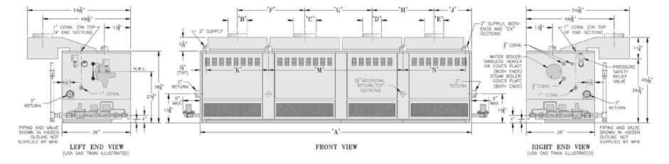
6.DIMENSIONS IN INCHES
|
Jacket |
|
|
|
|
|
|
|
|
|
Top Supply |
|
Supply |
|
|
|
Approx. |
|||
|
|
|
Draft Hood Height, Size and Location |
|
and Rear Return |
|
Gas Conn. |
|
||||||||||||
Boiler |
Overall |
|
|
|
Conn. |
Return Conn. |
No. & Dia. of |
Shipping |
||||||||||||
|
|
|
|
|
|
|
|
|
|
Location |
|
Size Nat. & |
||||||||
Size |
Length |
|
|
|
|
|
|
|
|
|
|
|
Qty & |
Qty. & Size |
Flue Outlets |
Weight |
||||
|
‘A’ |
‘B’ |
‘C’ |
|
‘D’ |
‘E’ |
‘F’ |
‘G’ |
‘H’ |
‘J’ |
‘K’ |
|
‘M’ |
|
‘N’ |
Size |
|
Propane |
|
(LB.) |
|
Dia. |
Dia. |
|
Dia. |
Dia. |
|
|
|
|
|
||||||||||
|
|
|
|
|
|
|
|
|
|
|
|
|
|
|
|
|
||||
|
|
|
|
|
|
|
|
|
|
|
|
|
|
|
|
|
|
|
|
|
5006B |
34 |
9 |
--- |
|
--- |
--- |
--- |
--- |
--- |
17 |
19-3/4 |
|
--- |
|
--- |
(2) 3 |
(2) 3 |
1 |
(1) 9 |
1160 |
|
|
|
|
|
|
|
|
|
|
|
|
|
|
|
|
|
|
|
|
|
5007B |
39-3/8 |
10 |
--- |
|
--- |
--- |
--- |
--- |
--- |
19-3/4 |
32-1/4 |
|
--- |
|
--- |
(2) 3 |
(2) 3 |
1 |
(1) 10 |
1340 |
|
|
|
|
|
|
|
|
|
|
|
|
|
|
|
|
|
|
|
|
|
5008B |
44-3/4 |
12 |
--- |
|
--- |
--- |
--- |
--- |
--- |
22-3/8 |
38-3/8 |
|
--- |
|
--- |
(2) 3 |
(2) 3 |
1 |
(1) 12 |
1525 |
|
|
|
|
|
|
|
|
|
|
|
|
|
|
|
|
|
|
|
|
|
5009B |
50-1/4 |
12 |
--- |
|
--- |
--- |
--- |
--- |
--- |
25-1/8 |
43-3/4 |
|
--- |
|
--- |
(2) 3 |
(2) 3 |
1-1/4** |
(1) 12 |
1720 |
5010B |
55-3/4 |
12 |
--- |
|
--- |
--- |
--- |
--- |
--- |
27-7/8 |
49-1/4 |
|
--- |
|
--- |
(2) 3 |
(2) 3 |
1-1/4 |
(1) 12 |
1895 |
|
|
|
|
|
|
|
|
|
|
|
|
|
|
|
|
|
|
|
|
|
5011B |
61-1/8 |
9 |
9 |
|
--- |
--- |
27-1/4 |
--- |
--- |
17 |
54-3/4 |
|
--- |
|
--- |
(2) 3 |
(2) 3 |
1-1/4 |
(2) 9 |
2085 |
5012B |
66-1/2 |
9 |
10 |
|
--- |
--- |
29-7/8 |
--- |
--- |
19-3/4 |
60-1/8 |
|
--- |
|
--- |
(2) 3 |
(2) 3 |
1-1/4 |
(1) 9, (1) 10 |
2280 |
|
|
|
|
|
|
|
|
|
|
|
|
|
|
|
|
|
|
|
|
|
5013B |
72 |
10 |
10 |
|
--- |
--- |
32-5/8 |
--- |
--- |
19-3/4 |
65-1/2 |
|
--- |
|
--- |
(2) 3 |
(2) 3 |
1-1/4 |
(2) 10 |
2460 |
5014B |
77-1/2 |
10 |
12 |
|
--- |
--- |
35-3/8 |
--- |
--- |
22-3/8 |
71 |
|
--- |
|
--- |
(2) 3 |
(2) 3 |
1-1/4 |
(1) 10, (1) 12 |
2640 |
|
|
|
|
|
|
|
|
|
|
|
|
|
|
|
|
|
|
|
|
|
5015B |
82-7/8 |
12 |
12 |
|
--- |
--- |
38 |
--- |
--- |
22-3/8 |
38-1/4 |
38-1/4 |
|
--- |
(3) 3 |
(2) 3, (1) 2-1/2 |
(2) 1* |
(2) 12 |
2870 |
|
|
|
|
|
|
|
|
|
|
|
|
|
|
|
|
|
|
|
|
|
|
5016B |
88-1/4 |
12 |
12 |
|
--- |
--- |
40-3/4 |
--- |
--- |
25-1/8 |
38-1/4 |
43-5/8 |
|
--- |
(3) 3 |
(2) 3, (1) 2-1/2 |
(1) 1, (1) 1-1/4* |
(2) 12 |
3070 |
|
|
|
|
|
|
|
|
|
|
|
|
|
|
|
|
|
|
|
|
|
|
5017B |
93-3/4 |
12 |
12 |
|
--- |
--- |
43-1/2 |
--- |
--- |
25-1/8 |
43-5/8 |
43-5/8 |
|
--- |
(3) 3 |
(2) 3, (1) 2-1/2 |
(2) 1-1/4* |
(2) 12 |
3265 |
|
|
|
|
|
|
|
|
|
|
|
|
|
|
|
|
|
|
|
|
|
|
5018B |
99-1/4 |
12 |
12 |
|
--- |
--- |
46-1/4 |
--- |
--- |
27-7/8 |
43-5/8 |
49-1/8 |
|
--- |
(3) 3 |
(2) 3, (1) 2-1/2 |
(2) 1-1/4* |
(2) 12 |
3445 |
|
5019B |
104-5/8 |
12 |
12 |
|
--- |
--- |
49 |
--- |
--- |
27-7/8 |
49-1/8 |
49-1/8 |
|
|
(3) 3 |
(2) 3, (1) 2-1/2 |
(2) 1-1/4* |
(2) 12 |
3620 |
|
|
|
|
|
|
|
|
|
|
|
|
|
|
|
|
|
|
|
|
|
|
5020B |
110 |
9 |
9 |
|
12 |
--- |
27-1/4 |
38 |
--- |
27-7/8 |
54-1/2 |
49-1/8 |
|
--- |
(3) 3 |
(2) 3, (1) 2-1/2 |
(2) 1-1/4* |
(2) 9, (1) 12 |
3810 |
|
5021B |
115-1/2 |
9 |
10 |
|
12 |
--- |
29-7/8 |
40-3/4 |
--- |
27-7/8 |
27-3/8 |
32-5/8 |
|
49-1/8 |
(4) 3 |
(2) 3, (2) 2-1/2 |
(2) 1-1/4* |
(1) 9, (1) 10, (1) 12 |
4005 |
|
|
|
|
|
|
|
|
|
|
|
|
|
|
|
|
|
|
|
|
|
|
5022B |
121 |
10 |
10 |
|
12 |
--- |
32-5/8 |
40-3/4 |
--- |
27-7/8 |
32-3/4 |
32-5/8 |
|
49-1/8 |
(4) 3 |
(2) 3, (2) 2-1/2 |
(2) 1-1/4* |
(2) 10, (1) 12 |
4185 |
|
|
|
|
|
|
|
|
|
|
|
|
|
|
|
|
|
|
|
|
|
|
5024B |
131-3/4 |
9 |
10 |
|
10 |
10 |
29-7/8 |
32-5/8 |
32-5/8 |
19-3/4 |
27-3/8 |
65-1/4 |
|
32-3/4 |
(5) 3 |
(2) 3, (3) 2-1/2 |
(2) 1-1/4* |
(1) 9, (3) 10 |
4530 |
|
|
|
|
|
|
|
|
|
|
|
|
|
|
|
|
|
|
|
|
|
|
5026B |
142-3/4 |
10 |
12 |
|
10 |
10 |
35-3/8 |
35-3/8 |
32-5/8 |
19-3/4 |
32-3/4 |
|
70-3/4 |
|
32-3/4 |
(5) 3 |
(2) 3, (3) 2-1/2 |
(2) 1-1/4* |
(3) 10, (1) 12 |
4895 |
|
|
|
|
|
|
|
|
|
|
|
|
|
|
|
|
|
|
|
|
|
|
|
|
|
|
* Dual Manifolds - 5015B thru 5026B |
|
|
|
|
|
|
**1” - |
USA - EI |
|
|
|||||
9
Fig. 1
DIMENSIONAL DATA
SECTION II – GENERAL INFORMATION
1.BOILER INSTALLATION must conform to the requirements of the authority having jurisdiction, or in the absence of such requirements, to:
USA – “National Fuel Gas Code, ANSI Z223.1”.
When required by the authority having jurisdiction, the installation must conform to American Society of Mechanical Engineers Safety Code for Controls and Safety Devices for Automatically Fired Boilers, No. CSD-1.
CANADA – “Installation Codes for Natural and Propane Gas Burning Appliances and Equipment, CAN/CSA-B149 (.1 or .2)”.
DO NOT INSTALL THIS BOILER ON CARPETING.
2.BOILER LOCATION – locate on a level NONCOMBUSTIBLE FLOOR as close as possible to chimney so that vent connection is short and direct.
Boiler must not be installed directly on combustible flooring. A concrete pad is not sufficient to protect combustible flooring.
The boiler shall be installed such that the gas ignition system components are protected from water (dripping, spraying, rain, etc.) during boiler operation and service (circulator replacement, control replacement, etc.).
Do not install boiler where gasoline or other flammable vapors or liquids, or sources of hydrocarbons (i.e. bleachers, cleaners, chemicals, sprays, paint removers, fabric softeners, etc. ) are used or stored.
Refer to table below for minimum clearances, service clearances, and clearances for removal of Tankless Heaters.
3.PROVIDE COMBUSTION AND VENTILATION AIR.
In the USA refer to National Fuel Gas Code, NFPA 54/ANSI Z223. Section 5.3, Air for Combustion and Ventilation. In Canada refer to Natural Gas Installation Code, CAN/CSA-B149.1 – latest edition or Propane Installation Code, CAN/CSA-B149.2 – latest edition. Local code provisions may apply and should be referenced.
Adequate combustion and ventilation air must be provided to assure proper combustion.
a.Determine volume of space (boiler room). Rooms communicating directly with the space, in which the appliances are installed, through openings not furnished with doors, are considered a part of the space.
Volume (ft³) = Length (ft) x Width (ft) x Height (ft)
b.Determine total input of all appliances in the space. Add inputs of all appliances in the space and round the result to the nearest 1000 Btu per hour.
c.Determine type of space.
Divide Volume by Total Input of all appliances in space. If the result is greater than or equal to
50ft³/1000 Btu per hour, then it is considered an unconfined space.
If the result is less than 50 ft³/1000 Btu per hour, then the space is considered a confined space.
d.For boiler located in an unconfined space of a conventionally constructed building, the fresh air infiltration through cracks around windows and doors normally provides adequate air for combustion and ventilation.
e.For boiler located in a confined space or an unconfined space in a building of unusually tight construction, provide outdoor air with the use of two permanent openings which communicate directly or by duct with the outdoors or spaces (crawl or attic) freely communicating with the
outdoors. Locate one opening within 12 inches of top of space. Locate remaining opening within 12 inches of bottom of space. Minimum dimension of air opening is 3 inches. Size each opening per following:
1.Direct communication with outdoors. Minimum free area of 1 square inch per 4,000 Btu per hour input of all equipment in space.
2.Vertical ducts. Minimum free are of 1 square inch per 4,000 Btu per hour input of all
CLEARANCES - From Table below and from dimensional data in Fig. 1, determine BOILER ROOM space necessary for appropriate access to and servicing of Boiler. Consideration should be given to other appliances installed in the same area. Consult with local Building and
Safety Codes for compliance.
|
MINIMUM CLEARANCE - JACKET TO |
RECOMMENDED |
CLEARANCES REQ’D FOR REMOVAL |
|||
|
SERVICE CLEARANCE TO |
|
OF TANKLESS HEATER |
|||
|
COMBUSTIBLE CONSTRUCTION |
|
||||
|
NON-COMBUSTIBLE CONSTRUCTION |
AT-2 |
|
AT-3 |
AT-4 |
|
|
|
|
||||
Left Side |
24” (61 cm) |
18” (Controls) |
27” |
|
32” |
42” |
Right Side |
24” (61 cm) |
18” (Controls) |
27” |
|
32” |
42” |
Front |
24” (61 cm) |
36” (Cleaning-Burner Removal) |
--- |
|
--- |
--- |
Rear |
24” (61 cm) |
36” (Cleaning) |
--- |
|
--- |
--- |
Top |
24” (61 cm) |
---------------------------------------- |
--- |
|
--- |
--- |
10
SECTION II – GENERAL INFORMATION (continued)
equipment in space. Duct cross-sectional area shall be same as opening free area.
3.Horizontal ducts. Minimum free area of 1 square inch per 2,000 Btu per hour input of all equipment in space. Duct cross-sectional area shall be same as opening free area.
Alternate method for boiler located within confined space. Use indoor air if two permanent openings communicate directly with additional space(s) of sufficient volume such that combined volume of all spaces meet criteria for unconfined space. Size each opening for minimum free area of 1 square inch per 1,000 Btu per hour input of all equipment in spaces, but not less than 100 square inches.
4.Louvers and Grilles of Ventilation Ducts
All outside openings should be screened and louvered. Screens used should not be smaller than ¼ inch mesh. Louvers will prevent the entrance of rain and snow.
a.Free area requirements need to consider the blocking effect of louvers, grilles, or screens protecting the openings. If the free area of the louver or grille
is not known, assume wood louvers have 20-25 percent free area and metal louvers and grilles have 60-75 percent free area.
b.Louvers and grilles must be fixed in the open position or interlocked with the equipment to open automatically during equipment operation.
SECTION III – INSTALLATION INSTRUCTIONS
Fig. 2
SINGLE MANIFOLD BASE 5006B
THRU 5014B SECTION BOILERS
1. BASE-BURNER-MANIFOLD ASSEMBLY(S).
a.5006B section thru 5014B section boilers require single base assembly, see Fig. 2.
b.5015B section thru 5026B section boilers require a left and a right base subassembly, see Fig. 3.
Remove Base Assembly(s) From Skid(s)
c.Remove bolts securing Base Assembly(s) to shipping skid(s) and place Base(s) in location where Boiler is to be installed.
d.Join Base Sub-assemblies together (15 section & larger boilers) by first removing upper shipping strip and lower shipping angles from subassemblies. Use (4) ¼”-20 x ¾” MS, nuts and washers to attach subassemblies, see Fig. 3.
e.Attach Front Intermediate Jacket Panel Support Bracket and Lower Rear Intermediate Panel Support Bracket to lower channel on Front Base Frame and Rear Base Frame, respectively, using (4) ¼”-20 x ¾” MS, nuts and washers.
f.Base must be level in both directions and secure on the floor. Shim and grout under Base if necessary.
g.Place cardboard covering over the top of the burner assembly to protect them during the assembly of the boiler sections.
2.CLEAN BOILER SECTIONS inside and out to remove dirt due to shipment and handling.
Open Tie Rod Bundle(s). Open Draw-up Rod Bundle(s).
Open Boiler Assembly Carton(s).
3.SET LEFT END SECTION ON BASE so that locating lugs on bottom of section go inside Front and Rear Base Frames. Slide section on base until these lugs strike High Base End Panel at left end of Base, see Fig. 4. (Note – if High Base End Panel is at right end of Base, section assembly must start with Right End Section). Left end sections are identified by “LEH” cast on section; Right End Sections are identified by “REH” cast on section.
4.CLEAN NIPPLES AND NIPPLE PORTS thoroughly with a de-greasing solvent. Use the Loctite® #592 supplied to lubricate the nipples and nipple ports.
Apply the lubricant to the nipples and nipple ports, then use a brush to disperse it evenly around the nipples and the nipple ports. Use approximately 25 ml of Loctite® #592 per flueway [(1) 7” and (2) 3” nipples and their
(6) corresponding nipple ports]. Use Nipple Gauge furnished – follow instructions included with gauge to set nipples. USE ALL PRECAUTIONS TO AVOID COCKED NIPPLES.
5.PAINTALL GROUND SURFACES of each section with the Sealer Compound furnished.
6.ASSEMBLE CENTER SECTIONS. Refer to Fig. 6 for proper location of Tapped, and sometimes plugged,
11

SECTION III – INSTALLATION INSTRUCTIONS (continued)
Fig. 3
DUAL MANIFOLD BASES - 5015B THRU 5026B SECTION BOILERS
Center Sections on 11 section and larger boilers. THIS
IS IMPORTANT.
a.Carefully join a Center Section with nipples in adjoining section and bump lightly to secure.
b.Run nut approximately 8” on two (2) ¾” draw-up rods of equal length. (Note – more than one set of draw-up rods are furnished on 8 section and larger boilers). Place draw-up channel and one flat washer against nut.
Fig. 4
LEH SECTION ON BASE Fig. 5
ASSEMBLY OF CENTER SECTIONS
12

SECTION III – INSTALLATION INSTRUCTIONS (continued)
13
Fig. 6
ARRANGEMENT OF SECTIONS AND CANOPY(S)
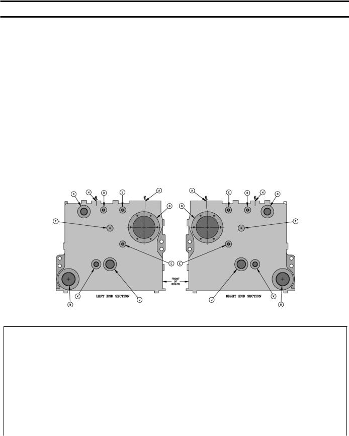
SECTION III – INSTALLATION INSTRUCTIONS (continued)
c.Insert short end of draw-up rod through front & rear nipple ports on both sections, see Fig. 5.
d.Place two (2) flat washers, draw-up channel and a nut on each end of draw-up rods and finger tighten.
e.DRAW UP CENTER SECTION SLOWLYAND EVENLY, tightening each DRAW-UP ROD a little at a time so that sections are equally spaced. KEEP NIPPLES ALIGNED WITH NIPPLE PORTS. If necessary, tap Nipples lightly with a blunt tool or rod to keep Nipples from cocking while Sections are being drawn up. DO NOT DRAW UP SECTION(S) WHEN NIPPLES ARE COCKED. Continue tightening Draw-Up Rods equally until Sections meet iron-to-iron on the ground surface. BUMPING OUTER EDGES OF SECTION WITH WOODEN BLOCK WILL EASE DRAW-UP OPERATION.
f.KEEP DRAW-UP ROD THREADS, NUTS AND WASHERS LUBRICATED with grease or heavy oil to prevent damage to rods and threads and to make assembling easier.
g.Using a pinch bar, insert WOOD WEDGES under last Center Section assembled so as to raise it just above Boiler Base. This will keep the next section to be assembled above the base, thus making it easier to join and draw-up. MOVE WOOD WEDGES FORWARD EACH time a Section has been drawn up.
7.ASSEMBLE REMAINING END SECTION WITH DRAW-UP RODS in a manner similar to that for assembling Center Sections. Remove wedges from under Boiler. Be sure Boiler is aligned and seated on Base.
a.After section assembly is completed install 5/8” tie rods from tie rod bundle through the upper lug holes in the front of Boiler and Lower lug holes in the rear of Boiler sections and tighten until they are finger tight only, to allow for expansion. This is necessary in order to allow clearance for installation of Flue cover plates. Finally, remove ¾” draw-up rods from nipple ports.
Fig. 7
PURPOSE OF TAPPINGS AND THEIR LOCATIONS
PURPOSE OF TAPPINGS 1
Location |
Tapping Per |
Size |
Steam Boilers |
Water Boilers |
|
End Section |
|||||
|
|
|
|
||
A |
1 |
3” |
Supply |
Supply |
|
B |
1 |
3” |
Return |
Return |
|
C2 |
1 |
1-1/2” |
Pressure Operating Control |
Temperature Operating Control (less heater) |
|
(Bushed to 1/4”) |
Bushed to 3/4”; Plug (with heater) |
||||
|
|
|
|||
D |
1 |
1/2” |
Pressure Gauge |
Theraltimeter |
|
E |
2 |
1/2” |
Water Gauge, LWCO & Pressure Limit |
Plug |
|
F |
1 |
3/8” |
Try-Cock (Special Order) |
---- |
|
G3 |
1 |
---- |
Cover Plate |
Cover Plate or Tankless Heater |
|
H |
1 |
1” |
See Note 4 |
See Note 4 |
|
J |
1 |
1-1/2” |
Indirect Water Heater |
---- |
|
Supply or Return |
|||||
|
|
|
|
||
K |
1 |
3/4” |
Indirect Water Heater Limit |
---- |
1Tappings on both end sections are identical - Recommend trim be installed in left end section or on same end as gas train.
2This tapping is used for safety valve and surface blowoff (steam boilers) and safety relief valve (water boilers) on end not equipped with trim.
3Temperature operating control location on tankless heater equipped boilers. Also alternate operating control location, tapped cover plate.
4If using a float type LWCO, feeder or pump controller on a steam boiler that does not use quick connect hook up fittings, install between tappings H and return B. Use opposite return B for system return connection. Water boilers using a probe LWCO must mount probe in supply pipe above boiler without any stop valves.
14
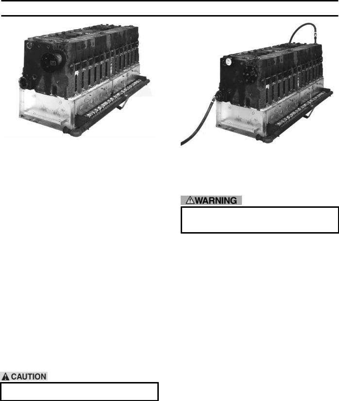
SECTION III – INSTALLATION INSTRUCTIONS (continued)
Fig. 8
INSTALLATION OF BUILT-IN HEATER
Open Steam or Water Trim Carton
8.Use the plugs in this carton to plug tappings in End Sections that will not be utilized on final installation, see Fig. 7.
Open Tankless Heater Carton(s) If Supplied. Open Heater Opening Cover Plate Carton(s).
9.INSTALL BUILT-IN WATER HEATER(S) OR HEATER OPENING COVER PLATE(S), See Fig. 8. Heater may be installed in either End Section or, in some cases, in both End Sections. Heater Opening Cover Plates are used to cover any unused heater openings.
a.Place rubber gasket against surface of plate and align holes.
b.Place washer on each of 3/8” Cap Screws furnished and insert cap screws through plate and gasket. Start all screws in taps before final tightening.
10. HYDROSTATIC TEST, see Fig. 9: After the boiler sections have been assembled, it is essential that the boiler be hydrostatically tested before the canopy, flue cover plates, jacket, or piping is installed.
a.Plug all boiler tappings and fill boiler completely with cold water.
DO NOT install gauge until after hydrostatic testing the boiler. Gauge failure may result.
b.Allcompletedboilersmustsatisfactorilypassthe prescribed hydrostatic test.
(1)STEAM BOILERS: The assembled boiler must be subjected to a hydrostatic test of 45 psig to 55
psig.
Fig. 9
TESTING BOILER ASSEMBLY FOR LEAKS
(2)HOT WATER BOILERS: The assembled boiler must be subjected to a hydrostatic test of 75 psig to 85 psig.
Failure to properly hydrotest all boilers at the correct pressure may result in section assembly failure in operation.
11.EXAMINE BOILER CAREFULLY, INSIDE AND OUTSIDE, to insure against leaks from cocked nipples or through concealed breakage caused in shipping and handling. This precaution is for your protection and will simplify handling of necessary replacements and adjustment claims. After making certain that there are no leaks, drain boiler and remove plugs for boiler trim and other connections.
Open Boiler Sealing Carton.
12.SEAL BETWEEN BOILER SECTIONS AND BASE, see Fig. 10.
a.Push ¾” braided ceramic fibre Rope (furnished) into gap between bottom of End Section and Low Base End Panel until rope touches Front and Rear Base Frames. Place the 1-1/2” x 2” x 5/8” steel spacers between low base panel and section and in front of rope – align holes. Secure section to low base end panel with 3/8”-16 x 2” Cap Screws, washers and nuts.
b.Secure opposite end section to high base end panel with 3/8”-16 x 2” Cap Screws, washers and nuts.
c.Apply Furnace Cement to gaps between section assembly and base to make gas tight seal.
d.Check all joints between Boiler sections and use remaining Furnace Cement or Sealer Compound to make joints gas tight.
15
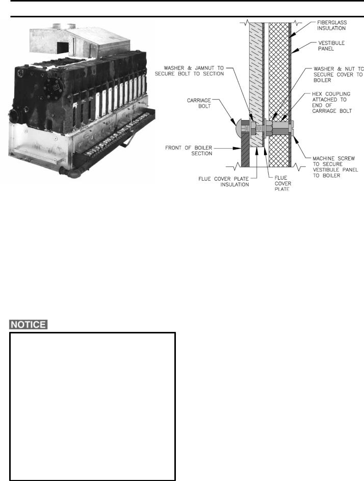
SECTION III – INSTALLATION INSTRUCTIONS (continued)
Fig. 10
SEALING OF BASE, INSTALLATION OF FLUE COVERS AND CANOPIES
13.INSTALL FLUE COVER PLATES over cleanout openings on Front and Rear of Boiler. Use ¼” Carriage Bolts installed at top and bottom of flue openings and secure with washer and jam nut to provide a fixed stud. Install flue cover plates over studs with insulation against Boiler and secure with washers and nuts, see Fig. 11.
14.CONNECT SUPPLYAND RETURN PIPING TO HEATING SYSTEM.
CLEARANCES – Steam and Hot water pipes shall have clearances of at least ½” from all combustible construction.
Before using copper for steam piping, consider the following characteristics of copper piping:
1)high coefficient of thermal expansion can induce mechanical stresses and cause expansion/ contraction noises if not accounted for in the piping system design and installation,
2)high heat transfer rate (heat loss) of uninsulated copper piping must be included in the normal piping and pickup factors used to size the boiler,
3)soldering or brazing pastes and fluxes that end up in the system can cause poor heat transfer, surging, and unsteady water line and wet steam if not thoroughly removed during the boil out procedure and,
4)galvanic corrosion of the adjoining metal may occur due to dissimilar metals in certain water chemistries if dielectric unions are not used.
16
Fig. 11
ATTACHMENT OF FLUE COVERS
a.With Steam Heating System, refer to Fig. 12, 13, 14 or 15.
b.With Forced Circulation HOT WATER HEATING SYSTEMS, see Fig. 16A and 16B. For additional reference, consult I=B=R Installation and Piping Guide No. 250.
NOTE: When Hot Water Heating Boilers are connected to Heating Coils located in Air Handling Units where they may be exposed to refrigerated air circulation, the Boiler Piping System must
be equipped with Flow Control Valves or other automatic means to prevent gravity circulation of the Boiler Water during the cooling cycle.
c.With COMBINATION HEATING AND COOLING (REFRIGERATION) SYSTEMS having the same Distributing Units, Piping and Circulator, See Fig. 17. For additional reference, consult ASHRAE Systems Handbook 2008 Edition.
d.NOTE: Valves must be installed in the supply and return branches to the Heating Boiler and Water Chiller so as to prevent circulation of Chilled Water through the Boiler or Heated Water through the Chiller.
OXYGEN CORROSION:
Oxygen contamination of the boiler water will cause corrosion of the iron and steel boiler components, which can lead to failure. As such, any system must be designed to prevent oxygen absorption in the first place or prevent it from reaching the boiler. Problems caused by oxygen contamination of boiler water are not covered by Burnham’s standard warranty.

SECTION III – INSTALLATION INSTRUCTIONS (continued)
17
Fig. 12
RECOMMENDED STEAM BOILER PIPING, GRAVITY RETURN I OR 2 SUPPLY CONNECTIONS - 5006B THRU 5014B
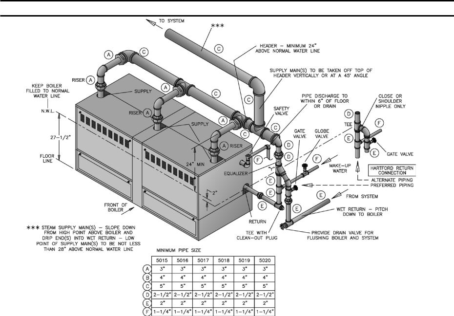
18
SECTION III – INSTALLATION INSTRUCTIONS (continued)
Fig. 13
RECOMMENDED STEAM BOILER PIPING, GRAVITY RETURN 3 SUPPLY CONNECTIONS - 5015B THRU 5020B
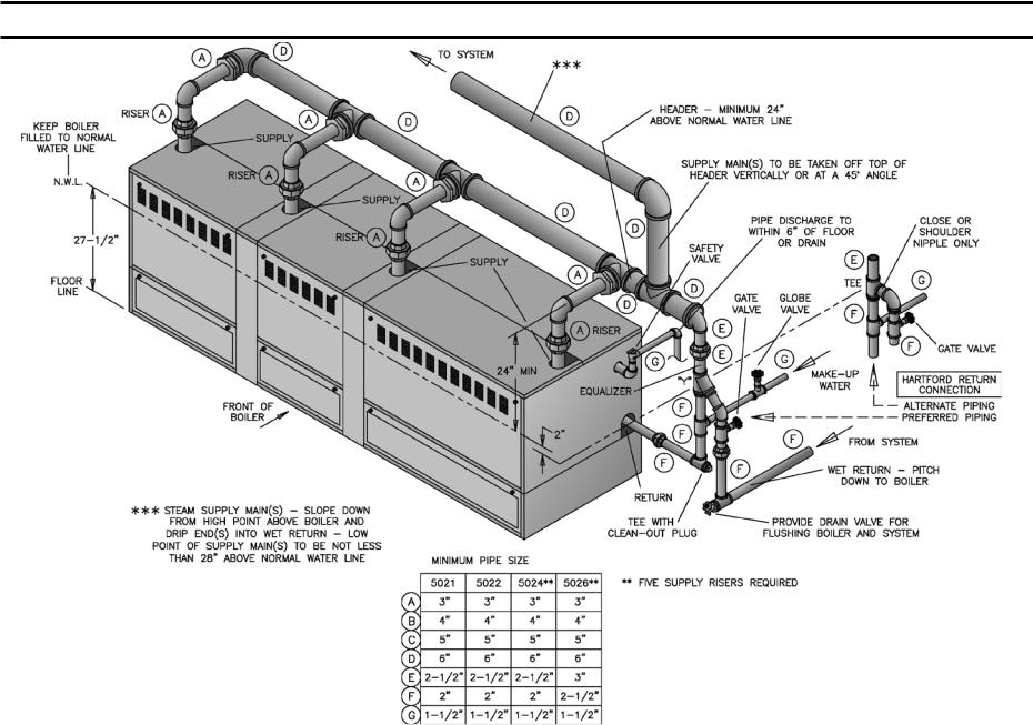
SECTION III – INSTALLATION INSTRUCTIONS (continued)
19
Fig. 14
RECOMMENDED STEAM BOILER PIPING, GRAVITY RETURN 4 OR 5 SUPPLY CONNECTIONS - 5021B THRU 5026B
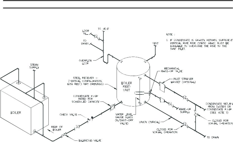
20
SECTION III – INSTALLATION INSTRUCTIONS (continued)
Fig. 15
Typical Steam Piping Arrangement for Boilers with Pumped Condensate Return and Boiler Feed Unit
SECTION III – INSTALLATION INSTRUCTIONS (continued)
21
Fig. 16A |
Fig. 16B |
RECOMMENDED WATER BOILER PIPING |
RECOMMENDED WATER BOILER PIPING |
1 SUPPLY CONNECTION & 1 RETURN CONNECTION |
3 SUPPLY CONNECTIONS & 2 RETURN CONNECTIONS |
SIZES 5006B THRU 5019B |
SIZES 5020B THRU 5026B |
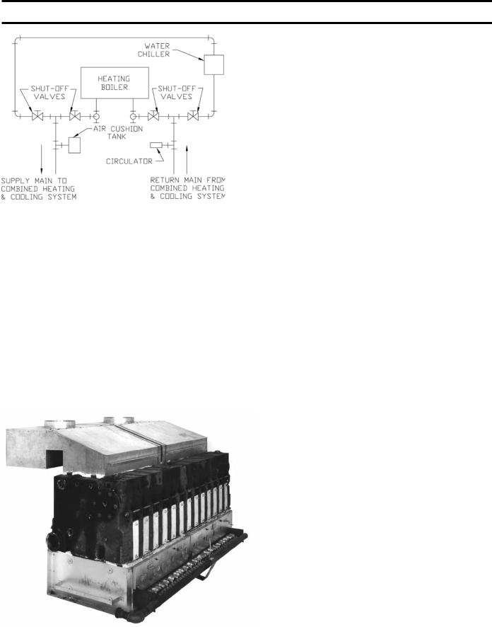
SECTION III – INSTALLATION INSTRUCTIONS (continued)
Fig. 17
RECOMMENDED BOILER PIPING FOR COMBINATION HEATING & COOLING SYSTEMS
There are many possible causes of oxygen contamination such as:
1.Addition of excessive make-up water as a result of system leaks.
2.Absorption through open tanks and fittings.
3.Oxygen permeable materials in the distribution system.
In order to insure long product life, oxygen sources should be eliminated. This can be accomplished by taking the following measures:
Fig. 18
INSTALLATION OF JACKET SUPPORT BRACKETS TO BASE END PANELS
1.Repairing system leaks to eliminate the need for addition of make-up water.
2.Eliminating open tanks from the system.
3.Eliminating and/or repairing fittings which allow oxygen absorption.
4.Use of non-permeable materials in the distribution system.
5.Isolating the boiler from the system water by installing a heat exchanger.
Open Jacket Parts Carton
15.INSTALLATION OF JACKET PARTS COMMON TO ALL BOILER SIZES
1.Attach Lower Jacket End Panel Support Bracket to Base End Panel (Both ends) using ¼”-20 x ½” selftapping screws, see Fig. 2 and 18.
2.Attach Lower Left and Lower Right Jacket End Panels to their respective brackets using #10-32 x ½” self-tapping screws, see Fig. 19.
3.See Fig. 7 “Purpose of Tappings and Their Location” and remove necessary knockouts from Upper Left and from Upper Right Jacket End Panels.
4.Place Upper Right End Panel on top of Lower Right End Panel with lip on bottom of Upper Panel positioned behind Lower Panel. Secure to section using #10-32 x ½” self-tapping screws. Attach Upper Left End Panel in a similar manner, see Fig. 19.
NOTE: FOR INSTALLATION OF THE FRAMEWORK FOR THE LOWER UNCOMMON JACKET PARTS REFER TO THE FOLLOWING:
a.5006B thru 5010B section boilers – Paragraph 16, Fig. 21
b.5011B thru 5026B section boilers – Paragraph 30, Fig. 24, 25 or 26
COMPLETION OF JACKET INSTALLATION – 5006B THRU 5010B SECTION BOILERS
NOTE: Do not tighten any screws until Jacket installation is complete.
INSTALLATION OF LOWER FRAMEWORK
16.With “U” channel facing down, slip upper front channel behind joints formed by End Panels and secure to End Panels using #8 SMS. Position Lower Front Channel so that “U” of channel faces boiler. Slip Lower Front Channel behind Lower End Panels and secure with
#8 SMS. Repeat similar procedure for installation of Upper Rear and Lower Rear Channels.
17.Installation of Vestibule Panel refer to Fig. 20.
22

SECTION III – INSTALLATION INSTRUCTIONS (continued)
Attach Hex Couplings to end of Carriage Bolts which secure flue cover plates.
NOTE: Select Carriage Bolts which line up with holes in the Vestibule Panel.
18.Secure Vestibule Panel to Hex Couplings using ¼”-20 x 3/8” slotted pan head machine screws.
19. Attach rear top Jacket Panel to Upper End Panels using #8 SMS. Refer to Fig. 21.
20. Installation of CanopyDraft Hood 5006B thru 5010B Section Boilers, see Fig. 22. Place Cerafelt strips on top of section assembly next to ledges formed by center sections and next to ledge on end sections. Overlap at corners.
21.Secure Canopy-Draft Hood with 5/16”-18 x 5/8” MS driven into the tapped lugs provided for this purpose on top of the sections. Two screws are required at each end. Refer to Fig. 23.
Fig. 19
INSTALLATION OF JACKET END PANELS
Fig. 20
VESTIBULE ATTACHMENT DIAGRAM
23
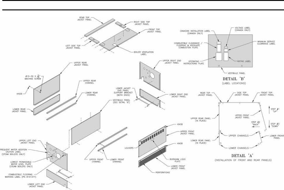
24
SECTION III – INSTALLATION INSTRUCTIONS (continued)
Fig. 21
EXPLODED VIEW OF JACKET 5006B THRU 5010B SECTION BOILERS

SECTION III – INSTALLATION INSTRUCTIONS (continued)
Fig. 22
SECURING OF CANOPY/Draft Hood
25
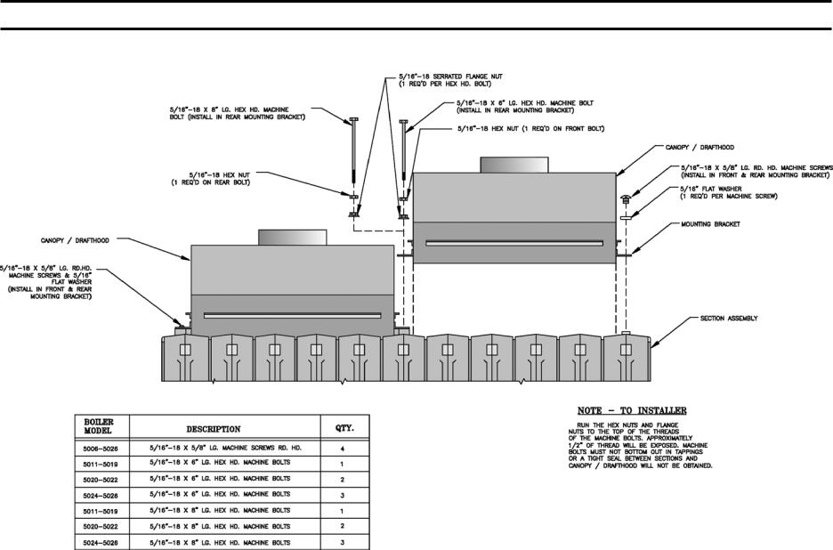
26
SECTION III – INSTALLATION INSTRUCTIONS (continued)
Fig. 23
CANOPY/Draft Hood MOUNTING DIAGRAM

SECTION III – INSTALLATION INSTRUCTIONS (continued)
27
Fig. 24
EXPLODED VIEW OF JACKET 5011B THRU 5019B SECTION BOILERS
SECTION III – INSTALLATION INSTRUCTIONS (continued)
22.Installation of Top Front Jacket Panel
a.Remove knockout for supply piping (right or left for water boilers – both knockouts for steam boilers) refer to recommended boiler piping diagrams in this manual.
b.Attach Top Front Jacket Panel to left and right end Jacket Panel and to Top Flange on the Vestibule Panel using #8 SMS. See Fig. 24.
23.Installation of left and right top side Jacket Panel
a.Remove knockout, right or left, only if needed. (See Fig. 7 for purpose of tappings), secure top side panels to upper end panels with #8 SMS.
24.Install Knobs on the four remaining panels using #10-32 x 3/16” MS.
25.Install Upper Front, Lower Front, Upper Rear and Lower Rear Panels using procedure described in detail “A” of Fig. 25.
Panel with louvers must be at front of boiler for ventilation of vestibule. Panel with perforations must be at front of boiler for ventilation and combustion air.
26.Tighten all sheet metal screws.
27.Install the following plates or labels which are found in the Instruction Envelope. See Fig. 21 or 24 for location.
(1)Rating Label
(2)Operating Instruction Plate (#8 SMS required to fasten)
(3)Combustible Clearance Flooring & Adequate Combustion Plate
(4)Minimum Service Clearance Label (self-adhesive)
(5)Burnham Logo (self-adhesive) – Apply to Top Panel
(6)Boiler Ventilation For Your Safety Label – Apply to Top Panel
(7)Proceed to Paragraph 33 (Steam Boilers) or Paragraph 34 (Water Boilers).
coMPLETION OF JACKET INSTALLATION 5011B THRU 5026B SECTION BOILERS.
28.Paragraphs 1 thru 4 have already been completed. Refer to Paragraph 16 for installation of lower framework.
a.Install Vestibule Panel(s) – refer to Fig. 21 and 24. Attach Hex Couplings to end of Carriage Bolts which secure Flue Cover Plates.
NOTE: Select Carriage Bolts which line up with holes in the Vestibule Panel(s).
b.Attach Intermediate Vestibule Panel(s) to one of the Vestibule Panel(s) using #8 SMS.
c.Secure Left and Right Vestibule Panels to Hex Couplings using ¼”-20 x 3/8” slotted pan head machine screws.
d.Attach the Lower Rear Intermediate Panels to the Lower Rear Intermediate Panel Support Bracket(s) using #10-32 x ½” self tapping screws.
e.Attach the Upper Rear Intermediate Panel(s) to the Lower Rear Intermediate Panel(s) using #8 SMS.
f.Attach Rear Top Intermediate Jacket Panel(s) to Rear Top Left and Right Jacket Panels using #8 SMS.
g.Place Assembled Rear Top Jacket Panel in position and attach to Upper End Panels and Upper Rear Intermediate Panel using #8 SMS.
i.INSTALLATION OF CANOPY-Draft Hood 5011B THRU 5026B SECTION BOILERS – these boilers require two or more Canopy-Draft Hoods – refer to Fig. 6 for proper arrangement. Determine where ends of Canopy-Draft Hood rest on intermediate sections. Place 1” x 14-1/2” Cerafelt strips on top of intermediate section at these locations. Place Cerafelt strips on top of section assembly next to ledges formed by center sections and next to ledges on end sections. Overlap at corner.
ii.SECURE CANOPY-DRAFT HOODS with machine screws and bolts as shown in Fig. 23. Select the type of fastener indicated and drive them into the Tapped Lugs provided for this purpose on top of the sections. Where two
Canopy-Draft Hoods join together, the securing tabs will overlap.
iii.Attach the Front Intermediate Panel to the Front Intermediate Panel Support Bracket(s), using #10-32 x ½” self tapping screws.
29.Installation of Top Front Jacket Panels
a.Remove knockout for supply piping. Refer to recommended boiler piping diagrams in this manual.
b.Attach Top Front Jacket Panels to left and right end
Jacket Panels and also to top flange on the Vestibule
Panel using #8 SMS. Refer to Fig. 25 or 26.
30.Place Top Intermediate Panel(s) on top of left and right Panels, making sure that Front Intermediate Panel(s) is under Top Intermediate Panel(s). Secure Top Intermediate Panel using #8 SMS.
31.Install Knobs on the Upper Front and Upper Rear Panels using #10-32 x 3/16” MS.
Install Upper Front, Lower Front, Upper Rear and Lower Rear Panels using procedure we described in detail “A” of Fig. 25 or 26.
28

SECTION III – INSTALLATION INSTRUCTIONS (continued)
29
Panel with louvers must be at front of boiler for ventilation of vestibule. Panel with perforations must be at front of boiler for ventilation and combustion air.
Fig. 25
EXPLODED VIEW OF JACKET 5020B THRU 5022B SECT. BOILERS

30
SECTION III – INSTALLATION INSTRUCTIONS (continued)
Fig. 26
EXPLODED VIEW OF JACKET 5024B AND 5026B SECT. BOILERS
Panel with louvers must be at front of boiler for ventilation of vestibule. Panel with perforations must be at front of boiler for ventilation and combustion air.
 Loading...