


INSTALLATION, OPERATING AND SERVICE INSTRUCTIONS FOR
V9A SERIES BOILER
3050579
For service or repairs to boiler, call your heating contractor. When seeking information on boiler, provide Boiler Model Number and Serial Number as shown on Rating Label.
Boiler Model Number |
Boiler Serial Number |
Installation Date |
_V9_ _ A |
6_ _ _ _ _ _ _ |
|
|
|
|
Heating Contractor |
|
Type of Fuel |
|
|
|
Address |
|
Phone Number |
|
|
|
|
|
|
Commercial Boilers |
|
||
8142958R19-2/11 |
www.burnhamcommercialcastiron.com |
|
||
|
|
Price - $5.00 |
|
|
|
|
|
|
|


IMPORTANT INFORMATION - READ CAREFULLY
All boilers must be installed in accordance with National, State and Local Plumbing, Heating and Electrical Codes and the regulations of the serving utilities. These Codes and Regulations may differ from this instruction manual. Authorities having jurisdiction should be consulted before installations are made.
In all cases, reference should be made to the following Standards: USA BOILERS
A.Current Edition of American National Standard ANSI/NFPA 31, “Installation of Oil Burning Equipment”, for recommended installation practices.
B.Current Edition of National Fuel Gas Code, NFPA 54/ANSI Z223.1.
C.Current Edition of American National Standard ANSI/NFPA 211, “Chimneys, Fireplaces, Vents, and Solid Fuel Burning Appliances”, For Venting requirements.
D.Current Edition of American Society of Mechanical Engineers ASME CSD-1, “Controls and Safety Devices for Automatically Fired Boilers”, for assembly and operations of controls and safety devices.
E.All wiring on boilers installed in the USA shall be made in accordance with the National Electrical Code and/or Local Regulations.
CANADIAN BOILERS
A.Current Edition of Canadian Standards Association CSA B139, “Installation Code for Oil Burning Equipment", for recommended Installation Practices.
B.The equipment shall be installed in accordance with the current Installation Code for Gas Burning Appliances and Equipment, CSA B149, and applicable Provincial Regulations for the class; which should be carefully followed in all cases.
Authorities having jurisdiction should be consulted before installations are made.
C.All wiring on boilers installed in Canada shall be made in accordance with the Canadian Electrical Code and/or Local Regulations.
DANGER
Indicates an imminently hazardous situation which, if not avoided, will result in death, serious injury or substantial property damage.
CAUTION
Indicates a potentially hazardous situation which, if not avoided, may result in moderate or minor injury or property damage.
WARNING
Indicates a potentially hazardous situation which, if not avoided, could result in death, serious injury or substantial property damage.
NOTICE
Indicates special instructions on installation, operation, or maintenance which are important but not related to personal injury hazards.
NOTICE
This boiler has a limited warranty, a copy of which is printed on the back of this manual.
It is the responsibility of the installing contractor to see that all controls are correctly installed and are operating properly when the installation is complete. The warranty for this boiler is valid only if the boiler has been installed, maintained and operated in accordance with these instructions.

DANGER
DO NOT store or use gasoline or other flammable vapors or liquids in the vicinity of this or any other appliance.
WARNING
Improper installation, adjustment, alteration, service or maintenance can cause property damage, personal injury or loss of life. Failure to follow all instructions in the proper order can cause personal injury or death. Read and understand all instructions, including all those contained in component manufacturers manuals which are provided with the appliance before installing, starting-up, operating, maintaining or servicing this appliance. Keep this manual and literature in legible condition and posted near appliance for reference by owner and service technician.
This boiler requires regular maintenance and service to operate safely. Follow the instructions contained in this manual. Installation, maintenance, and service must be performed only by an experienced, skilled and knowledgeable installer or service agency. All heating systems should be designed by competent contractors and only persons knowledgeable in the layout and installation of hydronic heating systems should attempt installation of any boiler. It is the responsibility of the installing contractor to see that all controls are correctly installed and are operating properly when the installation is completed. Installation is not complete unless a pressure relief valve is installed into the specified tapping located at the rear of appliance - See Section III of this manual for details.
This boiler is suitable for installation on combustible flooring. Do not install boiler on carpeting. Do not operate on floors where heat affected material is below.
Do not tamper with or alter the boiler or controls. Retain your contractor or a competent serviceman to assure that the unit is properly adjusted and maintained.
Clean boiler at least once a year - preferably at the start of the heating season to remove soot and scale. The inside of combustion chamber should also be cleaned and inspected at the same time.
Have Burner and Controls must be checked at least once a year or as may be necessitated. Do not operate unit with jumpered or absent controls or safety devices.
Do not operate unit if any control, switch, component, or device has been subject to water.
Returnwatercannotbelowerthan 135°Fforprolongedperiodsoftime. Operationundertheseconditionswill result in sustained condensing within the combustion chamber and potentially reduce boiler longevity. In addition, the return water cannot be introduced into the boiler if it is more than 40°F less than the idle boiler temperature. Continued operation under these conditions may result in premature boiler failure through thermal shock.
Example: A boiler that has been idle for some time since the last heat demand cycle may have it’s boiler water temperature reduced to 150°F. The return temperature from the next zone activation cannot be less than 110°F.
If the above conditions exist, an RTC (or similar type of control) system must be installed to protect the boiler from sustained condensing operation and thermal shock. See separate RTC Manual, P/N 8146382.

WARNING
Appliance materials of construction, products of combustion and the fuel contain alumina, silica, heavy metals, carbon monoxide, nitrogen oxides, aldehydes and/or other toxic or harmful substances which can cause death or serious injury and which are known to the state of California to cause cancer, birth defectsandotherreproductiveharm. Alwaysusepropersafetyclothing,respiratorsandequipmentwhen servicing or working nearby the appliance.
This boiler contains very hot water under high pressures. Do not unscrew any pipe fittings nor attempt to disconnect any components of this boiler without positively assuring the water is cool and has no pressure. Always wear protective clothing and equipment when installing, starting up or servicing this boiler to prevent scald injuries. Do not rely on the pressure and temperature gauges to determine the temperature and pressure of the boiler. This boiler contains components which become very hot when the boiler is operating. Do not touch any components unless they are cool.
This appliance must be properly vented and connected to an approved vent system in good condition. Do not operate boiler with the absence of an approved vent system.
This boiler needs fresh air for safe operation and must be installed so there are provisions for adequate combustion and ventilation air.
The interior of the venting and air intake systems must be inspected and cleaned before the start of the heating season and should be inspected periodically throughout the heating season for any obstructions. Clean and unobstructed venting and air intake systems are necessary to allow noxious fumes that could cause injury or loss of life to vent safely and will contribute toward maintaining the boiler's efficiency.
This boiler is supplied with controls which may cause the boiler to shut down and not re-start without service. If damage due to frozen pipes is a possibility, the heating system should not be left unattended in cold weather; or appropriate safeguards and alarms should be installed on the heating system to prevent damage if the boiler is inoperative.
This boiler is designed to burn No. 2 fuel oil, natural and/or LP gas only. Do not use gasoline, crankcase drainings, or any oil containing gasoline. Never burn garbage or paper in this boiler. Do not convert to any solid fuel (i.e. wood, coal). Do not convert to any gaseous fuel (i.e. natural gas, LP). All flammable debris, rags, paper, wood scraps, etc., should be kept clear of the boiler at all times. Keep the boiler area clean and free of fire hazards.
Always keep the oil supply valve shut off if the burner is shut down for an extended period of time.
Probe and float type low water cutoff devices require annual inspection and maintenance. Refer to instructions in Section V, Paragraph C for inspection and cleaning instructions.
NOTICE
All V9A Series cast iron boilers are designed, built, marked and tested in accordance with the ASME Boiler and Pressure Vessel Code, Section IV, Heating Boilers. An ASME Data Label is factory applied to each V9A jacket, which indicates the boiler Maximum Allowable Working Pressure (MAWP). Each cast iron section is permanently marked with the MAWP listed on the boiler’s ASME Data Label. Those values for the V9A are as follows:
MAWP, Steam - 15 psi MAWP, Water (USA) - 80 psi
MAWP, Water (Canada) - 45 psi
It is common and acceptable practice to install these boilers in lower pressure systems, below the boiler MAWP. Therefore, Burnham offers safety relief valves set at or below the MAWP of the boiler. See Table 1 for available safety relief valve set pressures.

TABLE OF CONTENTS |
|
SECTION I - GENERAL INFORMATION |
|
Dimensional Information ............................................................................................................................................... |
8 |
Ratings/Data ................................................................................................................................................................... |
9 |
Locating the Unit .......................................................................................................................................................... |
10 |
Air Supply/Venting........................................................................................................................................................ |
11 |
SECTION II - CAST IRON BLOCK ASSEMBLY (knockdown Only) |
|
Assembly of Sections, Manual Draw-up ..................................................................................................................... |
14 |
Assembly of Sections, Hydraulic Draw-up .................................................................................................................. |
17 |
Hydrostatic Test ............................................................................................................................................................ |
18 |
SECTION III - INSTALLATION INSTRUCTIONS |
|
Knockdown |
|
Canopy ......................................................................................................................................................................... |
20 |
Flue Cover Plates ......................................................................................................................................................... |
23 |
Rear Observation Port Cover........................................................................................................................................ |
24 |
Inspect All Boiler Seals................................................................................................................................................. |
24 |
Jacket Assembly ........................................................................................................................................................... |
24 |
Burner Mounting Plate / Burner Adapter Plate ............................................................................................................ |
26 |
Steam Trim ................................................................................................................................................................... |
27 |
Water Trim .................................................................................................................................................................... |
27 |
Burner Installation ........................................................................................................................................................ |
28 |
Package Boilers |
|
Preparation for Installation............................................................................................................................................ |
28 |
Common Installation Requirements |
|
Boiler Piping - Water Heating Applications ................................................................................................................. |
29 |
Boiler Piping - Steam Heating Applications................................................................................................................. |
30 |
Boiler Piping - Domestic Hot Water (DHW) Applications........................................................................................... |
39 |
Tankless Heater Piping ................................................................................................................................................. |
40 |
Electric Wiring.............................................................................................................................................................. |
44 |
SECTION IV - OPERATING INSTRUCTIONS |
|
Filling System............................................................................................................................................................... |
45 |
Adjusting Controls ....................................................................................................................................................... |
45 |
Adjusting Burner .......................................................................................................................................................... |
46 |
Test Controls ................................................................................................................................................................ |
46 |
Initial Cleaning, Steam Boilers .................................................................................................................................... |
46 |
Initial Cleaning, Water Boilers ..................................................................................................................................... |
47 |
Frequent Water Addition .............................................................................................................................................. |
48 |
Oxygen Corrosion......................................................................................................................................................... |
48 |
SECTION V - SERVICE INSTRUCTIONS |
|
Cleaning Boiler Heating Surfaces ................................................................................................................................ |
49 |
Maintenance of Low Water Cutoff Devices ................................................................................................................. |
50 |
Checking Burner & Controls........................................................................................................................................ |
51 |
Lubrication.................................................................................................................................................................... |
51 |
General Maintenance Considerations........................................................................................................................... |
51 |
Attention to Boiler While Not in Operation.................................................................................................................. |
51 |

TABLE OF CONTENTS - Continued |
|
SECTION VI - BURNER SPECIFICATIONS |
|
Beckett Burners (Table V)............................................................................................................................................. |
52 |
Power Flame Burners (Table VI).................................................................................................................................. |
53 |
Webster Burners (Table VII)......................................................................................................................................... |
54 |
Carlin Burners (Table VIII)........................................................................................................................................... |
55 |
SECTION VII - REPAIR PARTS |
|
Customer Service Contact Information......................................................................................................................... |
55 |
Jacket Assembly ........................................................................................................................................................... |
56 |
Bare Boiler Assembly................................................................................................................................................... |
58 |
Steam/Water Trim......................................................................................................................................................... |
61 |
WARRANTY........................................................................................................................................................ |
Rear Cover |
Section I - General Information
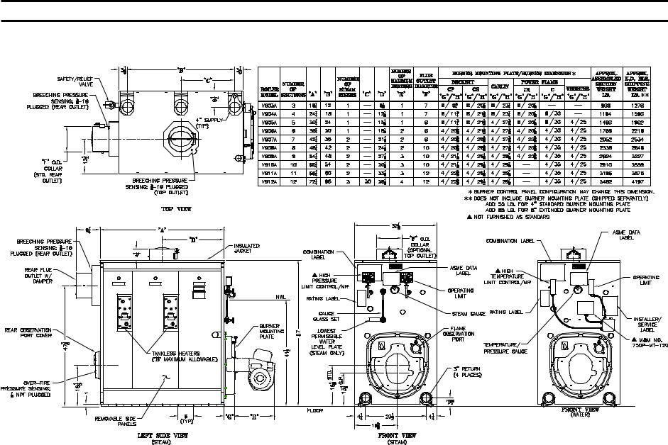
Figure 1: Dimensional Information

Table I: Boiler Ratings / Data
(1) |
|
|
|
(2) |
|
|
|
|
|
(3) |
(4) |
|
|
|
|
|
|
|
|
I=B=R |
|
|
|
I=B=R |
Heating |
New |
Pressure |
Water Content |
Boiler Weight |
I=B=R |
|||||
|
|
Net I=B=R Rating |
Surface |
||||||||||||||
Boiler |
Horse- |
Gross |
Burner Input |
Firebox |
in Firebox |
(Gal.) |
w/Water (Lbs.) |
Vent |
|||||||||
|
|
|
(Sq. Ft.) |
||||||||||||||
Model |
Power |
Output |
|
|
|
|
|
Volume |
(In. Wtr. |
|
|
|
|
Dia. |
|||
Sq. Ft. |
MBH |
MBH |
Oil |
Gas |
|
|
|
|
|
|
|||||||
|
|
(MBH) |
Steam |
Water |
(Cu. Ft.) |
Clmn.) |
Steam |
Water |
Steam |
Water |
(In.) |
||||||
|
|
|
Steam |
Steam |
Water |
(GPH) |
(MBH) |
|
|
|
|
|
|
|
|
|
|
|
|
|
|
|
|
|
|
|
|
|
|
|
|
|
|
|
|
V903A |
10.3 |
347 |
1083 |
260 |
302 |
3.1 |
447 |
34.2 |
37.0 |
3.2 |
.33 |
44.5 |
66.0 |
1439 |
1618 |
7 |
|
|
|
|
|
|
|
|
|
|
|
|
|
|
|
|
|
|
|
V904A |
14.4 |
483 |
1508 |
362 |
420 |
4.2 |
606 |
48.6 |
54.3 |
4.8 |
.38 |
53.0 |
75.0 |
1811 |
1995 |
7 |
|
|
|
|
|
|
|
|
|
|
|
|
|
|
|
|
|
|
|
V905A |
19.3 |
646 |
2021 |
485 |
562 |
5.6 |
808 |
63.0 |
71.5 |
6.4 |
.31 |
61.5 |
84.0 |
2184 |
2372 |
8 |
|
|
|
|
|
|
|
|
|
|
|
|
|
|
|
|
|
|
|
V906A |
24.1 |
808 |
2525 |
606 |
703 |
7.0 |
1010 |
77.5 |
88.8 |
7.9 |
.38 |
70.0 |
93.0 |
2557 |
2749 |
8 |
|
|
|
|
|
|
|
|
|
|
|
|
|
|
|
|
|
|
|
V907A |
28.6 |
959 |
2996 |
719 |
834 |
8.3 |
1198 |
91.9 |
106.0 |
9.5 |
.36 |
78.5 |
102.0 |
2930 |
3126 |
8 |
|
|
|
|
|
|
|
|
|
|
|
|
|
|
|
|
|
|
|
V908A |
33.2 |
1110 |
3471 |
833 |
965 |
9.6 |
1386 |
106.3 |
123.3 |
11.0 |
.35 |
87.0 |
111.0 |
3303 |
3503 |
10 |
|
|
|
|
|
|
|
|
|
|
|
|
|
|
|
|
|
|
|
V909A |
10.1 |
1342 |
4225 |
1014 |
1167 |
11.6 |
1674 |
120.7 |
140.5 |
12.6 |
.35 |
95.5 |
120.0 |
3676 |
3880 |
10 |
|
|
|
|
|
|
|
|
|
|
|
|
|
|
|
|
|
|
|
V910A |
45.6 |
1528 |
4867 |
1168 |
1329 |
13.2 |
1905 |
135.1 |
157.8 |
14.2 |
.40 |
104.0 |
129.0 |
4048 |
4257 |
10 |
|
|
|
|
|
|
|
|
|
|
|
|
|
|
|
|
|
|
|
V911A |
51.2 |
1714 |
5513 |
1323 |
1490 |
14.8 |
2136 |
149.5 |
175.0 |
15.7 |
.45 |
112.5 |
138.0 |
4421 |
4634 |
12 |
|
|
|
|
|
|
|
|
|
|
|
|
|
|
|
|
|
|
|
V912A |
56.8 |
1900 |
6142 |
1474 |
1652 |
16.4 |
2367 |
164.0 |
192.3 |
17.3 |
.49 |
121.0 |
147.0 |
4794 |
5011 |
12 |
|
|
|
|
|
|
|
|
|
|
|
|
|
|
|
|
|
|
|
(1)Type of Build Prefix: K = Knockdown, A = Knockdown w/Assembled Sections, P = Packaged, F = Packaged and Firetested Trim Suffix: S = Steam Boiler, W = Water Boiler
Fuel Suffix: N = Natural Gas, P = LP Gas, O = Oil, C = Natural Gas/Oil, D = LP Gas/Oil, M - Less Burner Burner Suffix: B = Beckett, C = Carlin, J = Power Flame JR, P = Power Flame C, W = Webster, L = Less Burner
(2)I=B=R net ratings shown are based on piping and pick-up allowances which vary from 1.333 to 1.289 for steam and 1.15 for water. Consult manufacturer for installations having unusual piping and pick-up requirements, such as intermittent system operation, extensive piping systems, etc. The I=B=R burner capacity in GPH is based on oil having a heat value of 140,000 BTU per gallon.
(3)Firebox volume does not include added volume of 8” extended burner mounting plate (BMP). If 8” BMP is specified (refer to Figure 1), add 0.7 cu. ft. to volume listed above.
(4)Boiler ratings are based on 12.5% CO2 (oil) and 9.7% CO2 (natural gas), + .10” (inches) water column pressure at boiler flue outlet. Ratings shown above apply at altitudes up to 1000 feet on oil and 2000 feet on gas.
For altitudes above those indicated, the ratings should be reduced at the rate of 4% for each 1000 feet above sea level.
Safety (Relief) Valve Set Pressure: USA Steam Boiler - 15 PSI, USA Water Boiler - 50 PSI
Optional USA Water Boiler - 30 PSI, 80 PSI (special order)
Canadian Steam Boiler - 15 PSI, Canadian Water Boiler - 45 PSI
Optional Canadian Water Boiler - 30 PSI (special order)

SECTION I - GENERAL INFORMATION (Continued)
A.INSPECT SHIPMENT carefully for any signs of damage.
1.ALL EQUIPMENT is carefully manufactured, inspected and packed. Our responsibility ceases upon delivery of crated boiler to the carrier in good condition.
2.ANY CLAIMS for damage or shortage in shipment must be filed immediately against the carrier by the consignee. No claims for variances from, or shortage in orders, will be allowed by the manufacturer unless presented within sixty (60) days after the receipt of goods.
B.LOCATE THE UNIT
1.RECOMMENDED SERVICE CLEARANCE
-Locate the unit in the boiler room so as to
provide ease of venting and adequate clearance for maintenance, serviceability, and installation of piping. Refer to Figure 1 for boiler dimensional data.
FRONT — Provide 43” service clearance for removal, maintenance, and servicing of burner and controls.
REAR — Provide a minimum clearance from the boiler jacket for access to flame observation port, rear flue damper and vent piping, relief valve, and boiler return piping. See Table III.
LEFT SIDE — Provide a minimum clearance from the boiler jacket of 26” for cleaning of flueways and installation and removal of tankless heater(s).
RIGHT SIDE — Provide a minimum clearance from the boiler jacket of 12”.
TOP — Provide a minimum clearance from the boiler jacket of 24”
NOTICE
Recommended clearance for service may be reduced to minimum clearance to combustible material. However, increased service and maintenance difficulty will result.
WARNING
Boiler is suitable for installation on combustible floor. Do not install boiler on carpeting.
Floor constructionshouldhave adequate load bearing characteristics to bear the weight of the boiler filled with water (see Table 1). A boiler foundation similar to the one shown in Figure 2 is recommended if the boiler room floor is weak or uneven or if a water condition exists.
2.FOR MINIMUM CLEARANCES to combustible materials, See Table II.
3.PROVIDE ADEQUATE FOUNDATION for the unit. Refer to Figure 2.
Table II: Minimum Clearances To Combustible
Materials (Inches)
Boilers with Top Flue Outlet
|
Boilers with Rear Flue Outlet |
|||
A |
B |
C |
D |
E |
Above |
Front |
Rear |
Sides |
Vent Connector |
6 |
24 |
6 |
6 |
18 |
*See Table III for Recommended Service Clearance to access rear of boiler
NOTES:
1.Listed clearances comply with American National Standard ANSI/NFPA 31, Installation of Oil Burning Equipment.
2.V9A Series boilers can be installed in rooms with clearances from combustible material as listed above. Listed clearances cannot be reduced for alcove or closet installations.
3.For reduced clearances to combustible material, protection must be provided as described in the above ANSI/NFPA 31 Standard.
Table III: Recommended Rear Service Clearance
Flue |
Top |
Rear Flue Outlet |
|
Outlet |
Flue |
Combustible |
Non-Combustible |
Size |
Outlet |
Surfaces |
Surfaces |
7” Dia. |
18” |
37” |
22” |
8” Dia. |
|
38” |
23” |
10” Dia. |
|
40” |
25” |
12” Dia. |
|
43” |
28” |
10
Figure 2: Boiler Foundation
WARNING
Failure to supply adequate air to the boiler will result in unsafe boiler operation.
C.PROVIDE AIR SUPPLY AND VENTILATION to accommodate proper combustion.
For commercial and industrial equipment, permanent facilities for supplying an ample amount of outside air shall be provided in accordance with the following.
For boiler rooms adjacent to outside walls, and where combustion air is provided by natural ventilation from the outside, there shall be a permanent air supply inlet having a total free area of not less than 1 sq. inch per 4,000 Btu per hr. (35 sq. inch per gallon per hour) (5.5 cm2 per kw.) of total input rating of the burner or burners and in no case less than 35 sq. inch (0.425m2).
For boiler rooms not adjacent to outside walls, the combustion air shall be supplied in a manner acceptable to the authority having jurisdiction.
1.In the absence of local requirements, the confined space shall be provided with two permanent openings, one in or near the top of the room and one near the bottom. The openings shall communicate by means of ducts, with the outdoors or to such spaces (crawl or attic) that communicate with the outdoors.
a.Where communicating by means of vertical ducts, each opening shall have a free area of not
less than 1 sq. inch per 4,000 Btuh (35 sq. inch per gph) (5.5 cm2 per kw) of total input rating of all appliances in the enclosure.
b.If horizontal ducts are used, each opening shall have a free area of not less than 1 sq. inch
per 2,000 Btuh (70 sq. inch per gph.) (11 cm2 per kw) of total input of all appliances in the enclosure.
D.CHIMNEY OR VENT
NOTICE
When a V9A gas fired boiler is connected to a venting system that is designed so that it will operate under a negative pressure, the use of Type C, B, or other manufactured vent systems designed for negative pressure is acceptable.
When a V9A oil fired or combination gas/oil fired boiler is connected to a venting system that is designed so that it will operate under a negative pressure, the use of Type C, L or other manufactured vent systems designed for negative pressure is acceptable.
Unlined masonry chimneys are not acceptable. Lined masonry chimneys are acceptable with the appropriate vent connectors using materials described above.
11
WARNING
When a V9A gas fired boiler is connected to a venting system that is designed so that it will operate under a positive pressure, manufactured vent systems, designed and approved for positive pressure application per UL1738, must be used (for example, Van-Packer model CS, Protech Model FasNSeal / FasNSeal
W2, Heatfab Saf-T-Vent or equivalent).
When a V9A oil fired or combination gas/oil fired boiler is connected to a venting system that is designed so that it will operate under a positive pressure, manufactured vent systems, designed and approved for positive pressure application, must be used (for example, Selkirk Metalbestos Model PS / IPS,
Van-Packer Model ES or equivalent).
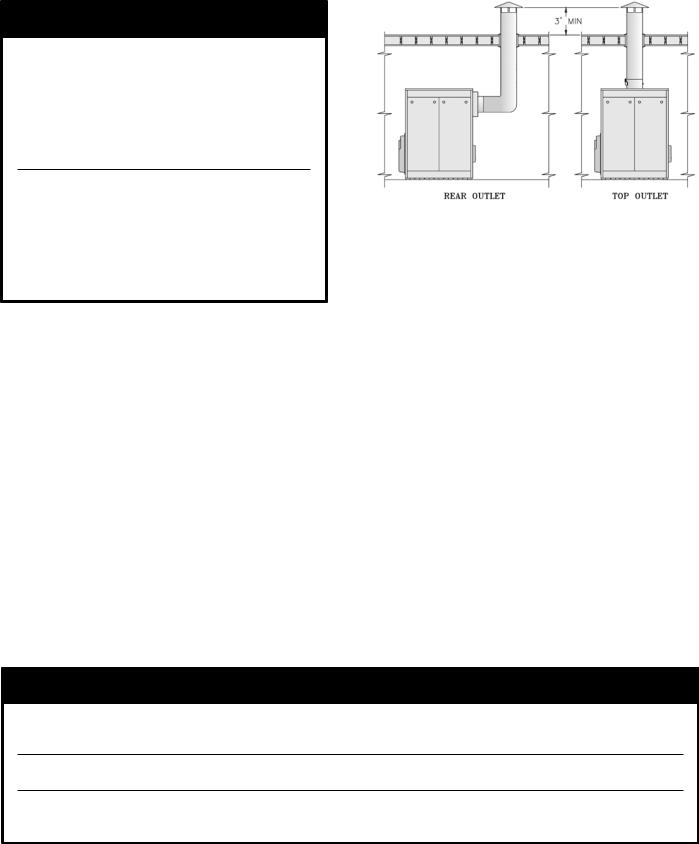
The V9A Series boiler is designed for forced draft firing and may be used with a conventional natural draft stack (15’ minimum height) or a stub vent, sometimes called a diesel stack (see Figure 3a). See Table I for the proper vent outlet size. For low silhouette vent terminations, see Figure 3b. Draft controls are not normally required, although they may be used on installations where a natural draft stack is used or on multiple boiler installations with a common stack. The boiler is provided with a breeching damper, which should be adjusted to maintain a positive pressure of 0.1” W.C. in the vent connector box during burner high fire operation (see breeching pressure sensing port in
Figure 1).
Figure 3a: Typical Arrangement for Stub Vent
If the venting system is designed for positive or forced draft venting, the boiler, vent connector and stack will operate under positive pressure. Gas tight vent systems designed for pressure systems must be used to prevent flue by-product leakage. The vent height is usually limited to prevent negative draft, typically three (3) feet above the roof line (see Figure 3a). The damper shall be adjusted to maintain a positive pressure of 0.1” W.C. in the vent connector box during burner high fire operation (see breeching pressure sensing port in
Figure 1).
If the venting system is designed for negative pressure (natural draft), the boiler still operates with positive pressure in the chamber and up to the fixed damper on the flue collar. However, if the venting system is larger than what is required, the stack will provide a surplus draft (or negative pressure) that may require the use of a barometric damper to maintain the positive 0.1” W.C. pressure at the flue outlet. Multiple forced draft boiler stacks should always be designed as negative to ensure the products of combustion do not exit a boiler that is not firing.
WARNING
Venting instructions are recommendations only. Consult a venting expert on the design of a specific vent system for your application. The ASHRAE Venting Guide and The National Fuel Gas Code, NFPA 54 should be considered in all venting systems.
Conventional vent material may not be suitable for the application. Flue gases can leak carbon monoxide from the joints on these materials and can result in severe personal injury or death.
Installations having long horizontal runs or an excessive amount of tees or elbows will restrict the flow of combustion gases and can result in condensation, flue gas leakage of carbon monoxide, resulting in severe personal injury or death.
12
A |
B |
C |
RAIN CAP |
“A” CAP |
|
TEE TYPE |
RIGHT |
|
RIGHT |
|
RIGHT |
|
||
|
|
|
|
|
D |
E |
90° |
ELBOW
UP or DOWN
WRONG
WRONG
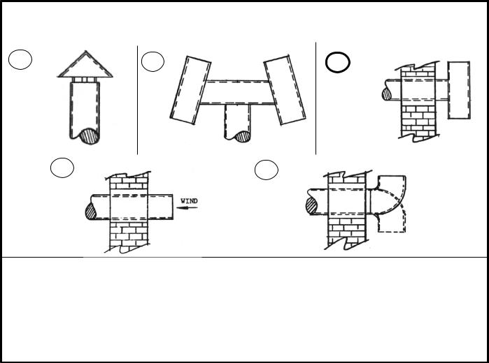
VENT SIZING - Area must be the same as or greater than the boiler breeching (Smoke Outlet). A barometric damper may be required on installations with a high draft condition.
FAULTY BOILER BURNER OPERATION
1.If improper vent is suspected, remove pipe at breeching and operate boiler. This will determine if excessive down draft, blocked or restricted flue, etc. is causing the problem.
2.If using type shown in A above, be sure cap is raised sufficiently above main pipe to allow flue gases to vent unimpeded.
3.A popular type cap is shown in B.
4.The tee is frequently used as shown in C.
5.D and E should not be used due to possible fluctuations in back pressure.
Figure 3b: Vents — Faults & Suggestions
Typical Vents that are used on Forced Draft Boilers, on Low Silhouette Buildings
13
SECTION II - CAST IRON BLOCK ASSEMBLY
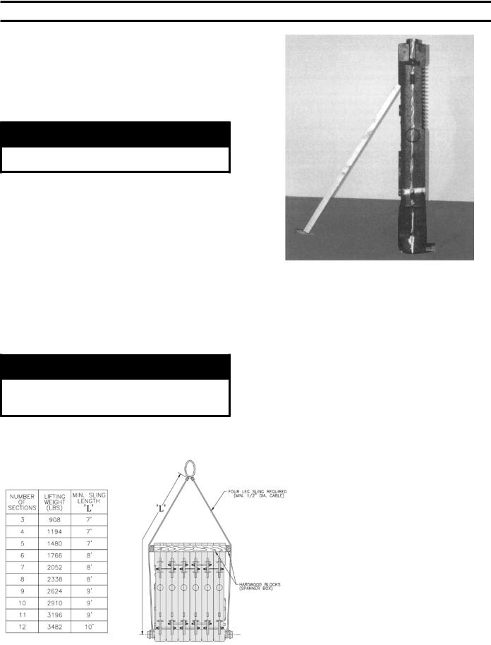
A.FACTORY ASSEMBLED SECTIONS — If the boiler was ordered with factory assembled sections, the assembly should be set in the proper location as outlined in Section I. Lifting arrangement and weights are given in Figure 4.
1.Proceed to Paragraph C of this Section, “HYDROSTATIC TEST”.
CAUTION
Boiler sections must be drawn-up on perfectly level surface or improper assembly may result.
B.FIELD ASSEMBLED SECTIONS — If the boiler was ordered to be field assembled, follow the assembly procedure outlined on the following pages.
1.ASSEMBLY OF SECTIONS (MANUAL DRAWUP)
These sections are designed to be drawn together, one section at a time, using the 9¾” long draw-up rods (provided) and ordinary hand tools.
Tools required:
(1) ¾” Drive Ratchet
(1) 1-1/16” Socket
(1) 1-1/16” Combination or Open End Wrench
(1) Container of grease, oil or other appropriate lubricant.
CAUTION
When assembling sections without hydraulic draw-up equipment, never assemble more than one section at a time.
a.Place the rear section in its approximate final position, as outlined in Section I, and support it with a suitable prop and wedges. See Figure 5.
Figure 4: Lifting Instruction
Figure 5: Positioning of Back Section
b.On size V903A only— Open target wall carton, apply Silastic to back of target wall and secure target wall to rear section.
c.Clean the groove in the ground joint along the edge of the section with the wire brush.
d.Open the Boiler Assembly Carton(s) and remove the bottle of adhesive. Using the dauber supplied in the bottle, apply the adhesive to the groove.
Be sure to use enough adhesive to sufficiently coat the entire groove surface. If so desired, a multi-purpose spray adhesive (supplied by others) may be used instead. HOWEVER, GREAT CARE MUST BE TAKEN TO ENSURE THAT THE ADHESIVE DOES NOT COME IN CONTACT WITH THE NIPPLES OR NIPPLE PORTS.
e.While the adhesive is becoming tacky, clean nipples and nipple ports thoroughly with a degreasing solvent. Use the Loctite #592 provided to lubricate the nipples and nipple ports. Apply the lubricant to the nipples and nipple ports, then use a brush to disperse it evenly around the nipples and the nipple ports. Use approximately
25 ml of Loctite #592 per flueway [(1) 7” and
(2) 3” nipples and their (6) corresponding nipple ports].
f.Drive nipples squarely into section using block of wood and hammer, or preferably, an aluminum head hammer. (Burnham offers a Polyethylene Block for setting the nipples, part number 8052601). Place block over entire nipple edge and hit the wood with the hammer.
14

WARNING
Nipples must be driven in evenly and to the proper depth to assure tight joints. Most nipple leaks are caused by tilted or cocked nipples.
DO NOT use steel/iron head hammer to drive nipples without using a wood block. Nipple damage may result.
g.A special nipple setting gauge is provided for the nipples. Gauge nipple at 90° angles to insure that it is driven to the proper depth into the nipple opening (nipple port). Cut-out in gauge must rest on nipple, with legs of gauge touching finished face of section, when nipple is properly driven. See Figure 6.
Figure 6: Setting of Nipples
h.Remove a 96” length of fiberglass rope from the assembly carton. Starting with the area around the upper 7” nipple port, firmly press the rope into the groove, so that the adhesive holds it in place. (If more than 25 minutes have passed since the adhesive was applied, it may be necessary to reapply.) Continue to affix the rope to the groove in this fashion around the perimeter of the section. Make sure that the rope does not droop or hang outside of the groove. When the end of the groove is reached, cut off the excess rope. Push the length of excess rope into the groove at the top corner of the section face (opposite of the 7” nipple port.) Cut off and discard any remaining rope after groove is filled.
See Figure 7.
Figure 7: Affixing the Fiberglass Rope
NOTICE
The sections must be assembled according to the arrangement shown to ensure proper operation, proper assembly of canopy, jacket and alignment of piping and tankless heaters with jacket knockouts. Start with the back section and work towards the front.
i.From the “Section Arrangement” chart, select the next section according to the “Identification
Code” at the top of the chart. See Figure 8. Use a wire brush to clean the groove in the face
of the next section. Then, using a cartridge of RTV 6500 or RTV 736 sealant in a caulking gun, fill the groove in this section with silastic sealant.
Touch-up any missed spots before draw-up. Touch-up after draw-up has no value.
WARNING
Sections must be drawn-up tight immediately afterproperlyapplyingsealantforbestresults. Although sections may be joined within two
(2) hours of applying sealant, humidity and temperature affect cure time. If a “thick skin” has been formed on the sealant bead, remove and re-apply sealant.
Sealant must be properly applied toALLboiler joints. Failure to properly seal the boiler joints will result in combustion gas leaks through the joint. DO NOT operate boiler with combustion gas leaks.
15
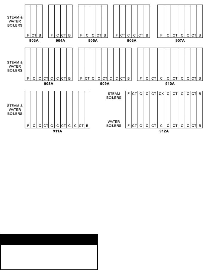
NOTES: FOR BOILERS LESS TANKLESS HEATER, REPLACE THE "CT" SECTIONS WITH "C" SECTIONS.
Figure 8: V9A Section Arrangement
j.Clean and lubricate nipple ports on next section to be assembled and place on nipples previously installed in rear section. To facilitate assembly, it is advisable to enter the upper nipple first in its port. Then enter the lower nipples in their respective ports. If necessary, place a lifting bar (crowbar) under the center of the section and lift the nipple port onto the upper nipple.
k.Drive sections in place with a heavy block of wood, striking blows as squarely as possible over nipple port.
l.The large draw-up rod lugs with dual holes are cast in the four (4) corners of each casting. STARTING WITH THE UPPER HOLES, install four (4) 5/8” x 9¾” long draw-up rods along with washers and nuts (see Figure 9).
CAUTION
To avoid damage to the draw-up rod threads while drawing up sections, apply oil or other lubricant to tie rod threads while assembling sections to prevent stripping of threads on rod and to make assembling easier.
m.DRAW UP SECTION SLOWLY AND EVENLY using an alternating pattern starting with the upper right lug (closest to the 7” port) and proceeding to the lower left , lower right and finishing with upper left lug. When you start, grind surfaces between adjoining sections should be approximately 3/8” apart. Use three (3) or four (4) passes at tightening the four (4) draw-up rods a little at a time so that sections are pulled up evenly. During the last pass, pay close attention to the silastic sealant as it squeezes when the sections come in close contact. The silastic sealant should continue to squeeze out wafer thin until the sections are connected metal to metal. If the silastic has stopped squeezing out from the connection and
the sections still do not appear to be drawn metal to metal, use a feeler gauge to measure any gaps at the locations identified in Figure 9. (Unless specified otherwise, gaps should be measured at these locations on both sides of the sections.) A maximum gap of .025” is acceptable. Measure gaps at the outer edge of the connection only, making sure not to puncture the gasket created by the silastic and rope.
16

Figure 9: Connection Inspection Locations and
Manual Draw-Up Tie Rod Pattern
WARNING
When tightening the draw-up nuts, DO NOT EXCEED 150 FT-LB OF TORQUE. If the maximum torque limit has been reached and a gap greater than .025” still exists between the sections, consult the regional office.
KEEP NIPPLES ALIGNED WITH NIPPLE PORTS. If necessary, tap edge of nipples lightly with a blunt tool or rod to keep nipples from cocking while sections are being drawn-up. DO NOT DRAW UP SECTION WHEN NIPPLES ARE COCKED. If the torque required becomes excessive, periodically place a heavy block of wood over each nipple port and strike as squarely as possible with several blows to relieve tension on the draw-up rods.
n.CONTINUE ASSEMBLING SECTIONS IN THEIR RESPECTIVE ORDER alternating draw-up rods from the upper to lower set of holes in draw-up lugs (see Figure 13). Be certain that all sections are drawn up iron-to-iron at all three (3) nipple ports.
BE SURE TO APPLY THE SEALANT to the groove in the ground joints between adjacent sections as the boiler operates with a
positive pressure in the firebox and products of combustion will escape between sections unless the sections are properly sealed. The sealant should be applied before each section is placed on the assembly.
o.If a joint springs apart it must be redrawn tight within four (4) hours of the time of application of Silastic to that joint.
p.EXCESS LENGTH OF DRAW-UP RODS must not extend beyond front and rear section to ensure proper fit of jacket, adjust accordingly.
q.After all sections have been drawn up, the draw-up rod nuts should be loosened until finger tight and then tightened ½ turn with a wrench.
r.Now Proceed to Paragraph C of this Section, Hydrostatic Test.
2.ASSEMBLY OF SECTIONS (HYDRAULIC DRAW-UP)
The entire boiler assembly may be drawn up at one time using hydraulic draw-up equipment providing the operation is completed within two (2) hours after application of the sealant.
a.Repeat steps 1a through 1k under “Field Assembled Sections (Manual Draw-Up).”
b.Continue driving sections in place (in their respective order) until all sections are in the assembly. Ground surfaces between adjoining sections should be spaced 1/4” to 3/8” apart. Spacing of more than 3/8” will limit number of sections that can be drawn up in one unit and could indicate cocked nipples.
WARNING
Sealant must be properly applied to ALL boiler joints. Failure to properly seal the boiler joints will result in combustion gas leaks through to joint. DO NOT operate boiler with combustion gas leaks. The sealant should be applied before each section is placed on the assembly.
On long boiler assemblies, it may be necessary to draw-up a partial block if the entire boiler is not ready to be drawn-up tight within two (2) hours of the first application of Silastic. If the block assembly time extends overnight, the partial block completed must be drawn-up tight before leaving the boiler overnight. If a joint springs out, it must be redrawn tight within four (4) hours of first application of Silastic to the joint.
c.Insert the three (3) ¾” draw-up rods (and couplings, if appropriate) through the tapped holes in the rear section extending them through the tapped holes in the front section. Be sure to screw draw-up rods into couplings far enough to prevent stripping threads.
d.Place a 3” x 12” lg. steel channel on each end of the upper draw-up rod and a 3” x 8½” lg. steel channel on each end of the lower draw-up rods.
Refer to Figures 10 and 11 for proper placement of channel block during assembly procedures. Install nuts and washers on one end of the drawup rods and the hydraulic rams, washers and
17

draw-up rod clamps on the other. These items are all located in the Draw-Up Kit.
See Figure 12.
CAUTION
Do not apply pressure directly on threaded tappings on front and rear sections with draw-up channels during assembly procedures.
Rods should be approximately centered in openings so that rods and couplings (when used) do not drag on pipe thread in end section tappings.
WARNING
READ THE STATEMENTS BELOW BEFORE ATTEMPTING TO USE HYDRAULIC EQUIPMENT.
•Release pressure in ram pumps before attempting to remove clamps.
•Do not stand in line with draw-up rods at either end when hydraulic pressure is being applied. As a safety measure, ends of draw-up rods should be covered while sections are being drawn in case rods should snap while under tension.
•Do not operate ram against draw-up coupling.
•Do not operate pump after ram has reached stroke limit.
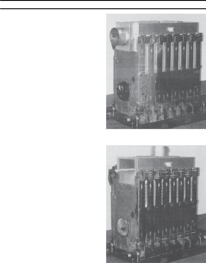
Figure 10: Front and Rear Section Channel Block Positions (Hydraulic Draw-Up)
e. Draw-Up Sections
Use hydraulic rams to draw up sections by applying pressure alternately on the draw-up rods. When rams reach stroke limit, release pressure in ram pumps and then move clamps to new position.
f. Continue to draw-up until all sections make contact at the ground joints.
g. After all sections have been drawn up, but before removing the hydraulic rams and draw-up rods,
the 9¾” long tie rods must be installed.
18
Figure 11: Center Section Channel Block Position
(Partial Block Draw-Up)
The large draw-up rod lugs with dual holes cast in the four (4) corners of each casting. Starting with the upper holes in the back section, install four (4) 5/8” x 9¾” long tie rods along with washers and nuts. Continue installing the tie rods alternating from the upper to lower set
of holes in draw-up lugs until front section is secured. Be certain that all sections are drawn up iron to iron at all three nipple ports.
h.Excess length of draw-up rods must not extend beyond front and rear section to ensure proper fit of jacket, adjust accordingly. Tighten all tie rod nuts until finger tight. Then tighten them an additional ½ turn with a wrench.
C.HYDROSTATIC TEST — After the boiler sections have been assembled, it is essential that the boiler be hydrostatically tested before the canopy, flue cover plates, jacket, or piping is installed.
1.Tankless Heater Installation
If boiler is ordered with tankless heaters, install heaters with the gaskets provided. Table IV gives the maximum number of heaters permissible per assembly and the heater ratings.
2.Plug all boiler tappings and fill boiler completely with cold water.
CAUTION
Do not install gauge until after hydrostatic testing the boiler. Gauge failure may result.
3.All completed boilers must satisfactorily pass the prescribed hydrostatic test.
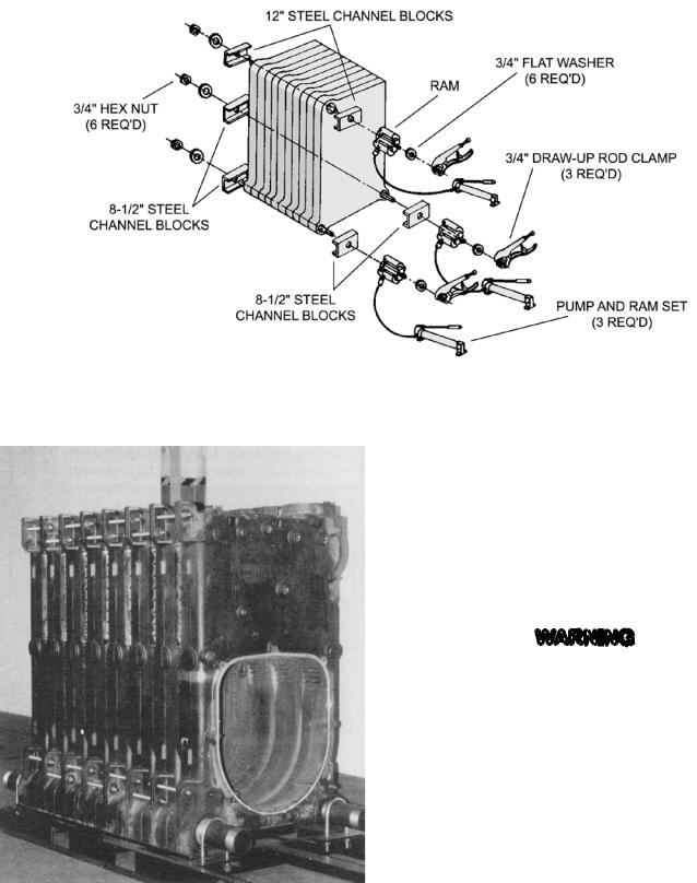
Figure 12: Hydraulic Draw-Up Sections
a. STEAM BOILERS: The assembled boiler must be subjected to a hydrostatic test of 45 psig to 55 psig.
b. HOT WATER BOILERS: The assembled boiler must be subjected to a hydrostatic test of not less than 1½ times the maximum allowable working pressure, as established by the relief valve provided with the boiler. For example, a boiler with a 50 psi relief valve must be subjected to a test pressure of 75 psig to 85 psig.
|
WARNING |
|
|
|
Failure to properly hydrotest all boilers at the |
|
correct pressure may result in section assembly |
|
failure in operation. |
|
4. EXAMINE BOILER CAREFULLY, INSIDE AND |
|
OUTSIDE, to insure against leaks from cocked |
|
nipples or through concealed breakage caused in |
|
shipping and handling. This precaution is for your |
|
protection and will simplify handling of necessary |
|
replacements and adjustment claims. |
|
5. After making certain that there are no leaks, drain |
|
boiler and remove plugs for boiler trim and other |
Figure 13: Boiler Section Assembly |
connections. |
|
19
SECTION III - INSTALLATION INSTRUCTIONS
A.INSTALL CANOPY/FLUE OUTLET ASSEMBLY, Refer to Figures 14, 15 and 16.
1.Open canopy carton.
2.Attach the two (2) canopy brackets to the front end cap of canopy with four (4) #10 x 1/2” sheet metal screws each.
3.Across the top of the front section and along the top ledges running back each side of the sections, place continuous 2” wide strips of cerafelt and overlap joints at front corners. Cerafelt strip should extend 1/4” beyond rear surface of back section. Cut off excess.
4.Place the canopy on the sections.
5.Position rear flange (end with studs) of canopy flush with rear surface of back section.
6.Loosely attach the canopy brackets to the lugs on the front section of the block assembly with 5/16” carriage bolts, flat washers and locknuts.
7.Check to see if rear flange of canopy is still flush with raised flange on back section.
8.Open either the rear flue outlet carton (standard) or top flue outlet carton (optional).
9.Attach the 1/8” x 1” wide self-adhesive fiber gasket to the surface of either the rear flue outlet damper assembly or rear flue outlet cover that mounts against the canopy and back section. Gasket must be centered over all attachment holes. Do not overlap corners, cut butt joints.
10.Attach either the rear flue outlet damper assembly or rear outlet canopy cover to the canopy with the
5/16” flat wasters, lock-washers and brass nuts and tighten securely. Attach the rear flue
outlet damper assembly or cover to the back section with the four (4) 5/16” flat washers and cap screws and tighten securely.
11.Tighten front canopy carriage bolt until canopy is secure.
12.On the longer canopy sizes, Intermediate Mounting Brackets are provided, two (2) are required on sizes V907A thru V909A and four (4) are required on sizes V910A thru V912A. Refer to Figures 17 and 18.
a.Intermediate brackets are shipped flat. Bend side flanges down approximately 90° as shown.
Adjust bends until holes in bracket match hole pattern on canopy.
b.Secure brackets to both sides of canopy with three (3) #10 x ½” sheet metal screws per bracket.
c.Secure canopy left side bracket(s) with appropriate canopy ‘J’ bolt(s). Insert threaded
20 |
end through holes in brackets and hook ‘J’ bolt |
|
Figure 14: Canopy with Rear Flue Outlet Damper Assembly (Shown on optional steel shipping skid)
Figure 15: Canopy with Top Flue Outlet Damper Assembly (Rear Cover Removed)
(Shown on optional steel shipping skid)
 Loading...