


O W N E R ’ S M A N U A L
B T P A I N T B A L L . C O M

CONTENTS |
|
Page |
|
1. Rules for Safe Marker Handling |
|
1 |
|
2. |
Introduction and Specifications |
|
1 |
3. |
Battery Replacement and Life Indicator |
1 |
|
4. |
Compressed Air/Nitrogen Supply |
|
2 |
5. |
Basic Operation |
|
2 |
6. |
Firing the TM-15 |
|
4 |
7. Break Beam Eyes Operation |
|
4 |
|
8. |
Unloading the TM-15 |
|
5 |
9. |
Regulator and Velocity Adjustments |
|
5 |
10. Programming |
|
6 |
|
11. Setting Functions |
|
7 |
|
12. |
Trigger Adjustments |
|
9 |
13. |
General Maintenance |
|
10 |
14. |
Assembly/Disassembly Instructions |
|
11 |
15. |
Storage and Transportation |
|
14 |
16. |
Troubleshooting Guide |
|
14 |
17. Diagrams and Parts List |
|
17 |
|
|
WARRANTY |
(Inside Back Cover) |
|
NEITHER BT PAINTBALL DESIGNS, INC. NOR ANY OF ITS PRODUCTS ARE AFFILIATED WITH TIPPMANN SPORTS, LLC.
For manuals and warranty details, go to: paintballsolutions.com
For manuals in other languages, (where applicable), go to:paintballsolutions.com
©2009 BT Paintball Designs, Inc. The BT Shield, “Battle Tested” and “TM-15” are trademarks of BT Paintball Designs, Inc. All rights reserved.
B T P A I N T B A L L . C O M

1. Rules for Safe Marker Handling
IMPORTANT: Never carry your TM-15 uncased when not on a playing field. The non-playing public and law enforcement personnel may not be able to distinguish between a paintball marker and firearm. For your own safety and to protect the image of the sport, always carry your TM-15 in a suitable marker case or in the box it came in.
•Treat every marker as if it were loaded.
•Never look down the barrel of a paintball marker.
•Keep your finger OFF the trigger until ready to shoot.
•Never point the marker at anything you don’t wish to shoot.
•Keep the marker on “safe” until ready to shoot.
•Keep the barrel blocking device in/on the marker’s barrel when not shooting.
•Always remove paintballs and air source before disassembly.
•After removing air source, point marker in safe direction and discharge until marker is degassed.
•Store the marker unloaded and degassed in a secure place.
•Follow warnings listed on the air source for handling and storage.
•Do not shoot at fragile objects such as windows.
•Every person within range must wear eye, face, and ear protection designed specifically to stop paintballs and meeting ASTM standard F1776.
•Always measure your marker’s velocity before playing paintball and never shoot at velocities in excess of 91.44 meters (300 feet-per-second).
READ OWNERS MANUAL BEFORE USING.
2. Introduction and Specifications
Congratulations on your selection of the TM-15 paintball marker. The TM15 is made to provide you with many years of reliable performance. We are honored that you have chosen the TM-15 as your marker of choice and hope you enjoy using this high quality product.
The patented Valve design, Slip Stream™ Solenoid, Hall Effect Sensor Trigger, and Four Position Selector Switch set new standards for marker tech-
nology. The TM-15 is precision engineered from magnesium alloy, aircraftgrade aluminum, and composite materials. We expect you to play hard and play frequently and the TM-15 was built with this in mind.
The TM-15 operates on low pressure. The main operating pressure is 180–200 PSI. The pressure can be nominally adjusted and monitored visually via the gauge on the bottomline regulator. There is no secondary regulator to worry about.
TM-15 Specifications
Model- TM-15
Barrel14" Ported Barrel
Caliber- .68
ActionSemi Auto, PSP Burst, and NXL Full Auto
Air sourceCompressed Air
BatteryOne 9-Volt (Alkaline Only)
Cycle RateUp to 20 BPS
Shell MaterialMagnesium Alloy
Accuracy Range150ft +
Included with your TM-15
-14" Barrel (.691 bore)
-Allen Wrenches
-Spare Parts Kit
-Barrel Blocking Device
-One 9-Volt Battery
-Manual
-One BT Rip-Clip™Adapter & Adapter Screw Kit, for use with the TM RipClip™ only. (TM Rip-Clip™ not included)
3. Battery Replacement and Life Indicator
The TM-15 requires a single 9-volt alkaline battery as the electronic power source. The use of long life batteries is recommended. The battery is installed by removing the magazine and inserting a 9-Volt battery into the magazine.
B T P A I N T B A L L . C O M |
1 |

To remove the magazine, press in the magazine release button, which is located on the right side of the TM-15. While pressing the release button, pull the magazine down and out of the body and then insert a 9-volt battery following the polarity markings on the side of the magazine. (Fig. 1.1)
|
also has a battery life |
|
When in a firing mode |
|
F3), if the LED flash- |
|
then the battery is |
|
the LED is orange the |
|
fairly depleted and you |
|
change batteries soon, or |
|
is red then the battery |
Fig 1.1 |
replaced immediately. |
|
large for the TM-15 |
|
|
|
please do not force |
them into the magazine.
4. Compressed Air/Nitrogen Supply
The TM-15 is designed to work with compressed air/nitrogen only. Do not use CO2, as it will damage your TM-15.
Consult the Dealer where you purchased your TM-15, or a recognized and competent air smith, for instruction in the safe handling of compressed-air cylinders before purchasing or connecting one to your TM-15.
The TM-15 utilizes a fully functional regulator at the bottom of the grip frame that doubles as an ASA (Air Source Adapter) or Receiver for a standard threaded pre-set output compressed air system. It is strongly recommended that a very high-flow “low-pressure” (350–450 psi) fixed-output system is utilized as an air source for your TM-15. Using a “high-pressure” output compressed air tank is acceptable. If you are using an adjustable out-
put regulator system, the output pressure should be between 400–500 psi.
Before pressurizing your TM-15:
•Check to make sure that you and anyone within range are wearing eye protection designed specifically for paintball.
•Double check that all screws are tightened and no parts are loose before installing your tank.
•Ensure you have a barrel plug, barrel cover, or other specifically designed barrel-blocking device in place.
•Make sure there are no paintballs in the marker.
•The Power should be OFF and the Selector switch should be set to the Safety position.
Air can now be applied; the marker will become pressurized.
Notes:
•Remember compressed air or nitrogen systems can be extremely dangerous if misused or improperly handled. Use only cylinders meeting D.O.T. or regionally defined specifications.
•Never disassemble your tank or tank regulator. Only a qualified and trained technician should perform work on your tank and tank regulator.
•Never add any lubricants or greases into the fill adapter on your tank regulator or into the TM-15 regulator.
5. Basic Operation
Safety and safe marker handling are the most important aspects of paintball sports. Please practice each of the following steps with an unloaded marker before attempting to charge your marker with compressed air and paintballs.
•Do not install compressed air or load paintballs into your TM-15 until you feel completely confident with your ability to handle your TM-15 safely.
2 |
B T P A I N T B A L L . C O M |

•Keep your finger out of the trigger guard and away from the trigger; point the muzzle of the marker in a safe direction at all times. Keep the marker turned OFF when not in use. The TM-15 uses a power switch and a selector switch for its safety devices.
•Always keep your TM-15 pointed in a safe direction. Always use a barrel plug or barrel blocking device. Always use paintball specific eye protection meeting or exceeding ASTM standards in any areas where paintball markers may be discharged.
•Remember that the ultimate safety device is you, the operator.
Feed Elbow Installation |
|
|
Seat the feed elbow onto |
|
|
the narrow section of the |
|
|
top picatinny rail: about 1" |
|
|
forward of the feed hole on |
|
|
the right side of the |
|
|
marker (Fig. 1.2). Then push |
Fig 1.2 |
Fig 1.3 |
and hold in the latch button while sliding the feed
of the marker (Fig. 1.3). Just before the feed elbow covers the feed hole in the right side of the marker, release the latch button and continue sliding the feed elbow until the latch locks into the rail slot. When done correctly, the feed elbow will now be unable to slide forward or backward without holding in the latch button, and the feed hole in the right side shell will not be visible from the sides of the feed elbow.
Barrel Installation
Make sure marker is degassed, hopper removed, no paintballs in the feed elbow or breech, and the TM-15 is turned off.
•While pointing marker in a safe direction, place the threaded end of the barrel into the front opening of the marker body.
•Turn the barrel clockwise until it stops (do not over tighten).
•Install a barrel blocking device. This can be a barrel plug or other such device that prevents the accidental discharge of paintballs.
Switching on your TM-15
Warning: Before switching on your TM-15, make sure it is pointed in a safe direction. Always use a barrel plug or barrel blocking device. Remember that the ultimate safety device is you, the operator.
To switch the TM-15 on, set the selector switch to the (S) safety position. The TM-15 will not turn on unless the selector is in the safety position. Locate the power button on the left side of the marker. Push and hold the power button for 2 seconds and the LED light will turn green and then to
Release the button and the LED will remain red.
will now be on and in the (S) safety position. To make the TM-15 live, selector switch to the F1, F2, or F3 positions. Do not move the selec- a firing position until you are ready to safely use the marker.
OFF your TM-15
Selector Switch to the (S) safety position, push and hold the for 2 seconds, and the LED will turn from red to green.
Release the power button and the TM-15 will switch off.
Selector Switch
The TM-15 comes equipped with a four-position selector switch which comes factory set in the recreational firing mode setting. Move the selector from position (S) safety, to positions (F1, F2, and F3) to change into a firing mode (Fig 1.4).
Selector Positions
Safety ---------------------------------
Semi-Auto ------------------------
PSP Ramping -------------------
NXL Full Auto ------------------
Automatic OFF feature
The TM-15 also has an “Automatic OFF” feature. If you accidentally leave your TM-15 powered up, it will shut itself off after approximately 1 hour of inactivity.
B T P A I N T B A L L . C O M |
3 |
Eye Function
The TM-15 board is pre-programmed to activate the eye system each time the marker is powered up. See Section 7 (Break Beam Eyes Operation) for more details.
Installing a Loader and Paintballs
The TM-15 comes equipped to accept 1.03" (outer dimension) standardgravity feed loaders as well as most agitating and force-feed loaders. Fit the loader directly into the feed elbow. It might be necessary to adjust the feed elbow clamping screw to your loader.
The TM-15 uses .68 caliber, water-soluble paintballs, readily available at paintball pro-shops, commercial playing fields, and many sporting goods stores. The paintballs are fed from the loader through the feed elbow and into the breech of the marker.
Stock Adjustment |
|
|
|
The TM-15 stock can be |
|
|
|
adjusted by depressing the |
|
|
|
stock adjustment lever. |
|
|
|
Adjust the stock’s length by |
|
|
|
pulling or pushing on the |
|
|
|
back of the stock (Fig. 1.5). |
|
|
|
Sight Adjustment |
|
|
|
|
Fig 1.5 |
||
The front and rear sights |
|||
|
|||
can be moved anywhere along |
|
||
folded down or completely |
|
||
remove the sights, loosen the |
|
||
relocate it or remove it. |
|
||
6. Firing the TM-15
Warning: Always keep your TM-15 pointed in a safe direction! Everyone within firing range should always use paintball approved eye and face protection in the presence of live paintball markers.
To turn the TM-15 on, set the selector switch to the (S) safety position, push and hold the power button for 2 seconds, and the LED light will turn green and then red and then release the button. Your TM-15 is now powered on and in the safety position
Firing Your TM-15
•Place the empty loader onto the marker.
•Be sure that it is securely mounted in place.
•Apply the compressed gas, pressurizing the marker.
•Put the paintballs into the loader.
•Remove the barrel plug, sock, or barrel-blocking device. Aim the TM-15 in a safe direction.
Turn the TM-15 on.
Move the selector switch to the desired firing mode. Aim the TM-15 at the target.
Place your finger on the trigger.
Pull the trigger with a smooth squeezing motion.
Note: When the game you are playing is over, remember to place the barrel-blocking device onto your barrel and move the selector to the safety position.
Break Beam Eyes Operation
TM-15 uses a break beam eye system to determine the absence or presence of a ball for the purposes of reduced paint breakage and optimum rates of fire. The TM-15 board is pre-programmed to activate the eye system each time the marker is powered up.
4 |
B T P A I N T B A L L . C O M |
To turn the eyes off, ensure that there are no paintballs in the markers breech or feed elbow and make sure the marker is switched off. While pulling and holding the trigger, turn the marker on. When the selector is switched to a firing mode, a quick double blinking green LED will indicate that the eye system has been deactivated. To turn the eyes back on, simply press the power button one time quickly.
Notes:
•When the eyes are on, a slow consistent single-flashing green LED indicates that no ball is in the breech and a rapid flashing green LED indicates that there is a ball in the breech.
•For optimal performance of the TM-15 eyes, keep the inside of the TM-15 breech clean and clear of broken paint, paint residue, or other debris.
•Although the eyes can be cleaned via cleaning the breech of the TM-15 marker, if the eyes need to be accessed, please follow the steps outlined in the Disassembly/Assembly section of this manual.
8. Unloading the TM-15
Warning: Always keep your TM-15 pointed in a safe direction and always keep your protective eye, face, and ear wear on until marker is completely unloaded and safe.
•Be sure your finger is away from the trigger area.
•Place the barrel plug, sock, or barrel-blocking device into the end of the barrel.
•Move the selector switch to the (S) safety position.
•Turn the TM-15 off by pressing and holding the power button. The LED will change from red to green, once it changes to green, release the button. Observe the light to make sure it is no longer lit.
•Remove your pressurized gas source by slowly and carefully unscrewing it.
•If you are using an electronic loader make sure loader is completely turned off.
•Slightly tilt the marker so that the loader is lower than the body.
•Remove the loader by releasing the clamp and spinning it in a clockwise direction and gently pulling it.
•Read the pressure gauge and make sure the pressure reads 0 psi.
•Do not look down the barrel but look down the feed neck to make sure there are no paintballs in the breech.
•Remove the barrel from the marker.
•Make sure there are no more paintballs remaining in the barrel.
9. Regulator and Velocity Adjustment
The TM-15 utilizes a Bottom-line regulator that doubles as an ASA Adapter/Receiver for a standard threaded pre-set output compressed air systems or remote hose. This unique regulator system channels air through the air transfer tube, eliminating the need for external macro line and fittings. The TM-15 bottom-line regulator controls the amount of air pressure going from your compressed air system into the marker.
The TM-15 regulator should be factory pre-set at about 200 psi, as this is the best operating pressure for proper marker operation. However, if over time you do need to adjust the pressure, use the Regulator Adjuster Screw on the front of your TM-15 bottom-line regulator.
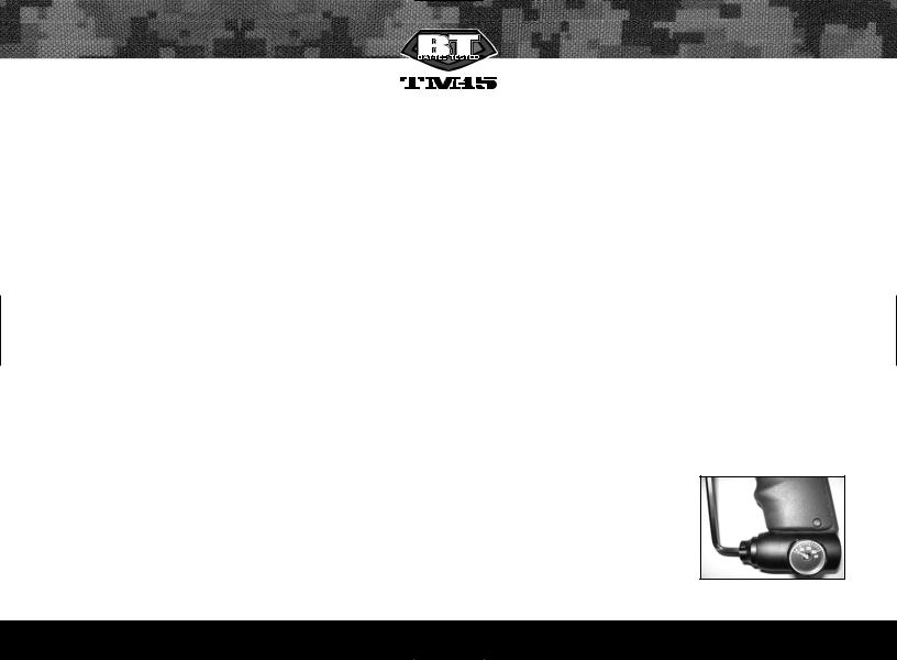
Regulator Adjustment
Note: Do not use this to adjust the velocity of the marker.
If adjustments are needed, use a 3/16" Allen wrench and insert it into the regulator adjustment screw. This is located in the front of the regulator (Fig. 1.6).
To Increase Output PressureTurn the regulator’s adjustment screw clockwise.
To Decrease Output PressureTurn the Fig 1.6 regulator’s adjustment screw counter-clockwise.
B T P A I N T B A L L . C O M |
5 |
Notes:
•Always watch the gauge as you are adjusting the pressure.
•The bottomline regulator should not be disassembled.
•Never set the regulator above 200 psi.
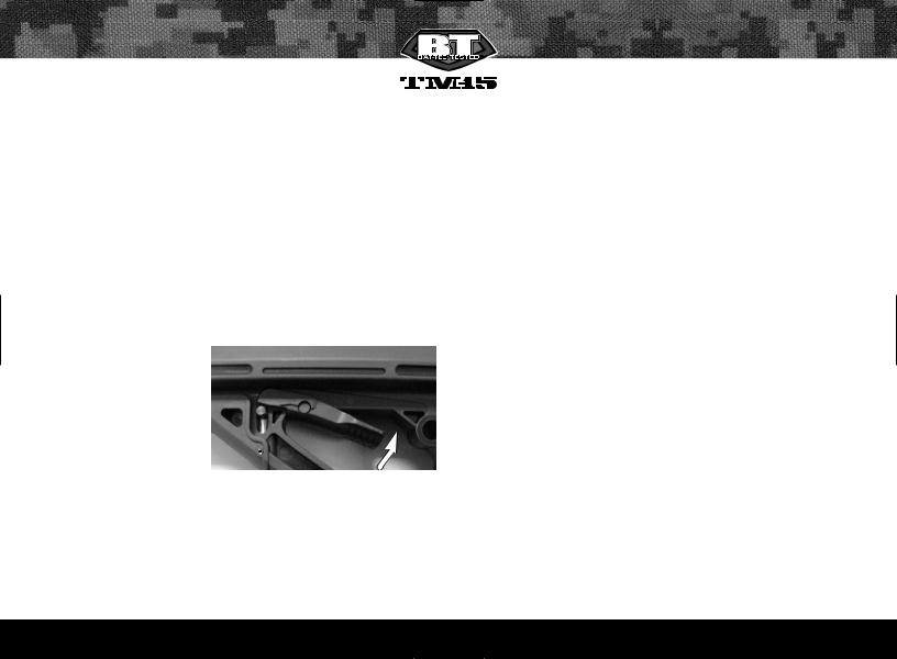
Adjusting VelocityAt the back of the TM-15 internal body is the bolt guide cap. The holes in the bolt guide cap serve as your velocity adjuster. Confirm that the pressure on your TM-15 bottom-line regulator is at 200 PSI.
You can access the velocity adjuster by sliding the velocity adjustment cover forward and inserting a 7/64" Allen wrench into the bolt guide cap thru the bottom of the marker. Then you can increase or decrease the velocity on your TM-15 by tightening or loosening the bolt guide cap, using the included 7/64" inch Allen wrench.
To Increase VelocityUnscrew or loosen the velocity adjustment screw by turning it counter clockwise. Rotate the velocity adjustment screw in small increments, stopping between slight turns to test velocity, until desired velocity is achieved. Do not back the adjuster out too far. Stop if you hear an air leak, and adjust back in a 1/4
turn (Fig. 1.7). A paintball specific radar chronograph should be used to accurately measure your velocity.
To Decrease VelocityTighten or screw-in the velocity adjustment screw by turning it clockwise. Rotate the velocity adjustment screw clockwise in small increments (1/4 turn or less), stopping between slight turns to test velocity, until desired velocity is achieved. A paintball specific radar chronograph should be used to accurately measure your velocity.
Notes:
•This marker was designed with safety and safety standards in mind. If you attempt to shoot paintballs at a higher velocity than established safety standards, the marker may not function properly.
•This marker is not designed to shoot above the safety limits established by Industry Standards, but under certain conditions it may. It is therefore important to check the velocity before using your TM-15.
•The velocity is not adjusted by inserting the Allen wrench into the velocity adjuster and rotating the Allen wrench, but by using the Allen wrench as a handle to rotate the velocity adjuster.
10. Programming
Note: In this section, you will see the phrase "Cycle the Selector Switch". To cycle the selector switch, move the selector switch from the (S) position to the (F3) position and then back to the (S) position.
Tournament Lock On/Off
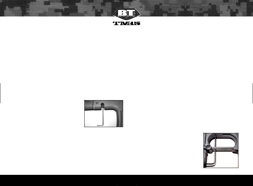
The TM-15 comes with a tournament lock which will lock your marker into the firing mode currently selected. The Tournament lock button is accessed thru a small hole just in front of the trigger. The TM-15 must be turned off to change the tournament lock setting.
Carefully insert the long side of the 3/32" Allen wrench into the hole on the trigger guard and then into the hole on the
body and then gently press the tournament lock button to show the current status of the tourna ment lock (Fig. 1.8).
•If the LED blinks green, the tournament lock is on.
•If the LED blinks red, the tournament lock off.
Fig 1.8
6 |
B T P A I N T B A L L . C O M |
 Loading...