


T6-PAC
T6--PAC, T6--PHP,
T6--NAC, T6--NHP
PREFERREDt SERIES
AC / HP THERMOSTAT
Installation Instructions
A07045 A07044
Programmable Control Non--- Programmable Control
NOTE: Read the e ntire instruction manual before starting the installation.

TABLE OF CONTENTS
PAGE
SAFETY CONSIDERATIONS 2....................................
INTRODUCTION 3..............................................
INSTALLATION CONSIDERATIONS 4..............................
INSTALLATION 7...............................................
SYSTEM START--UP AND CHECKOUT 36..........................
OPERATIONAL INFORMATION 39................................
TROUBLESHOOTING 43.........................................
WIRING DIAGRAMS 45..........................................
THERMOSTAT CONFIGURATION RECORD 54......................
SAFETY CONSIDERATIONS
Read and follow manufacturer instructions carefully. Follow all local electrical
codes during installation. All wiring must conform to local and national electrical
codes. Improper wiring or installation may damage AC/HP Control.
Recognize safety information. This is the safety--alert symbol
this symbol on the equipment and in the instruction manual, be alert to the
potential for personal injury.
Understand the signal words DANGER, WARNING,andCAUTION.These
words are used with the safety--alert symbol. DANGER identifies the most
serious hazards which will result in severe personal injury or death. WARNING
signifies a hazard which could result in personal injury or death. CAUTION is
used to identify unsafe practices which may result in minor personal injury or
product and property damage. NOTE is used to highlight suggestions which will
result in enhanced installation, reliability, or operation.
. When you see
2

INTRODUCTION
Bryant’s 7--day, 5/2--day, 1--day programmable and non--programmable
Preferredt Series Thermostat Control is a wall--mounted, low--voltage control
which combines temperature and humidity control in either a single unit or a
two--piece unit. In two--piece configuration, the relays are located near the
equipment and a two--wire connection is used between the Display Module and
the Equipment Control Module. Single--piece installation requires more wiring
and results in a higher profile. The Preferred Series Thermostat has no need for
batteries to store user--configured settings in memory. During power loss its
internal memory saves settings for unlimited time, and the clock continues to run
for at least 24 hours. An extension of Bryant’s proven line of thermostats; it
provides separate setpoints for heating and cooling in addition to humidification
and dehumidification.
In the control’s programmable configuration, different heating and cooling
setpoints and times are programmable for 4 periods per day or 2 periods per day.
Programming can be done for 7 days per week, 5/2 days per week, or 1 day. The
programmable Thermostat Control can also be user configured as a
non-- programmable Thermostat Control. When operating as non--programmable,
the Preferred Series Thermostat Control will still have both temperature and
humidity control.
The non --programmable Thermostat Control features Touch ’N’ Got settings
for quick and easy temperature change without complicated programming
schedules. The non-- programmable Preferred Series Thermostat Control will still
have both temperature and humidity control. And, its Touch ’N’ Go technology
enables the user to switch between three different user--configurable settings
through intuitive buttons located just below the display.
3

INSTALLATION CONSIDERATIONS
Power
This control is powered by 24VAC only. It requires 24VAC (Rh and/or Rc and C
terminals) of the low--voltage transformer to be connected to it for proper
operation. It will not operate without these 2 connections. Rh and Rc are
connected via PCB breakout jumper. See Fig. 1. For applications using two
24VAC transformers, one in the indoor unit and one in the outdoor unit, connect
the common from each to the C terminal. Connect R from the indoor unit to the
Rh terminal. Connect R from the outdoor unit to the Rc terminal. Then, break
jumper on the circuit board. The W and HUM signals are taken from the Rh
power and the G signal is taken from the Rc power. If Thermidistat Control has
been installed in a two--transformer application that is later changed to a
single--transformer installation, installer must install a field supplied jumper
between Rc and Rh. Depending on the installation, up to 14 wires may be
required. Installation as two--piece unit is recommended. Only 2 wires are
required for connection between Display Module and Equipment Control
Module. These two wires (V+ and Vg) do not provide ordinary 24VAC. They
carry a combination of power and communications data that is unique to these
products.
4

A07052
Fig. 1 -- PCB Breakout Jumper
Models
There are programmable and non-- programmable models for all applications.
They can be configured for AC or HP installations, allowing it to be used in
place of all Bryant thermostats. Programmable thermostats may be configured as
non-- programmable if user desires.
Outdoor Temperature Sensor
The outdoor air temperature sensor is not included with the AC/HP Control. It is
available as an accessory, part number TSTATBBSEN01--B. Optimum
performance is obtained when an outdoor temperature sensor is used with the
AC/HP Control. Plan installation so that 2 wires can be run from Equipment
Control Module to an outdoor location, preferably on the north side of the house
or refer to Installation Instructions included with the outdoor temperature sensor
for simplified connection. Sensor can be mounted to outdoor unit and existing
5

dedicated sensor wires may be used for its connection. Details are provided in
sensor instructions.
Remote Indoor Temperature Sensor
A remote temperature sensor may be used with the programmable heat pump
and programmable air conditioner thermostats where it is desirable to install the
thermostat in a limited access location while measuring the temperature in the
living space. The remote room sensor may be used as a stand alone or average
with local sensor.
Two--Piece Thermostat Configuration
The Preferred Series AC/HP Control can be installed in one of two
configurations. The control may be installed as a single--piece thermostat or it
may be split into two pieces and mounted in separate locations. As a single--piece
unit, all required wiring must be brought to the Equipment Control Module for
connection to the terminal strip. In two--piece configuration, the Display Module
can be mounted in the living space while the Equipment Control Module may be
mounted near the indoor furnace or fan coil. Connection from the display to the
Equipment Control Module requires only two wires. All other control wires are
connected to the Equipment Control Module from the HVAC equipment. This
configuration results in a slimmer display and locates the Equipment Control
Module containing the switching relays away from the main living space where
relay clicking will not be heard.
6

INSTALLATION
Carton contains the following components. See Fig. 2 for programmable models
or Fig. 3 for non--programmable models.
A07756
Fig. 2 -- T6 --PAC / T6--PHP Carton Contents
1. Display Module
2. Stand--off for Equipment Control Module
3. Screws and pig tail
4. Equipment Control Module
7

Fig. 3 -- T6 --NAC / T6--NHP Carton Contents
1. Display Module
2. Stand--off for Equipment Control Module
3. Screws and pig tail
4. Equipment Control Module
AC/HP Control Location
AC/HP Control should be mounted:
S Approximately 5 ft (1.5m) from floor.
S Close to or in a frequently used room, preferably on an inside parti-
tioning wall.
S On a section of wall without pipes or duct work.
8
A07757
AC/HP Control should NOT be mounted:
S Close to a window, on an outside wall, or next to a door leading to the
outside.
S Exposed to direct light or heat from a lamp, sun, fireplace, or other
temperature-- radiating objects which could cause a false reading.
S Close to or in direct airflow from supply registers and return--air regis-
ters.
S In areas with poor air circulation, such as behind a door or in an al-
cove.
Installer should determine whether control will be installed as single--piece or
two--piece. In single--piece configuration, as many as 14 wires may need to run
to wall mounting location for connection to the control. In two-- piece
configuration, the Display Module and Equipment Control Module are
connected by two wires.
Install AC/HP Control
!
ELECTRICAL OPERATION HAZARD
Failure to follow this warning could result in personal injury or
death.
Before installing AC/HP Control, turn off all power to
equipment. There may be more than 1 power disconnect.
WARNING
9

!
CAUTION
UNIT DAMAGE HAZARD
Failure to follow this caution may result in equipment damage
or improper operation.
Improper wiring or installation may damage AC/HP Control.
Check to make sure wiring is correct before proceeding with
installation or turning on power.
1. Turn off all power to equipment.
2. If an existing thermostat is being replaced
a. Remove existing thermostat from wall.
b. Disconnect wires from existing thermostat, 1 at a time.
c. As each wire is disconnected, record wire color and terminal marking.
d. New or additional wire may be needed to accommodate added hu-
midity outputs.
e. Discard or recycle old thermostat.
10

!
CAUTION
ENVIRONMENTAL HAZARD
Failure to follow this caution may result in environmental
damage.
Mercury is a hazardous waste. Federal regulations require that
Mercury be disposed of properly.
Two--Piece Installation
The following steps should be followed for the installation of the two--piece
configuration.
NOTE: The 2-- wire pigtail is not intended to support the weight of the User
Interface. Do not hang the User Interface from the equipment Control Module
screw terminals.
1. Remove mounting plate from back of Display Module by pressing the
two tabs on the bottom edge and pulling away. See Fig. 4 and 5.
11
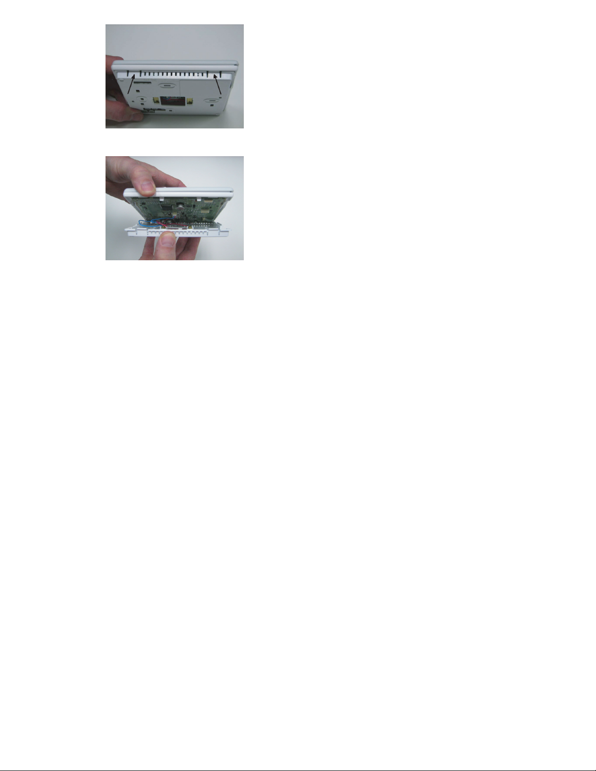
Fig. 4 -- Press Tabs to Remove Backplate
Fig. 5 -- Take Apart
12
A07225
A07226

2. Route wires through large hole in mounting base. Level mounting base
against wall (for aesthetic value only—Display Module need not be leveled for proper operation) and mark wall through 2 mounting holes. See
Fig. 6.
A07165
Fig. 6 -- Backplate Mounting
3. Drill two 3/16--in. mounting holes in wall where marked. Thermostat may
be mounted to a standard junction box, if desired. Hole pattern on thermostat mounting base matches junction box mounting holes.
4. Secure rear plastic mounting base to wall with 2 screws and anchors provided. Additional mounting holes are available for more secure mounting
if needed. Make sure all wires extend through hole in mounting base.
5. Adjust length and routing of each wire to reach proper connector block
and terminal on mounting base with 1/4--in. extra wire.
13
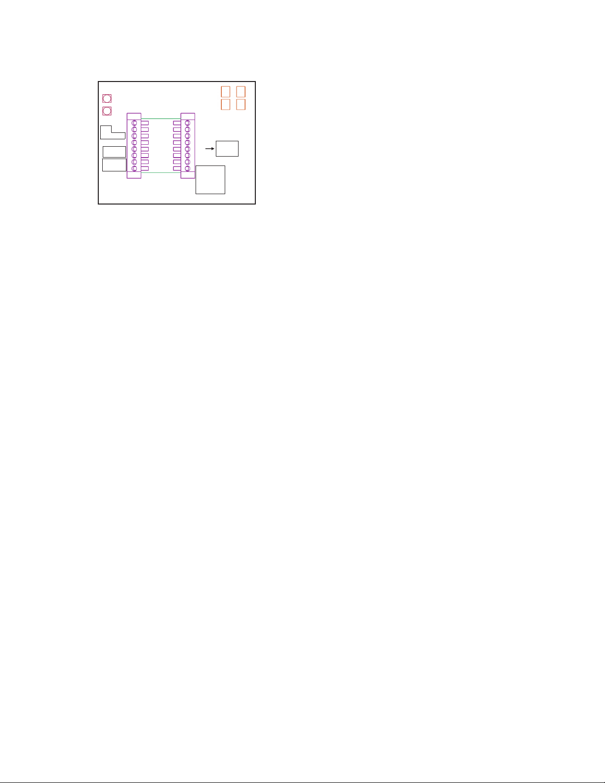
6. Match and connect equipment wires to proper terminals of each connector
block being careful not to over tighten the screws. Correct polarity must
be observed when connecting the two wires from the Equipment Control
Module to the thermostat mounting base. If wires are connected incorrectly, the Display Module will not operate. See Fig. 7, 8 and 9.
OAT /
OAT /
RRS
RRS
return
return
dry
dry
contact
contact
connect
connect
to user
to user
interface
interface
{
{
SRTN
SRTN
OAT
OAT
RRS
RRS
HUM
HUM
D1
D1
D2
D2
V+
V+
Vg
Vg
Control Module Wiring Guide
Control Module Wiring Guide
Rc
Rc
Rh
Rh
W / W1
W / W1
G
G
Y/Y2
Y/Y2
C
C
O/W2/B
O/W2/B
Y1
Y1
Y1 used for
Y1 used for
multi-speed
multi-speed
cooling
cooling
Y1 = stage 1
Y1 = stage 1
Y2 = stage 2
Y2 = stage 2
Relays
Relays
Y used for
Y used for
single stage
single stage
cooling
cooling
Fig. 7 -- Control Module Wiring Guide
S Red is V+
S Black is Vg
A07687
14
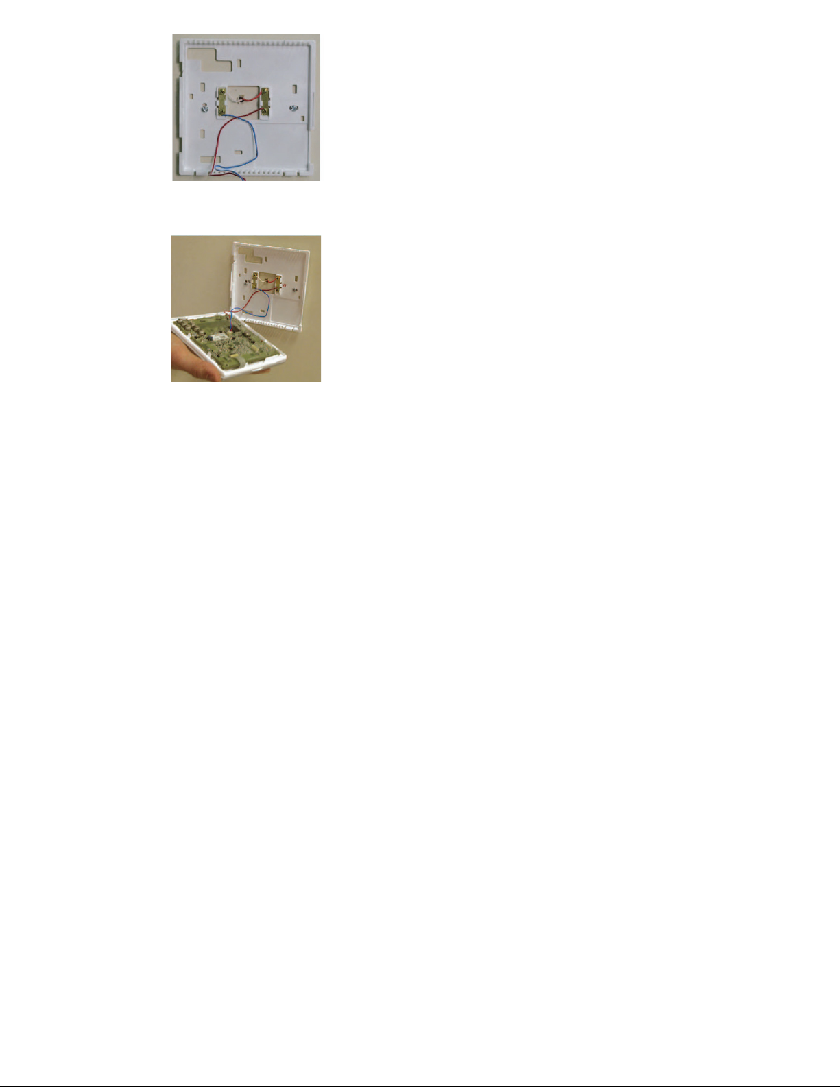
Fig. 8 -- Secure Wires to Terminal Strip
Fig. 9 -- Connect Pigtail Wires to Display Module
15
A07166
A07167
NOTE: The 2-- wire pigtail is not intended to support the weight of the User
Interface. Do not hang the User Interface from the equipment Control Module
screw terminals.
S Red is V+
S Black is Vg
7. Push any excess wire into wall and against mounting base. Seal hole in
wall to prevent air leaks. Leaks can affect operation and cause incorrect
temperature and/or humidity measurement.
8. Make sure to attach 2--wire pigtail to Display Module mounting base. It is
packed loose in the box from the factory. Then attach 2--wire pigtail to the
back of the Display Module via 2 pin, keyed connector.
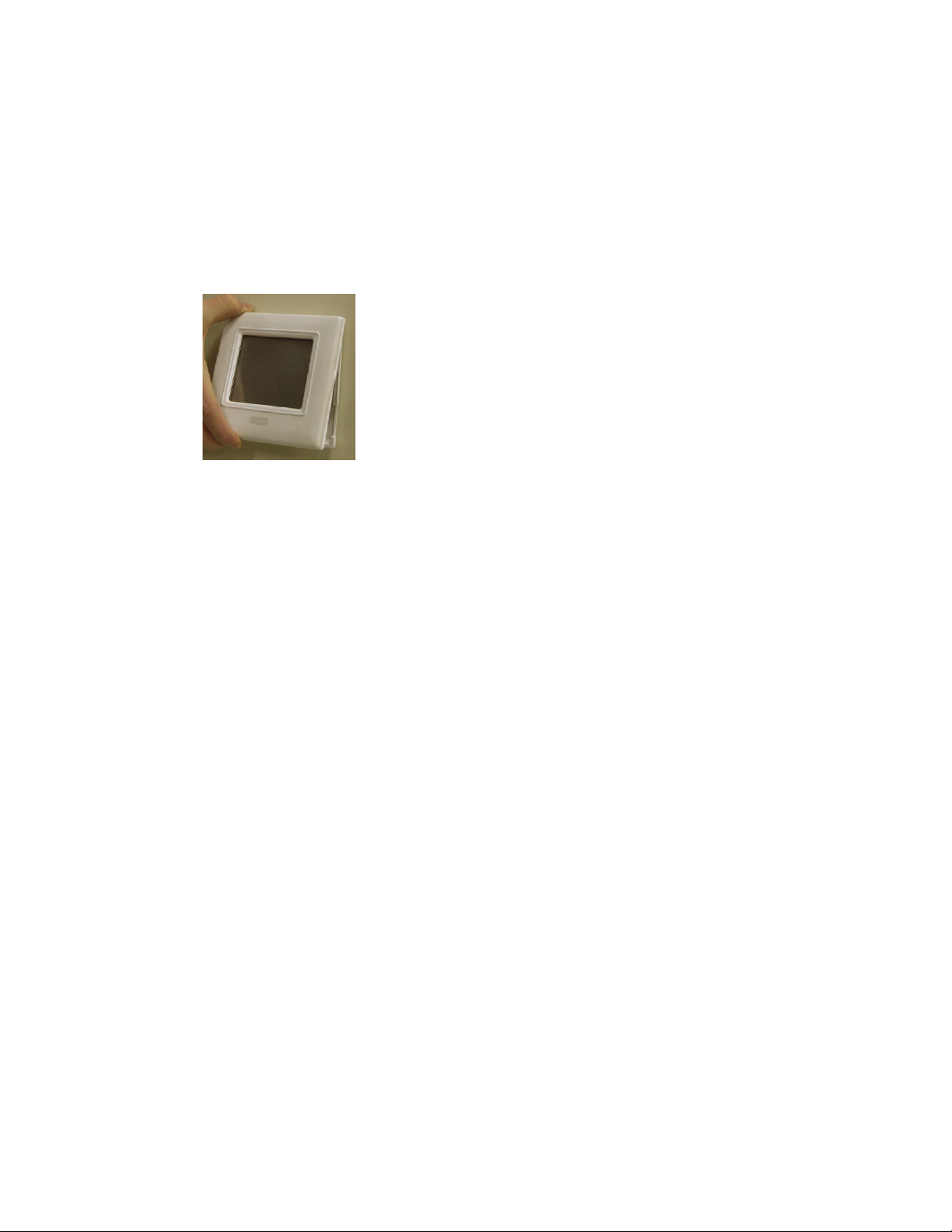
9. Reattach Display Module body to mounting base by first setting on at top
of mounting base and then push bottom corners of Display Module to
snap into place. See Fig. 10.
A07169
Fig. 10 -- Attach Display to Backplate
16
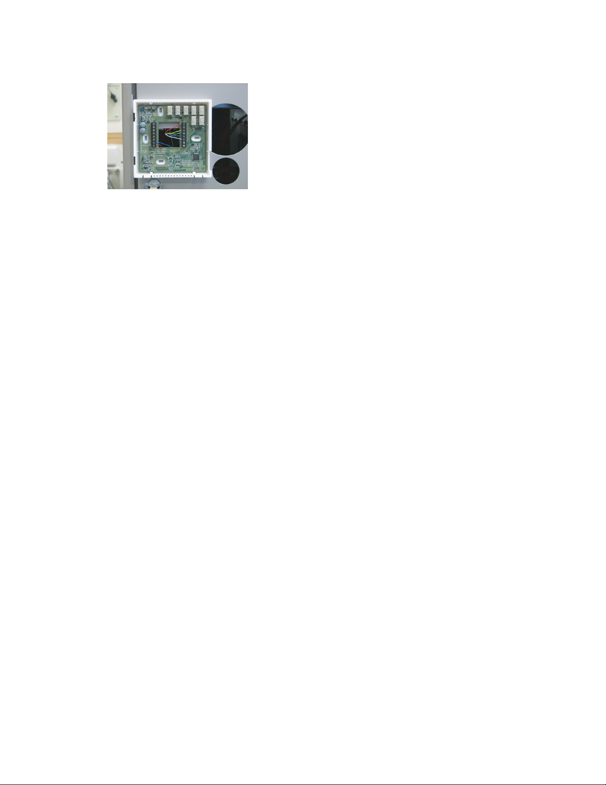
10. Find suitable indoor mounting location for Equipment Control Module,
either near or on equipment. See Fig. 11.
IMPORTANT NOTE: Equipment Control Module should not be mounted
to duct work or below any other controls or equipment (i.e. humidistat,
humidifier, etc.).
A07217
Fig. 11 -- Equipment Control Module on Equipment
11. Route wires through rear of Equipment Control Module using either a
clearance hole or supplied standoff. See Fig. 12.
17
 Loading...