


 Loading...
COMMERCIAL AIR-COOLED |
Models 566D, 566E, 569D, |
|
CONDENSING UNITS WITH |
569F, |
576C |
524A AIR-HANDLING UNITS |
with |
524A |
6 to 20 Tons
569D072-120
576C120
569F120
524A072-300
566D150-240
566E150-240
FEATURES/BENEFITS
These dependable split systems match Bryant’s indoor-air handlers and direct-expansion coils with outdoor condensing units for a wide selection of commercial cooling solutions.
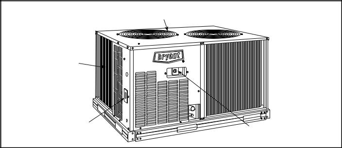
CONSTRUCTED FOR LONG LIFE — The 569D (single circuit, scroll compressor), 576C (single circuit semi-hermetic compressor), 569F/566E (dual circuit, scroll compressor) and 566D (semi-hermetic compressor) models are designed and built to last. The copper tube-aluminum fin outdoor coil construction provides years of trouble-free operation. Where conditions require them, E-coated coils and pre-coated fin coils are also available. Cabinets are constructed of prepainted galvanized steel, delivering unparalleled protection from the environment. Inside and outside surfaces are protected to ensure long life, good looks, and reliable operation. Safety controls are used for enhanced system protection and reliability.
EFFICIENT OPERATION — Building owners will appreciate the high unit EERs (Energy Efficiency Ratios) offered by these condensing units. These units provide greater efficiency than similar units in the marketplace, which translates into yearround operating savings.
CONTROLS FOR PERFORMANCE DEPENDABILITY — The condensing units offer the building owner operating controls and components designed for performance dependability. The highly efficient hermetic and semi-hermetic compressors are engineered for long life and durability. The compressors include overload protection and vibration isolation for enhancement of quiet operation. The high-pressure switch protects the entire refrigeration system from abnormally high operating
pressures. A low-pressure switch protects the system from low-pressure conditions, including loss of charge.
The 569F120 and 566E150-240 units feature 2 scroll compressors and 2 refrigerant circuits that provide continuous air conditioning and design flexibility. These units also include Cycle-LOC™ anti-short-cycling protection which helps to protect the units against compressor failure.
All units include a crankcase heater to eliminate liquid slugging at start-up. Units with semi-hermetic compressors are also equipped with an oil-level sight glass.
Latest safety standards are assured through UL and UL Canada approvals.
INNOVATIVE BRYANT PACKAGED AIR HANDLERS ARE CUSTOM MATCHED TO THE CONDENSING UNITS — The 524A Series has excellent fan performance, efficient directexpansion (DX) coils, a unique combination of indoor-air quality features, and easy installation. Its versatility and state-of- the-art features help to ensure that your split system provides economical performance now and in the future.
Indoor-Air Quality (IAQ) Features — The unique combination of IAQ features in the 524A Series air handlers help to ensure that only clean, fresh, conditioned air is delivered to the occupied space.
Direct-expansion (DX) cooling coils prevent the build-up of humidity in the room, even during part-load conditions. Unit sizes of 10 tons and above feature dual-circuit coils for improved temperature control.
Standard 2-in. disposable filters remove dust and airborne particles from the occupied space for cleaner air.
Form No. PDS 569D.72.2
Thermal insulation contains an EPA-registered immobilized anti-microbial agent to inhibit the growth of bacteria and fungi.
The pitched, non-corroding drain pan can be adjusted for a rightor left-hand connection to suit many applications and provide positive drainage and to prevent standing condensate.
The 524A accessory economizer can provide ventilation air to improve indoor air quality by using demand control ventilation. When used in conjunction with a 2 to 10 VDC adapter on the actuator and a CO2 sensor, the economizer admits fresh outdoor air to replace stale, recirculated indoor air as needed.
Economy — The 524A Series packaged air handlers have low initial costs, and they continue to save money by providing reduced installation expense and energy-efficient performance.
Quick installation is ensured by the multipoise design. Units can be installed in either the horizontal or vertical configuration without modifications. Fan motors and contactors are prewired and thermostatic expansion valves (TXVs) are factory-installed on all 524A direct-expansion models.
High efficiency, precision-balanced fans minimize air turbulence, surging, and unbalanced operation, cutting operation expenses.
The economizer accessory precisely controls the blend of outdoor air and room air to achieve comfort levels. When the outside air enthalpy is suitable, outside air dampers can fully
open to provide “free” cooling without energizing mechanical cooling.
Rugged Dependability — The 524A series units are made to last. The die-formed galvanized steel panels ensure structural integrity under all operating conditions. Galvanized steel fan housings are securely mounted to a die-formed galvanized steel fan deck.
Rugged pillow-block bearings (524A150-300) are securely fastened to the solid steel fan shaft with split collets and clamp locking devices. Smaller unit sizes have spider-type bearings.
Coil Flexibility — Model 524A direct-expansion coils have galvanized steel casings; inlet and outlet connections are on the same end. The coils are designed for use with Refrigerant 22 and have 3/8-in. diameter copper tubes mechanically bonded to aluminum sine-wave fins. The coils include matched, factoryinstalled thermostatic expansion valves (TXVs) with matching distributor nozzles.
Easier Installation and Service — The multipoise design and component layout help you to get the unit installed and running quickly. Units can be converted from horizontal to vertical operation by simply repositioning the unit. Drain pan connections are duplicated on both sides of the unit. The filters, motor, drive, TXVs, and coil connections are all easily accessed by removing a single side panel.
TABLE OF CONTENTS
Page
Features/Benefits . . . . . . . . . . . . . . . . . . . . . . . . . . . . . . . . . . . . . . . . . . . . . 1,2 ARI Capacity Ratings . . . . . . . . . . . . . . . . . . . . . . . . . . . . . . . . . . . . . . . . . . . .3 Options and Accessories . . . . . . . . . . . . . . . . . . . . . . . . . . . . . . . . . . . . . . . 4-6 Selection Procedure . . . . . . . . . . . . . . . . . . . . . . . . . . . . . . . . . . . . . . . . . . . . .7 Controls. . . . . . . . . . . . . . . . . . . . . . . . . . . . . . . . . . . . . . . . . . . . . . . . . . . . . . .8 Typical Wiring Schematics . . . . . . . . . . . . . . . . . . . . . . . . . . . . . . . . . . . . . 9,10
569D072-120, 576C120, 569F120
Model Number Nomenclature . . . . . . . . . . . . . . . . . . . . . . . . . . . . . . . . . . . . .11 Physical Data . . . . . . . . . . . . . . . . . . . . . . . . . . . . . . . . . . . . . . . . . . . . . . . . .12 Dimensions . . . . . . . . . . . . . . . . . . . . . . . . . . . . . . . . . . . . . . . . . . . . . . . . 13,14 Performance Data . . . . . . . . . . . . . . . . . . . . . . . . . . . . . . . . . . . . . . . . . . . 15-25 Electrical Data. . . . . . . . . . . . . . . . . . . . . . . . . . . . . . . . . . . . . . . . . . . . . . . . .26 Application Data . . . . . . . . . . . . . . . . . . . . . . . . . . . . . . . . . . . . . . . . . . . . . . .27 Typical Piping and Wiring . . . . . . . . . . . . . . . . . . . . . . . . . . . . . . . . . . . . . . . .28 Guide Specifications . . . . . . . . . . . . . . . . . . . . . . . . . . . . . . . . . . . . . . . . . 29-32
566D/E150-240
Model Number Nomenclature . . . . . . . . . . . . . . . . . . . . . . . . . . . . . . . . . . . . .33 Physical Data . . . . . . . . . . . . . . . . . . . . . . . . . . . . . . . . . . . . . . . . . . . . . . 34,35 Dimensions . . . . . . . . . . . . . . . . . . . . . . . . . . . . . . . . . . . . . . . . . . . . . . . . 36-38 Performance Data . . . . . . . . . . . . . . . . . . . . . . . . . . . . . . . . . . . . . . . . . . . 39-52 Electrical Data. . . . . . . . . . . . . . . . . . . . . . . . . . . . . . . . . . . . . . . . . . . . . . . . .53 Application Data . . . . . . . . . . . . . . . . . . . . . . . . . . . . . . . . . . . . . . . . . . . . 54-56 Typical Piping and Wiring . . . . . . . . . . . . . . . . . . . . . . . . . . . . . . . . . . . . . 57,58 Guide Specifications . . . . . . . . . . . . . . . . . . . . . . . . . . . . . . . . . . . . . . . . . 59,60
524A072-300
Model Number Nomenclature . . . . . . . . . . . . . . . . . . . . . . . . . . . . . . . . . . . . .61 Physical Data . . . . . . . . . . . . . . . . . . . . . . . . . . . . . . . . . . . . . . . . . . . . . . . . .62 Dimensions . . . . . . . . . . . . . . . . . . . . . . . . . . . . . . . . . . . . . . . . . . . . . . . . 63-65 Performance Data . . . . . . . . . . . . . . . . . . . . . . . . . . . . . . . . . . . . . . . . . . . 66-71 Electrical Data. . . . . . . . . . . . . . . . . . . . . . . . . . . . . . . . . . . . . . . . . . . . . . 72-78 Application Data . . . . . . . . . . . . . . . . . . . . . . . . . . . . . . . . . . . . . . . . . . . . 79-81 Guide Specifications . . . . . . . . . . . . . . . . . . . . . . . . . . . . . . . . . . . . . . . . . 82,83
2

ARI* CAPACITY RATINGS
CONDENSING |
AIR |
|
SYSTEM† |
|
CONDENSING UNIT ONLY** |
|
|||
UNIT |
HANDLER/ |
Net Cap. |
|
EER |
IPLV |
Gross Cap. |
EER |
|
IPLV |
INDOOR COIL |
(Btuh) |
|
(Btuh) |
|
|||||
|
|
|
|||||||
|
524A-B072†† |
69,000 |
|
11.0 |
N/A |
|
|
|
|
569D072 |
524A-C072†† |
72,000 |
|
11.2 |
N/A |
72,000 |
12.4 |
|
N/A |
|
524A-B090 |
71,000 |
|
10.8 |
N/A |
|
|
|
|
|
524A-C090†† |
74,000 |
|
11.0 |
N/A |
|
|
|
|
|
524A-B072 |
87,000 |
|
10.6 |
N/A |
|
|
|
|
569D090 |
524A-C072†† |
91,000 |
|
11.3 |
N/A |
100,000 |
12.7 |
|
N/A |
|
524A-B090 |
90,000 |
|
10.6 |
N/A |
|
|
|
|
|
524A-C090†† |
94,000 |
|
11.2 |
N/A |
|
|
|
|
|
524A-B120 |
118,000 |
|
10.3 |
N/A |
|
|
|
|
569D120 |
524A-C120 |
125,000 |
|
10.4 |
N/A |
133,000 |
12.4 |
|
N/A |
|
524A-B150 |
123,000 |
|
10.4 |
N/A |
|
|
|
|
|
524A-C150 |
130,000 |
|
10.4 |
N/A |
|
|
|
|
|
524A-B120 |
114,000 |
|
10.3 |
13.1 |
|
|
|
|
576C120 |
524A-C120 |
119,000 |
|
10.3 |
13.6 |
124,000 |
12.0 |
|
16.5 |
|
524A-B150 |
118,000 |
|
10.4 |
14.1 |
|
|
|
|
|
524A-C150 |
125,000 |
|
10.3 |
14.5 |
|
|
|
|
|
524A-B120 |
113,000 |
|
10.3 |
11.7 |
|
|
|
|
569F120 |
524A-C120 |
118,000 |
|
10.5 |
12.4 |
123,000 |
12.3 |
|
16.0 |
|
524A-B150 |
118,000 |
|
10.5 |
12.8 |
|
|
|
|
|
524A-C150 |
124,000 |
|
10.9 |
13.2 |
|
|
|
|
|
524A-B150 |
138,000 |
|
10.4 |
12.7 |
|
|
|
|
566D150 |
524A-C150 |
144,000 |
|
10.6 |
13.0 |
150,000 |
12.1 |
|
15.8 |
|
524A-B180 |
144,000 |
|
10.6 |
11.6 |
|
|
|
|
|
524A-C180 |
146,000 |
|
10.8 |
13.1 |
|
|
|
|
|
524A-B120 |
135,000 |
|
9.7 |
9.9 |
|
|
|
|
|
524A-C120 |
143,000 |
|
10.2 |
10.3 |
|
|
|
|
566E150 |
524A-B150 |
145,000 |
|
10.5 |
10.9 |
158,000 |
12.5 |
|
15.1 |
|
524A-C150 |
153,000 |
|
11.1 |
11.5 |
|
|
|
|
|
524A-B180 |
152,000 |
|
10.8 |
11.0 |
|
|
|
|
|
524A-C180 |
161,000 |
|
11.3 |
11.5 |
|
|
|
|
|
524A-B180 |
176,000 |
|
9.8 |
12.3 |
|
|
|
|
566D180 |
524A-C180 |
182,000 |
|
9.7 |
12.1 |
198,000 |
11 |
|
14.9 |
|
524A-B240 |
184,000 |
|
9.8 |
12.2 |
|
|
|
|
|
524A-C240 |
196,000 |
|
10.0 |
12.5 |
|
|
|
|
|
524A-B150 |
176,000 |
|
10.0 |
10.4 |
|
|
|
|
|
524A-C150 |
185,000 |
|
10.3 |
10.8 |
|
|
|
|
566E180 |
524A-B180 |
187,000 |
|
10.2 |
10.5 |
204,000 |
11.9 |
|
13.9 |
|
524A-C180 |
198,000 |
|
10.6 |
10.9 |
|
|
|
|
|
524A-B240 |
194,000 |
|
10.1 |
10.2 |
|
|
|
|
|
524A-C240 |
204,000 |
|
10.4 |
10.4 |
|
|
|
|
566D240 |
524A-C300 |
244,000 |
|
9.5 |
11.8 |
248,000 |
10.5 |
|
13.9 |
566E240 |
524A-C240 |
243,000 |
|
9.6 |
9.8 |
259,000 |
11.2 |
|
13.1 |
524A-B300 |
242,000 |
|
9.6 |
9.9 |
|
||||
|
524A-C300 |
252,000 |
|
9.7 |
9.9 |
|
|
|
|
LEGEND
EER — Energy Efficiency Ratio IPLV — Integrated Part Load Value N/A — Not Applicable
SST — Saturated Suction Temperature
*Air Conditioning and Refrigeration Institute.
†Ratings in accordance with latest ARI Standard revisions.
**Condensing unit only ratings are at 45 F SST and 95 F entering-air temperature. ††ENERGY STAR® compliant combination of condensing unit and air handler/
indoor coil.
SOUND LEVELS, dB — 569D/576C/566D,E
UNIT |
SOUND RATING |
|
|
|
OCTAVE BANDS |
|
|
||||
(60 Hz) dB (A) |
63 |
125 |
250 |
|
500 |
1000 |
2000 |
4000 |
8000 |
||
|
|
|
|||||||||
|
072 |
80.0 |
43.8 |
61.4 |
66.2 |
|
70.8 |
73.8 |
75.2 |
73.0 |
62.7 |
569D |
090 |
84.0 |
58.5 |
67.3 |
71.3 |
|
75.4 |
77.2 |
75.8 |
76.5 |
71.3 |
|
120 |
85.0 |
63.7 |
67.6 |
72.5 |
|
77.0 |
80.4 |
77.5 |
74.7 |
65.9 |
576C |
120 |
83.0 |
52.5 |
66.1 |
75.1 |
|
75.4 |
78.3 |
73.5 |
71.0 |
64.2 |
566D |
150 |
86.2 |
— |
93.0 |
86.0 |
|
83.0 |
80.0 |
78.0 |
73.0 |
71.0 |
180 |
86.2 |
— |
93.0 |
86.0 |
|
83.0 |
80.0 |
78.0 |
73.0 |
71.0 |
|
|
240 |
90.0 |
83.5 |
81.5 |
88.5 |
|
86.5 |
85.5 |
82.5 |
76.5 |
61.5 |
|
150 |
86.9 |
— |
90.9 |
86.1 |
|
83.1 |
84.0 |
73.5 |
71.7 |
66.7 |
566E |
180 |
87.5 |
— |
90.9 |
86.1 |
|
83.4 |
84.5 |
76.6 |
73.2 |
63.5 |
|
240 |
88.0 |
— |
90.9 |
86.1 |
|
83.8 |
84.5 |
79.2 |
74.3 |
65.5 |
ESTIMATED SOUND POWER LEVELS (Lw) — 524A072-300
UNIT |
CFM |
dB(A) |
|
OCTAVE BAND CENTER FREQUENCY |
|
|||||
63 |
125 |
250 |
500 |
1000 |
2000 |
4000 |
||||
|
|
|
||||||||
524A072 |
2,400 |
86.3 |
93.2 |
89.2 |
85.2 |
84.2 |
80.2 |
78.2 |
74.2 |
|
524A090 |
3,000 |
88.3 |
95.3 |
91.3 |
87.3 |
86.3 |
82.3 |
80.3 |
76.3 |
|
524A120 |
4,000 |
91.6 |
98.6 |
94.6 |
90.6 |
89.6 |
85.6 |
83.6 |
79.6 |
|
524A150 |
5,000 |
91.1 |
97.3 |
93.3 |
89.3 |
90.3 |
84.3 |
82.3 |
78.3 |
|
524A180 |
6,000 |
92.7 |
98.9 |
94.9 |
90.9 |
91.9 |
85.9 |
83.9 |
79.9 |
|
524A240 |
8,000 |
96.4 |
102.6 |
98.6 |
94.6 |
95.6 |
89.6 |
87.6 |
83.6 |
|
524A300 |
10,000 |
96.2 |
102.5 |
98.5 |
94.5 |
95.5 |
89.5 |
87.5 |
83.5 |
|
NOTE: Since this data is calculated, these sound power levels may be different than the actual sound power levels. The accoustic center of the unit is located at geometric center of the unit.
3
OPTIONS AND ACCESSORIES
566D, 566E, 569D, 569F, 576C FACTORY-INSTALLED OPTIONS
Dura-Shield Condenser Coils offer several options to match coil protection to site conditions for optimum durability. See table below. Consult your Bryant representative for further information.
E-Coated Aluminum-Fin Coils have a flexible and durable epoxy coating uniformly applied to all coil surfaces. Unlike brittle phenolic dip and bake coatings, E-coating provides superior protection with unmatched flexibility, edge coverage, metal adhesion, thermal performance, and most importantly, corrosion resistance.
E-coated coils provide this protection since all coil surfaces are completely encapsulated from environmental contamination. This coating is especially suitable in industrial environments.
Pre-Coated Fin Coils provide protection in mild coastal environments.
–20 F Low-Ambient Temperature Kit Option (Motormaster®) (566E, 569D, 569F, 576C Only) controls outdoor-fan motor operation to maintain the correct head pressure at low outdoor ambient temperatures.
115-v Convenience Outlet (566E, 569D, 569F, 576C Only) to power up electric drills, lights, and refrigerant recovery machines. This means you are no longer required to run a separate 115-v power supply.
Non-Fused Disconnect Switch (566E, 569D, 569F, 576C Only) to remove power locally at the condensing unit. This switch also includes a power lockout capability to protect the service person. This lockout switch saves the service person time and effort because there is no need to access a distant disconnect switch while servicing the unit.
FIELD-INSTALLED ACCESSORIES
Electric Unloader Package (576C120 Only) includes hardware and solenoid valve to convert a pressure-operated unloader to electric unloading.
–20 F Low-Ambient Temperature Accessory Kit (Motormaster) controls outdoor-fan motor operation to maintain the correct head pressure at low outdoor ambient temperatures.
Condenser Coil Grille Package protects condensing unit coil from impact by large objects and vandalism.
Bryant’s Line of Thermostats provide both programmable and non-programmable capability with the new Debonair® line of commercial programmable thermostats. The Commercial Electronic thermostats provide 7-day programmable capability for economical applications.
Hail Guard Package protects against damage from flying debris and hail.
Gage Panel Package provides a suction and discharge pressure gage for the refrigerant circuit.
CONDENSER COIL OPTIONS
COPPER-TUBE COILS |
|
ENVIRONMENT |
|
|||
WITH DURA-SHIELD |
|
Standard |
|
Mild |
|
Industrial/ |
OPTION |
|
Coastal |
|
Coastal |
||
|
|
|
||||
Al Fins (Standard Coils) |
X |
|
|
|
|
|
Al Fins, E-Coated |
|
|
|
|
X |
|
Al Fins, Pre-Coated |
|
|
X |
|
|
|
LEGEND |
|
|
|
|
|
|
Al — Aluminum |
|
|
|
|
|
|
LOW AMBIENT CONTROL (FACTORY-INSTALLED OR FIELD-INSTALLED)
FACTORY-INSTALLED
DURA-SHIELD
COIL PROTECTION
FACTORY-INSTALLED
CONVENIENCE OUTLET
FACTORY-INSTALLED
DISCONNECT SWITCH
Options and Accessories
4

OPTIONS AND ACCESSORIES (cont)
524A-B, C FACTORY-INSTALLED OPTIONS
Alternate Fan Motors and Drives are available to provide the widest possible range of performance.
High-Capacity 4-Row Coils are available to provide increased latent and sensible capacities (524A-C).
Prepainted Steel Units are available from the factory for applications that require painted units. Units are painted with American Sterling Gray color.
FIELD-INSTALLED ACCESSORIES
Two-Row Hot Water Coils have copper tubes mechanically bonded to aluminum plate fins and non-ferrous headers.
One-Row Steam Coil has copper tubes and aluminum fins. The Inner Distributing Tube (IDT) design provides uniform temperatures across the coil face. The steam coil has a broad operating pressure range; up to 20 psig (138 kPag) at 260 F (127 C). The IDT steam coils are especially suited to applications where sub-freezing air enters the unit.
Electric Resistance Heat Coils have an open-wire design and are mounted in a rigid frame. Safety cutouts for high temperature conditions are standard. Terminal block for single-point power connection is included.
Economizer (Enthalpy Controlled) provides ventilation air and “free” cooling if outside ambient temperature and humidity are suitable.
Discharge Plenum directs the air discharge directly into the occupied space integral horizontal and vertical louvers enable redirection of airflow. Accessory is available unpainted or painted. Field assembly required.
Return-Air Grille provides a protective barrier over the returnair opening and gives a finished appearance to units installed in the occupied space. Accessory is available unpainted or painted.
Subbase provides a stable, raised platform and room for condensate drain trap connection for vertical floor-mounted units. Accessory is available unpainted or painted.
Overhead Suspension Package includes necessary brackets to support units in horizontal ceiling installations.
Bryant’s Line of Thermostats provide both programmable and non-programmable capability. The Commercial Electronic thermostats provide 7-day programmable capability for economical applications.
Condensate Drain Trap includes an overflow shutoff switch that can be wired to turn off the unit if the trap becomes plugged. Kit also includes a wire harness that can be connected to an alarm if desired. The transparent trap is designed for easy service and maintenance.
UV-C Germicidal Lamps kill mold and fungus, which may grow on evaporator coil and condensate pan surfaces. The use of UV-C germicidal lamps eliminates the foul odors that result from this growth of mold and fungus. It also provides a self-cleaning function for the evaporator coil and drain pan.
Commercial Programmable
and Non-Programmable Thermostat
5
OPTIONS AND ACCESSORIES (cont)
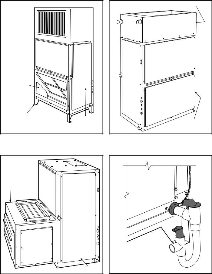
DISCHARGE
PLENUM
RETURN-AIR
GRILLE
SUBBASE
FAN
COIL
UNIT
524A with Discharge Plenum, Return Grille, and Subbase
HOT WATER OR |
STEAM COIL |
FAN COIL |
UNIT |
524A with Hot Water or Steam Coil
ECONOMIZER |
FAN COIL UNIT |
524A with Economizer |
524A with Condensate Trap |
6
SELECTION PROCEDURE
To determine combination ratings for 569D/F, 576C and 566D/E units matched with 524A Series air handlers, follow these steps:
I DETERMINE COOLING LOAD, EVAPORATOR-AIR TEMPERATURE, AND QUANTITY.
Given:
Total Cooling Capacity
Required (TC). . . . . . . . . . . . . . . . . . . . . . 127,000 Btuh Sensible Heat Capacity
Required (SHC) . . . . . . . . . . . . . . . . . . . . . 95,000 Btuh Compressor Type . . . . . . . . . . . . . . . . . . . . . . . . . . .Scroll Temperature Air Entering Condenser (Edb). . . . . . . . 95 F Temperature Air Entering
Evaporator (db/wb). . . . . . . . . . . . . . . .80 F db, 67 F wb Evaporator Air Quantity . . . . . . . . . . . . . . . . . . . 4,000 cfm External Static Pressure . . . . . . . . . . . . . . . . . . 0.4 in. wg Length of Interconnecting
Refrigerant Piping . . . . . . . . . . . . . . . . . . . 25 ft (Linear) Power Supply (V-Ph-Hz) . . . . . . . . . . . . . . . 208/230-3-60
IISELECT CONDENSING UNIT AIR-HANDLER COMBINATION.
For this example, select a 569D120 matched with a 524A-C120 with high-capacity 4-row coil This 569D120/ 524A-C120 condensing unit air-handler combination provides 130,000 Btuh of total cooling capacity and 98,200 Btuh of sensible capacity at the given conditions. If other temperatures or airflow values are required, interpolate the values from the combination ratings.
IIIDETERMINE SIZES OF LIQUID AND SUCTION LINES.
Enter Refrigerant Piping Sizes table. The sizes shown are based on an equivalent length of pipe. This equivalent length is equal to the linear length of pipe indicated at the top of each sizing column, plus a 50% allowance for fitting losses. (For a more accurate determination of actual equivalent length in place of using the estimated 50% value, refer to a standard refrigeration piping practice.) For this example, note in the linear length column that the proper pipe size is 1/2 in. for the liquid line and 13/8 in. for the suction line.
IV DETERMINE FAN RPM AND BHP (BRAKE HORSEPOWER).
At the Air Handler Fan Performance table enter at 524AC120 with high capacity coil at 4000 cfm and move to the External Static Pressure (ESP) column. Note that the conditions require 803 rpm at 1.77 bhp.
VDETERMINE MOTOR AND DRIVE.
Enter the Fan Motor Data tables and find the standard motor for 524A-C120 unit rated at 2.4 Hp. Since the bhp required is 1.77, a standard motor satisfies the requirement and should be used.
Next, find the type of drive that satisfies the 803 rpm requirement in the Drive Data tables. For the 524A-C120 unit, the Standard Drive table on shows an rpm range of 666-863. Since the rpm required is 803, the standard drive satisfies the requirement and should be used. Select the standard motor and standard drive combination (option code GC or ED).
7
CONTROLS
OPERATING SEQUENCES
569D072-120, 576C120 — At start-up, the thermostat calls for cooling. With all safety devices satisfied, the compressor contactor and fan contactor energize, causing the compressor and outdoor-fan motor to operate. Thermostat contacts energize, allowing the field-supplied and field-installed indoorfan contactor to function. A field-supplied and field-installed liquid line valve also opens, allowing the system to function in Cooling mode. As cooling demand is satisfied, the thermostat contacts break, deenergizing the contactor and causing the system to shut off. The liquid line solenoid valve closes, minimizing the potential for refrigerant migration. The compressor does not restart until the thermostat again calls for cooling. The system is protected with a safety circuit so that the system will not start if a fault exists (i.e., high or low pressure fault). To reset the safety circuit, set the thermostat to eliminate the cooling demand, then return to original set point. This should be done only once, and if system shuts down due to the same fault, determine the problem before attempting to restart the system.
566D150-240 — When the first stage of cooling thermostat closes, the timer starts. After approximately 3 seconds, the timer activates the compressor and fan motor no. 1 contactors. When the liquid pressure builds to approximately 257 psig, fan motor no. 2 is energized.
When there is demand for additional cooling capacity, the second stage of the cooling thermostat closes, energizing a field-supplied liquid line solenoid (LLS) valve, which opens. This increases the suction pressure, causing the compressor to operate at higher capacity (compressor loads).
When the fan switch is set at AUTO, the indoor-air fan cycles with the compressor. When the switch is set at CONT, the indoor-air fan runs continuously.
At shutdown, the Time Guard II timer prevents the compressor from restarting for approximately 5 minutes.
In addition, an LLS valve wired in parallel with the compressor contactor coil shuts off the liquid line to prevent refrigerant migration back to the compressor during the off cycle.
569F120 — When the thermostat calls for stage one cooling at start-up, and all safety devices are satisfied, the compressor contactor no. 1 (C1) energizes causing compressor no. 1 and outdoor-fan motor no. 1 to start (the indoor-fan contactor should be wired to start at the same time as the compressor). The liquid line solenoid (LLS) valve will open when compressor no. 1 starts, allowing refrigerant to flow in the system.
When the thermostat calls for stage two cooling, compressor contactor no. 2 (C2) energizes causing compressor no. 2 and outdoor-fan motor no. 2 to start. As the cooling demand decreases, stage two on the thermostat opens, causing compressor no. 2 and outdoor-fan motor no. 2 to shut down. As
the cooling continues to decrease, stage one of the thermostat opens causing compressor no. 1 and outdoor-fan motor no. 1 to shut down. The LLS valve for each compressor will close when the associated compressor stops, minimizing the potential for refrigerant migration during the off cycle.
The indoor-fan motor will stop if the thermostat is set to AUTO and will continue to operate if the thermostat is set to CONT. Each compressor is protected with a Cycle-LOCTM device so that the compressor will not operate if there is a high-pressure fault, low pressure fault, or a compressor is off due to internal line break overcurrent/overtemperature protection. To reset the Cycle-LOC device, set the thermostat higher to remove the cooling demand, then return to the original set point. This should be done only once. If the system shuts down with the same fault, the cause for the fault should be determined and corrected before the a Cycle-LOC device is reset again.
566E150-240 — At start-up, when the thermostat calls for first stage cooling and all safety devices are satisfied, the compressor contactor (C1) energizes causing compressor no. 1 and fan motor no. 1 to start. Fan motor no. 2 will start when the fan cycling pressure switch (FCPS) closes as discharge pressure builds (refer to physical data table for FCPS specifications). With the indoor-fan contactor wired to TB2-4 and TB2-9 contacts on the terminal block, the indoor fan will also start with the compressor. The liquid line solenoid (LLS) valve will open when compressor no. 1 starts, allowing refrigerant to flow in the system.
When the thermostat calls for stage two cooling, compressor contactor no. 2 (C2) energizes causing compressor no. 2 to start. As the cooling demand decreases, stage two on the thermostat opens, causing compressor no. 2 to shut down. As the cooling continues to decrease, stage one of the thermostat opens causing compressor no. 1 and outdoor-fan motor to shut down. The LLS valve for each compressor will close when the associated compressor stops, minimizing the potential for refrigerant migration during the off cycle.
The indoor-fan motor will stop if the thermostat is set to AUTO and will continue to operate if the thermostat is set on CONT. Each compressor is controlled by the thermostat so they will not start until there is a demand from the thermostat. Each compressor is protected with a Cycle-LOC device so that the compressor will not operate if there is a high-pressure fault, low-pressure fault, or compressor is off due to internal line break overcurrent/overtemperature protection. To reset the a Cycle-LOC device, set the thermostat higher to remove the cooling demand, then return to the original set point. This should be done only once. If the system shuts down with the same fault, the cause for the fault should be determined and corrected before the a Cycle-LOC device is reset again.
8
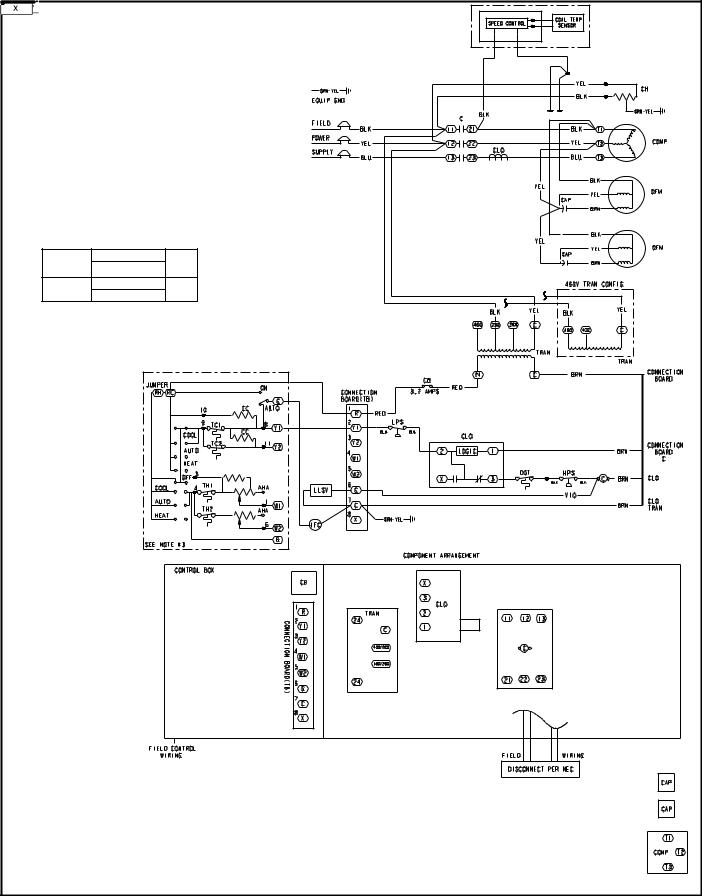
TYPICAL WIRING SCHEMATICS
NOTES:
1. If any of the original wire furnished must be replaced, it must be replaced with type 90° C wire or its equivalent.
2.Thermostat: HH07AT170, 172, 174 & P272-
2783
Subbase: HH93AZ176, 178 & P272-1882, 1883 or HH93AZ177 & 179.
3. Sealed VA for IFC and LLSV is not to exceed 22.
4.Use copper conductors only.
5.TRAN is wired for 230 v unit. If unit is to be run with 200 v power supply, disconnect BLK wire from 230 v tap and connect to 200 v tap.
6.If TRAN is wired for 460-3-60 v and unit is to be run with 400-3-50 v power supply, disconnect BLK wire from 460 v tap and connect to 400 v tap.
7.Three-phase motors are protected under primary single phasing conditions.
VOLTAGE |
CB |
MUST |
|
|
TRIP |
||
RATING |
Mfg. Part No. |
||
AMPS |
|||
24 V |
Potter & Brumfield |
3.2 |
|
W28X-1024-3.2 |
|||
|
|
|
|
|
|
|
|
|
|
LEGEND |
|
|
|
|
|
|
AHA |
— |
Adjustable Heat Anticipator |
LLSV |
— Liquid Line Solenoid Valve |
|
|
|
|
Terminal (Marked) |
|||||
|
|
|
|
|||||||||||
C |
— |
Contactor, Compressor |
LPS |
— |
Low-Pressure Switch |
|
|
|
|
|||||
|
|
|
|
Terminal (Unmarked) |
||||||||||
CAP |
— |
Capacitor |
NEC |
— |
National Electrical Code |
|
|
|
|
|||||
|
|
|
||||||||||||
CB |
— |
Circuit Breaker |
OFM |
— |
Outdoor-Fan Motor |
|
|
|
|
|
Terminal Block |
|||
CC |
— |
Cooling Compensator |
QT |
— |
Quadruple Terminal |
|
|
|
|
|
||||
|
|
|
|
|
Splice |
|||||||||
|
|
|
|
|
||||||||||
CH |
— |
Crankcase Heater |
TB |
— |
Terminal Block |
|
|
|
|
|||||
|
|
|
|
|||||||||||
CLO |
— |
Compressor Lockout |
TC |
— |
Thermostat-Cooling |
|
|
|
|
Factory Wiring |
||||
COMP |
— |
Compressor Motor |
TH |
— |
Thermostat-Heating |
— — |
|
Field Control Wiring |
||||||
DGT |
— |
Discharge Gas Thermostat |
TRAN |
— |
Transformer |
|
||||||||
|
|
|
|
Field Power Wiring |
||||||||||
EQUIP |
— |
Equipment |
|
|
|
|
|
Field Splice |
|
|
|
|
||
|
|
|
|
|
|
|
|
|||||||
GND |
— |
Ground |
|
|
|
|
|
|
|
|
|
Accessory or Optional Wiring |
||
|
|
|
|
|
|
|
|
|
|
|
||||
HPS |
— |
High-Pressure Switch |
|
|
|
|
|
Marked Wire |
|
|
|
|
To Indicate Common Potential |
|
|
|
|
|
|
|
|
|
|
||||||
IFC |
— |
Indoor-Fan Contactor |
|
|
|
|
|
|
|
|
|
|||
|
|
|
|
|
|
|
|
|
|
|
|
|
|
Only, Not Represent Wiring |
|
|
|
|
|
|
|
|
|
|
|
|
|
||
569D090, 208/230-3-360 and 460-3-60 Units
9

TYPICAL WIRING SCHEMATICS (cont)
|
|
LEGEND |
AHA |
— |
Adjustable Heat |
C |
— |
Anticipator |
Contactor, |
||
CAP |
— |
Compressor |
Capacitor |
||
CB |
— |
Circuit Breaker |
CC |
— |
Cooling Compensator |
CH |
— |
Crankcase Heater |
COMP — |
Compressor Motor |
|
COTP |
— |
Compressor Over |
EQUIP — |
Temperature Protection |
|
Equipment |
||
GND |
— |
Ground |
HPS |
— |
High-Pressure Switch |
IFC |
— |
Indoor-Fan Contactor |
LLSV |
— |
Liquid Line Solenoid |
LPS |
— |
Valve |
Low-Pressure Switch |
||
NEC |
— |
National Electrical Code |
OFM |
— |
Outdoor-Fan Motor |
OL |
— |
Overload Relay |
R |
— |
Relay |
TB |
— |
Terminal Block |
TC |
— |
Thermostat-Cooling |
TH |
— |
Thermostat-Heating |
TRAN |
— |
Transformer |
|
|
Field Splice |
|
|
Marked Wire |
|
|
Terminal (Marked) |
|
|
Terminal (Unmarked) |
|
|
Terminal Block |
|
|
Splice |
|
|
Factory Wiring |
— — |
Field Control Wiring |
|
|
|
Field Power Wiring |
|
|
Accessory or |
|
|
Optional Wiring |
|
|
To Indicates Common |
|
|
Potential Only, Not |
|
|
Represent Wiring |
|
|
576C120, 208/230-3-60 and 460-3-60 Units |
10
MODEL NUMBER NOMENCLATURE
569D |
P |
X |
072 |
000 |
– – |
569D — Commercial Air-Cooled Condensing |
|
|
|
|
Factory-Installed Options* |
Unit With Scroll Compressor |
|
|
|
|
|
569F — Dual Circuit Commercial Air-Cooled |
|
|
|
|
|
Condensing Unit With Scroll Compressor |
|
|
|
|
|
Voltage Designation |
|
|
|
|
|
E — 460-3-60 |
|
|
|
|
|
P — 208/230-3-60 |
|
|
|
|
|
T — 575-3-60 |
|
|
|
|
|
Heating |
|
|
|
|
|
X — None |
|
|
|
|
|
Nominal Tons Cooling |
|
|
|
|
|
072 — 6 (569D Only) |
|
|
|
|
|
090 — 7-1/2 (569D Only) |
|
|
|
|
Heating Capacity |
120 — 10 (569D, 569F) |
|
|
|
|
000 — No Heat |
576C |
P |
X |
120 |
000 |
– – |
576C — Commercial Air-Cooled Condensing
Unit With Semi-Hermetic Compressor
Voltage Designation
E — 460-3-60
P — 208/230-3-60
T — 575-3-60
Heating
X — None
*Contact your local representative for more details.
Factory-Installed Options*
Heating Capacity
000 — No Heat
Nominal Tons Cooling
120 — 10
Quality Assurance
Certified to ISO 9001:2000
569F120 576C120,12,012-50TFQ004-569D072
11

569D07250TFQ004-12-12,0 576C120, 569F120
PHYSICAL DATA
569D072-120, 576C120, 569F120 UNITS
UNIT |
|
569D072 |
|
569D090 |
|
|
569D120 |
576C120 |
569F120 |
|||
NOMINAL CAPACITY (tons) |
6 |
|
71/2 |
|
|
|
10 |
10 |
|
10 |
|
|
OPERATING WEIGHT (lb) |
|
|
|
|
|
|
|
|
|
|
|
|
Aluminum Coils (Standard) |
300 |
|
383 |
|
|
|
430 |
575 |
|
488 |
|
|
Copper Coils (Optional) |
352 |
|
484 |
|
|
|
531 |
676 |
|
589 |
|
|
RREFRIGERANT TYPE* |
|
|
|
|
|
|
R-22 |
|
|
|
|
|
Operating Charge, Typical (lb)† |
12 |
|
20 |
|
|
|
22 |
24 |
|
11/Circuit |
||
Shipping Charge (lb) |
2.0 |
|
2.0 |
|
|
|
2.0 |
2.0 |
|
2.0 |
|
|
COMPRESSOR |
|
|
|
|
|
|
|
|
|
|
|
|
Type |
|
|
|
Scroll |
|
|
|
|
Reciprocating |
Scroll |
|
|
Qty...Model |
1...SR_68 |
|
1...SR_94 |
|
|
1...ZR125 |
1...06DH824 |
2...SR_60 |
||||
|
|
|||||||||||
Oil Charge (oz) |
88 |
|
90 |
|
|
|
110 |
128 |
|
72 (ea) |
||
No. Cylinders |
|
|
N/A |
|
|
|
|
6 |
|
N/A |
|
|
Speed (rpm) |
|
3500 |
|
|
|
|
1750 |
|
3500 |
|
||
CONDENSER FAN |
|
|
|
|
|
|
|
|
|
|
|
|
Qty...Rpm |
2...850 |
|
2...1100 |
|
|
2...1100 |
2...1100 |
2...1100 |
||||
Motor HP (rpm) |
1/8 |
|
1/4 |
|
|
|
1/4 |
1/4 |
|
1/4 |
|
|
Diameter |
22 |
|
|
|
22 |
22 |
|
22 |
|
|||
Nominal Airflow (Cfm Total) |
5400 |
|
|
|
6500 |
6500 |
|
6500 |
|
|||
Watts (Total) |
340 |
|
|
|
570 |
570 |
|
570 |
|
|||
CONDENSER COIL (Qty) |
|
2 |
|
|
|
|
|
|
2 |
|
||
Face Area (sq ft total) |
|
29.2 |
|
|
|
|
29.2 |
|
29.2 |
|
||
Rows...Fins/in. |
1...17 |
|
2...17 |
|
|
|
2...17 |
2...17 |
|
2...17 |
|
|
|
|
|
|
|
||||||||
Storage Capacity (lb)** |
17.3 |
|
34.2 |
|
|
|
34.2 |
34.2 |
|
17.1 (ea) |
||
CONTROLS |
|
|
|
|
|
|
|
|
|
|
|
|
Pressurestat Settings (psig) |
|
|
|
|
|
|
|
|
|
|
|
|
High |
Cutout |
|
428 ± 10 |
|
|
|
428 ± 10 |
428 ± 10 |
||||
|
Cut-in |
|
320 ± 20 |
|
|
|
320 ± 20 |
320 ± 20 |
||||
Low |
Cutout |
|
27 ± |
3 |
|
|
|
27 ± |
3 |
27 ± |
3 |
|
|
Cut-in |
|
44 ± |
5 |
|
|
|
44 ± |
5 |
44 ± |
5 |
|
DISCHARGE GAS THERMOSTAT (°F) |
|
2 |
|
|
|
|
|
|
2 |
|
||
Cutout |
|
— |
|
270 ± |
9 |
|
|
— |
— |
|
— |
|
Cut-in |
|
— |
|
190 ± 13 |
|
|
— |
— |
|
— |
|
|
PRESSURE RELIEF |
|
|
|
|
|
|
|
|
|
|
|
|
Location |
|
|
|
|
|
|
|
Suction Line |
|
|
|
|
Temperature (F) |
|
|
|
|
200 |
|
|
|
|
|||
PIPING CONNECTIONS (in. ODM) |
|
|
|
|
|
|
|
|
|
|
|
|
Qty...Suction |
1...11/8 |
|
1...11/8 |
|
|
1...13/8 |
1...13/8 |
2...11/8 |
||||
Qty...Liquid |
1...3/8 |
|
1...3/8 |
|
|
|
1...1/2 |
1...1/2 |
|
2...3/8 |
|
|
*Unit is factory-supplied with holding charge only. |
|
|
NOTE: Unit 576C120 has one step of unloading. Full load is at 100% of |
|||||||||
†Typical operating charge with 25 ft of interconnecting piping. |
|
capacity, and one step of unloading is 67% capacity. Unit 576C120 has |
||||||||||
**Storage capacity of condenser coil with coil 80% full of liquid R-22 at |
|
the following unloader settings: load is 70 ± 1 psig and unload is 60 ± |
||||||||||
95 F. |
|
|
|
2 psig. |
|
|
|
|
|
|
|
|
12

DIMENSIONS
|
|
|
|
|
|
|
|
|
|
|
|
|
|
|
|
|
|
|
|
|
|
|
|
|
|
|
|
|
|
|
|
|
|
|
|
|
|
ALUMINUM COIL |
|
|
|
|
|
|
|
|
|
|
|||||||||||||||
UNIT |
Standard Unit Weight |
|
Corner W |
|
Corner X |
Corner Y |
|
Corner Z |
|
|
|
|
Center of Gravity |
||||||||||||||||||||||||||||||||||||||||||||||||||
|
|
|
|
lb |
|
|
|
|
kg |
|
|
lb |
|
kg |
|
|
|
lb |
|
|
|
kg |
lb |
|
kg |
|
lb |
kg |
|
|
X mm [in.] |
Y mm [in.] |
|||||||||||||||||||||||||||||||
569D072 |
300 |
|
|
136 |
|
|
|
|
|
62 |
|
28 |
|
|
|
|
103 |
|
47 |
62 |
|
28 |
|
72 |
|
33 |
831.9 [32.75] |
641.4 [25.25] |
|||||||||||||||||||||||||||||||||||
569D090 |
383 |
|
|
174 |
|
|
|
|
|
86 |
|
39 |
|
|
|
|
123 |
|
56 |
85 |
|
39 |
|
89 |
|
40 |
822.3 [32.38] |
635.0 [25.00] |
|||||||||||||||||||||||||||||||||||
569D120 |
430 |
|
|
195 |
|
|
|
|
|
84 |
|
38 |
|
|
|
|
166 |
|
75 |
66 |
|
30 |
|
114 |
52 |
812.8 [32.00] |
676.3 [26.63] |
||||||||||||||||||||||||||||||||||||
576C120 |
575 |
|
|
261 |
|
|
|
|
|
55 |
|
25 |
|
|
|
|
265 |
|
120 |
88 |
|
40 |
|
167 |
76 |
927.1 [36.50] |
647.7 [25.50] |
||||||||||||||||||||||||||||||||||||
|
|
|
|
|
|
|
|
|
|
|
|
|
|
|
|
|
|
|
|
|
|
|
|
|
|
|
|
|
|
|
|
|
|
|
|
|
|
|
|
|
|
|
|
|
|
|
|
|
|
|
|
|
|
|
|
|
|
|
|
|
|
|
|
|
|
|
|
|
|
|
|
|
|
|
|
|
|
|
|
|
|
|
|
|
|
|
|
|
|
|
|
|
|
|
|
|
|
|
|
|
|
|
|
|
|
|
|
|
|
|
|
|
|
|
|
|
|
|
|
|
|
|
|
|
|
|
|
|
|
|
|
|
|
|
|
|
|
|
|
|
|
|
|
|
|
|
|
|
|
|
|
|
|
|
|
|
|
|
|
|
|
|
|
|
|
|
|
|
|
|
|
|
|
|
|
|
|
|
|
|
|
|
|
|
|
|
|
|
|
|
|
|
|
|
|
|
|
|
|
|
|
|
|
|
|
|
|
|
|
|
|
|
|
|
|
|
|
|
|
|
|
|
|
|
|
|
|
|
|
|
|
|
|
|
|
|
|
|
|
|
|
|
|
|
|
|
|
|
|
|
|
|
|
|
|
|
|
|
|
|
|
|
|
|
|
|
|
|
|
|
|
|
|
|
|
|
|
|
|
|
|
|
|
|
|
|
|
|
|
|
|
|
|
|
|
|
|
|
|
|
|
|
|
|
|
|
|
|
|
|
|
|
|
|
|
|
|
|
|
|
|
|
|
|
|
|
|
|
|
|
|
|
|
|
|
|
|
|
|
|
|
|
|
|
|
|
|
|
|
|
|
|
|
|
|
|
|
|
|
|
|
|
|
|
|
|
|
|
|
|
|
|
|
|
|
|
|
|
|
|
|
|
|
|
|
|
|
|
|
|
|
|
|
|
|
|
|
|
|
|
|
|
|
|
|
|
|
|
|
|
|
|
|
|
|
|
|
|
|
|
|
|
|
|
|
|
|
|
|
|
|
|
|
|
|
|
|
|
|
|
|
|
|
|
|
|
|
|
|
|
|
|
|
|
|
|
|
|
|
|
|
|
|
|
|
|
|
|
|
|
|
|
|
|
|
|
|
|
|
|
|
|
|
|
|
|
|
|
|
|
|
|
|
|
|
|
|
|
|
|
|
|
|
|
|
|
|
|
|
|
|
|
|
|
|
|
|
|
|
|
|
|
|
|
|
|
|
|
|
|
|
|
|
|
|
|
|
|
|
|
|
|
|
|
|
|
|
|
|
|
|
|
|
|
|
|
|
|
|
|
|
|
|
|
|
|
|
|
|
|
|
|
|
|
|
|
|
|
|
|
|
|
|
|
|
|
|
|
|
|
|
|
|
|
|
|
|
|
|
|
|
|
|
|
|
|
|
|
|
|
|
|
|
|
|
|
|
|
|
|
|
|
|
|
|
|
|
|
|
|
|
|
|
|
|
|
|
|
|
|
|
|
|
|
|
|
|
|
|
|
|
|
|
|
|
|
|
|
|
|
|
|
|
|
|
|
|
|
|
|
|
|
|
|
|
|
|
|
|
|
|
|
|
|
|
|
|
|
|
|
|
|
|
|
|
|
|
|
|
|
|
|
|
|
|
|
|
|
|
|
|
|
|
|
|
|
|
|
|
|
|
|
|
|
|
|
|
|
|
|
|
|
|
|
|
|
|
|
|
|
|
|
|
|
|
|
|
|
|
|
|
|
|
|
|
|
|
|
|
|
|
|
|
|
|
|
|
|
|
|
|
|
|
|
|
|
|
|
|
|
|
|
|
|
|
|
|
|
|
|
|
|
|
|
|
|
|
|
|
|
|
|
|
|
|
|
|
|
|
|
|
|
|
|
|
|
|
|
|
|
|
|
|
|
|
|
|
|
|
|
|
|
|
|
|
|
|
|
|
|
|
|
|
|
|
|
|
|
|
|
|
|
|
|
|
|
|
|
|
|
|
|
|
|
|
|
|
|
|
|
|
|
|
|
|
|
|
|
|
|
|
|
|
|
|
|
|
|
|
|
|
|
|
|
|
|
|
|
|
|
|
|
|
|
|
|
|
|
|
|
|
|
|
|
|
|
|
|
|
|
|
|
|
|
|
|
|
|
|
|
|
|
|
|
|
|
|
|
|
|
|
|
|
|
|
|
|
|
|
|
|
|
|
|
|
|
|
|
|
|
|
|
|
|
|
|
|
|
|
|
|
|
|
|
|
|
|
|
|
|
|
|
|
|
|
|
|
|
|
|
|
|
|
|
|
|
|
|
|
|
|
|
|
|
|
|
|
|
|
|
|
|
|
|
|
|
|
|
|
|
|
|
|
|
|
|
|
|
|
|
|
|
|
|
|
|
|
|
|
|
|
|
|
|
|
|
|
|
|
|
|
|
|
|
|
|
|
|
|
|
|
|
|
|
|
|
|
|
|
|
|
|
|
|
|
|
|
|
|
|
|
|
|
|
|
|
|
|
|
|
|
|
|
|
|
|
|
|
|
|
|
|
|
|
|
|
|
|
|
|
|
|
|
|
|
|
|
|
|
|
|
|
|
|
|
|
|
|
|
|
|
|
|
|
|
|
|
|
|
|
|
|
|
|
|
|
|
|
|
|
|
|
|
|
|
|
|
|
|
|
|
|
|
|
|
|
|
|
|
|
|
|
|
|
|
|
|
|
|
|
|
|
|
|
|
|
|
|
|
|
|
|
|
|
|
|
|
|
|
|
|
|
|
|
|
|
|
|
|
|
|
|
|
|
|
|
|
|
|
|
|
|
|
|
|
|
|
|
|
|
|
|
|
|
|
|
|
|
|
|
|
|
|
|
|
|
|
|
|
|
|
|
|
|
|
|
|
|
|
|
|
|
|
|
|
|
|
|
|
|
|
|
|
|
|
|
|
|
|
|
|
|
|
|
|
|
|
|
|
|
|
|
|
|
|
|
|
|
|
|
|
|
|
|
|
|
|
|
|
|
|
|
|
|
|
|
|
|
|
|
|
|
|
|
|
|
|
|
|
|
|
|
|
|
|
|
|
|
|
|
|
|
|
|
|
|
|
|
|
|
|
|
|
|
|
|
|
|
|
|
|
|
|
|
|
|
|
|
|
|
|
|
|
|
|
|
|
|
|
|
|
|
|
|
|
|
|
|
|
|
|
|
|
|
|
|
|
|
|
|
|
|
|
|
|
|
|
UNIT |
|
ELECTRICAL |
|
|
|
CHARACTERISTICS |
|
||
|
|
|
||
569D072 |
208/230-3-60, 460-3-60, 575-3-60 |
|||
569D090 |
208/230-3-60, 460-3-60, 575-3-60 |
|||
569D120 |
208/230-3-60, 460-3-60, 575-3-60 |
|||
576C120 |
208/230-3-60, 460-3-60, 575-3-60 |
|||
|
|
|
|
|
SERVICE VALVE CONNECTIONS |
|
|||
Unit |
|
Suction |
Liquid |
|
|
mm [in.] |
mm [in.] |
||
|
|
|||
569D072 |
|
28.6 [11/8] |
9.5 |
[3/8] |
569D090 |
|
28.6 [11/8] |
9.5 |
[3/8] |
569D120 |
|
34.9 [13/8] |
12.7 |
[1/2] |
576C120 |
|
34.9 [13/8] |
12.7 |
[1/2] |
569D072-120, 576C120
569F120 576C120,12,012-50TFQ004-569D072
13

569D07250TFQ004-12-12,0 576C120, 569F120
DIMENSIONS (cont)
CORNER “A” |
OUTDOOR COIL |
CORNER “B” |
1162.7
[45.78]
|
|
Y |
|
|
|
|
|
|
|
|
|
|
|
|
|
|
OUTDOOR COIL |
||
ACCESS PANEL |
CORNER “D” |
|
X |
|
CORNER “C” |
|
|||
|
|
|
TOP VIEW |
|
|
|
|
||
O 34.5 [1.36] |
|
ELECTRICAL DISCONNECT |
|
|
|
|
|||
|
LOCATION |
|
|
|
LIQUID |
|
|
||
POWER ENTRY |
|
|
|
|
|
|
|||
|
|
|
|
|
|
|
|||
WITH 50.0/58.0/65.0 K.O. |
|
CONTROL BOX |
|
|
|
CONNECTION |
|||
|
|
ACCESS PANEL |
|
|
|
(SEE CHART |
|
||
|
|
CONVENIENCE |
|
|
OUTDOOR |
FOR SIZE) |
|
||
|
|
|
|
|
|
|
|
||
|
|
OUTLET LOCATION |
|
|
COIL |
SUCTION |
|
||
OUTDOOR |
|
|
|
|
|
CONNECTION |
|||
|
|
|
|
|
(SEE CHART |
|
|||
COIL |
|
|
|
|
|
|
|||
|
582.5 |
|
|
|
FOR SIZE) |
|
|||
|
|
|
|
|
|
||||
|
|
|
|
|
|
|
|
|
|
|
|
[22.93] BOTTOM |
|
|
|
|
|
|
341.5 |
|
|
OF UNIT |
|
|
|
172.9 |
226.9 |
287.8 |
|
|
|
167.5 |
|
|
|
[8.93] |
[11.33] |
[13.45] |
|
|
|
[6.59] |
|
|
|
[6.81] |
|
|
|
|
|
|
|
|
|
|
|
||
111.7 |
|
116.7 |
|
637.9 |
LIQUID CONNECTION |
|
|
|
|
|
644.6 |
[25.11] |
|
|
|
|
|||
FORK TRUCK SLOTS [4.40] |
[4.59] |
|
(SEE CHART FOR SIZE) |
|
|
|
|
||
(3 SIDES ONLY) |
O 22.0 [0.87] FIELD |
[25.38] |
1509.3 |
|
|
|
|
||
|
|
[59.42] |
|
|
|
|
|||
|
ENTRY SERVICE PORT |
|
|
|
|
|
|||
|
|
FRONT VIEW |
|
|
|
|
|||
LEFT SIDE VIEW |
|
|
|
|
|
|
|
||
COMPRESSOR |
OUTDOOR |
|
COIL |
||
ACCESS PANEL |
(in.) (in.)
569F120
REAR VIEW
OUTDOOR |
ACCESS |
872.8 |
|
COIL |
PANEL |
||
[34.36] |
|||
|
|
RIGHT SIDE VIEW
|
|
|
|
|
|
|
ALUMINUM COIL |
|
|
|
||||
|
ELECTRICAL |
Std. Unit |
Corner |
Corner |
Corner |
Corner |
Center of |
|||||||
UNIT |
Wt. |
A |
|
B |
|
C |
|
D |
|
Gravity |
||||
CHARACTERISTICS |
|
|
|
|
||||||||||
|
|
lb |
kg |
lb |
kg |
lb |
kg |
lb |
kg |
lb |
kg |
X |
Y |
|
|
|
mm [in.] |
mm [in.] |
|||||||||||
|
|
|
|
|
|
|
|
|
|
|
|
|||
569F120 |
208/230-3-60, |
|
|
|
|
|
|
|
|
|
|
873.8 |
591.8 |
|
400/460-3-50/60, |
488 |
221 |
102 |
46 |
143 |
65 |
139 |
63 |
104 |
47 |
||||
[34.4] |
[23.3] |
|||||||||||||
|
575-3-60 |
|
|
|
|
|
|
|
|
|
|
|||
|
|
|
|
|
|
|
|
|
|
|
|
|
||
569F120
14

PERFORMANCE DATA
CONDENSING UNIT RATINGS
569D072
|
SST (F) |
|
Air Temperature Entering Condenser (F) |
|
||||
|
|
|
80 |
85 |
95 |
100 |
105 |
115 |
|
|
TC |
53.6 |
52.3 |
49.4 |
48.0 |
46.5 |
43.6 |
25 |
|
kW |
4.24 |
4.49 |
5.02 |
5.31 |
5.60 |
6.24 |
|
|
SDT |
101.0 |
106.0 |
115.0 |
120.0 |
125.0 |
135.0 |
|
|
TC |
59.1 |
57.6 |
54.6 |
53.0 |
51.5 |
48.3 |
30 |
|
kW |
4.33 |
4.57 |
5.10 |
5.39 |
5.69 |
6.33 |
|
|
SDT |
102.0 |
107.0 |
117.0 |
122.0 |
126.0 |
136.0 |
|
|
TC |
64.9 |
63.3 |
60.1 |
58.4 |
56.7 |
53.4 |
35 |
|
kW |
4.42 |
4.67 |
5.20 |
5.49 |
5.79 |
6.43 |
|
|
SDT |
104.0 |
109.0 |
118.0 |
123.0 |
128.0 |
138.0 |
|
|
TC |
71.0 |
69.3 |
65.8 |
64.1 |
62.3 |
58.7 |
40 |
|
kW |
4.53 |
4.77 |
5.31 |
5.60 |
5.90 |
6.55 |
|
|
SDT |
106.0 |
110.0 |
120.0 |
125.0 |
129.0 |
139.0 |
|
|
TC |
77.4 |
75.6 |
71.9 |
70.1 |
68.2 |
64.3 |
45 |
|
kW |
4.65 |
4.89 |
5.43 |
5.72 |
6.02 |
6.68 |
|
|
SDT |
107.0 |
112.0 |
122.0 |
126.0 |
131.0 |
141.0 |
|
|
TC |
84.2 |
82.3 |
78.4 |
76.4 |
74.3 |
70.2 |
50 |
|
kW |
4.78 |
5.03 |
5.56 |
5.86 |
6.16 |
6.81 |
|
|
SDT |
109.0 |
114.0 |
123.0 |
128.0 |
133.0 |
142.0 |
|
|
|
|
|
|
|
||
569D090 |
|
|
|
|
|
|
||
|
SST (F) |
|
Air Temperature Entering Condenser (F) |
|
||||
|
|
|
80 |
85 |
95 |
100 |
105 |
115 |
|
|
TC |
73.9 |
71.7 |
67.0 |
64.6 |
62.1 |
57.0 |
25 |
|
kW |
5.81 |
6.14 |
6.84 |
7.21 |
7.58 |
8.36 |
|
|
SDT |
98.6 |
104.0 |
114.0 |
118.0 |
123.0 |
133.0 |
|
|
TC |
82.0 |
79.7 |
74.9 |
72.4 |
69.9 |
64.7 |
30 |
|
kW |
5.88 |
6.21 |
6.90 |
7.28 |
7.65 |
8.46 |
|
|
SDT |
99.6 |
104.0 |
114.0 |
119.0 |
124.0 |
134.0 |
|
|
TC |
90.4 |
88.0 |
83.0 |
80.4 |
77.8 |
72.4 |
35 |
|
kW |
5.98 |
6.31 |
7.02 |
7.40 |
7.78 |
8.59 |
|
|
SDT |
101.0 |
106.0 |
115.0 |
120.0 |
125.0 |
135.0 |
|
|
TC |
99.2 |
96.7 |
91.4 |
88.7 |
85.9 |
80.3 |
40 |
|
kW |
6.09 |
6.43 |
7.14 |
7.53 |
7.92 |
8.74 |
|
|
SDT |
103.0 |
107.0 |
117.0 |
122.0 |
126.0 |
136.0 |
|
|
TC |
109.0 |
106.0 |
100.0 |
97.4 |
94.5 |
88.6 |
45 |
|
kW |
6.22 |
6.56 |
7.28 |
7.68 |
8.07 |
8.91 |
|
|
SDT |
104.0 |
109.0 |
119.0 |
123.0 |
128.0 |
138.0 |
|
|
TC |
118.0 |
116.0 |
110.0 |
107.0 |
104.0 |
97.2 |
50 |
|
kW |
6.36 |
6.70 |
7.43 |
7.83 |
8.23 |
9.09 |
|
|
SDT |
106.0 |
111.0 |
120.0 |
125.0 |
130.0 |
139.0 |
|
|
|
|
|
|
|
||
569D120 |
|
|
|
|
|
|
||
|
SST (F) |
|
Air Temperature Entering Condenser (F) |
|
||||
|
80 |
85 |
95 |
100 |
105 |
115 |
||
|
|
|
||||||
|
|
TC |
102.0 |
99.3 |
93.8 |
90.9 |
88.1 |
81.9 |
25 |
|
kW |
8.04 |
8.38 |
9.13 |
9.55 |
9.95 |
10.85 |
|
|
SDT |
101.0 |
106.0 |
116.0 |
121.0 |
126.0 |
136.0 |
|
|
TC |
112.0 |
109.0 |
103.0 |
99.8 |
96.7 |
90.3 |
30 |
|
kW |
8.26 |
8.60 |
9.31 |
9.65 |
10.05 |
10.95 |
|
|
SDT |
103.0 |
107.0 |
117.0 |
12.02 |
127.0 |
136.0 |
|
|
TC |
122.0 |
119.0 |
113.0 |
109.0 |
106.0 |
99.0 |
35 |
|
kW |
8.52 |
8.85 |
9.55 |
9.95 |
10.35 |
11.15 |
|
|
SDT |
104.0 |
109.0 |
118.0 |
123.0 |
128.0 |
137.0 |
|
|
TC |
133.0 |
130.0 |
123.0 |
119.0 |
115.0 |
108.0 |
40 |
|
kW |
8.81 |
9.15 |
9.85 |
10.25 |
10.55 |
11.35 |
|
|
SDT |
106.0 |
110.0 |
120.0 |
125.0 |
129.0 |
139.0 |
|
|
TC |
144.0 |
141.0 |
133.0 |
130.0 |
126.0 |
118.0 |
45 |
|
kW |
9.12 |
9.45 |
10.15 |
10.55 |
10.85 |
11.65 |
|
|
SDT |
108.0 |
112.0 |
122.0 |
126.0 |
131.0 |
140.0 |
|
|
TC |
156.0 |
152.0 |
145.0 |
141.0 |
137.0 |
128.0 |
50 |
|
kW |
9.45 |
9.85 |
10.55 |
10.85 |
11.25 |
12.05 |
|
|
SDT |
109.0 |
114.0 |
123.0 |
128.0 |
133.0 |
142.0 |
576C120 |
|
|
|
|
|
|
||
|
SST (F) |
|
Air Temperature Entering Condenser (F) |
|
||||
|
80 |
85 |
95 |
100 |
105 |
115 |
||
|
|
|
||||||
|
|
TC |
89.0 |
85.1 |
77.4 |
73.6 |
69.7 |
62.2 |
25 |
|
kW |
7.52 |
7.79 |
8.29 |
8.49 |
8.70 |
9.02 |
|
|
SDT |
103.0 |
108.0 |
118.0 |
123.0 |
128.0 |
138.0 |
|
|
TC |
101.0 |
96.6 |
88.5 |
84.4 |
80.3 |
72.2 |
30 |
|
kW |
7.76 |
8.07 |
8.64 |
8.89 |
9.14 |
9.55 |
|
|
SDT |
104.0 |
108.0 |
118.0 |
123.0 |
128.0 |
138.0 |
|
|
TC |
113.0 |
109.0 |
100.0 |
95.8 |
91.5 |
83.0 |
35 |
|
kW |
8.01 |
8.36 |
8.99 |
9.28 |
9.55 |
10.05 |
|
|
SDT |
105.0 |
109.0 |
119.0 |
124.0 |
128.0 |
138.0 |
|
|
TC |
125.0 |
121.0 |
112.0 |
107.0 |
103.0 |
94.1 |
40 |
|
kW |
8.29 |
8.66 |
9.35 |
9.65 |
9.95 |
10.55 |
|
|
SDT |
106.0 |
111.0 |
120.0 |
125.0 |
129.0 |
139.0 |
|
|
TC |
138.0 |
133.0 |
124.0 |
119.0 |
115.0 |
106.0 |
45 |
|
kW |
8.57 |
8.97 |
9.75 |
10.05 |
10.50 |
11.05 |
|
|
SDT |
108.0 |
113.0 |
122.0 |
127.0 |
131.0 |
140.0 |
|
|
TC |
152.0 |
147.0 |
137.0 |
132.0 |
127.0 |
117.0 |
50 |
|
kW |
8.85 |
9.28 |
10.15 |
10.45 |
10.90 |
11.55 |
|
|
SDT |
111.0 |
115.0 |
124.0 |
129.0 |
133.0 |
142.0 |
|
|
|
|
|
|
|
||
569F120 |
|
|
|
|
|
|
||
|
SST (F) |
|
Air Temperature Entering Condenser (F) |
|
||||
|
80 |
85 |
95 |
100 |
105 |
115 |
||
|
|
|
||||||
|
|
TC |
90.5 |
87.9 |
82.6 |
79.8 |
76.9 |
71.1 |
25 |
|
kW |
7.75 |
8.17 |
9.05 |
9.52 |
10.00 |
11.00 |
|
|
SDT |
100.0 |
105.0 |
115.0 |
120.0 |
125.0 |
135.0 |
|
|
TC |
100.0 |
97.8 |
92.2 |
89.3 |
86.3 |
80.2 |
30 |
|
kW |
7.79 |
8.21 |
9.09 |
9.57 |
10.10 |
11.10 |
|
|
SDT |
101.0 |
106.0 |
116.0 |
120.0 |
125.0 |
135.0 |
|
|
TC |
111.0 |
108.0 |
102.0 |
99.0 |
96.0 |
89.7 |
35 |
|
kW |
7.89 |
8.30 |
9.18 |
9.66 |
10.10 |
11.20 |
|
|
SDT |
102.0 |
107.0 |
116.0 |
121.0 |
126.0 |
136.0 |
|
|
TC |
122.0 |
119.0 |
112.0 |
109.0 |
106.0 |
99.4 |
40 |
|
kW |
8.01 |
8.42 |
9.31 |
9.79 |
10.30 |
11.30 |
|
|
SDT |
104.0 |
108.0 |
118.0 |
123.0 |
127.0 |
137.0 |
|
|
TC |
133.0 |
130.0 |
123.0 |
120.0 |
116.0 |
109.0 |
45 |
|
kW |
8.15 |
8.57 |
9.46 |
9.95 |
10.40 |
11.50 |
|
|
SDT |
105.0 |
110.0 |
120.0 |
124.0 |
129.0 |
138.0 |
|
|
TC |
145.0 |
141.0 |
134.0 |
131.0 |
127.0 |
120.0 |
50 |
|
kW |
8.30 |
8.72 |
9.63 |
10.10 |
10.60 |
11.70 |
|
|
SDT |
107.0 |
112.0 |
121.0 |
126.0 |
131.0 |
140.0 |
|
|
|
LEGEND |
|
|
|
|
|
kW |
— Compressor Power |
|
|
|
|
|
||
SDT — Saturated Discharge Temperature at Compressor (F) |
|
|
||||||
SST |
— Saturated Suction Temperature (F) |
|
|
|
||||
TC |
— Gross Cooling Capacity (1000 Btuh) |
|
|
|
||||
569F120 576C120,12,012-50TFQ004-569D072
15

569D07250TFQ004-12-12,0 576C120, 569F120
PERFORMANCE DATA (cont)
COMBINATION RATINGS*
UNIT 569D072
569D072/524A-C072 WITH HIGH-CAPACITY 4-ROW COIL
Temp (F) |
|
|
|
|
|
|
|
Evaporator Air — Cfm |
|
|
|
|
|
|
||||||
Air Entering |
|
|
1800 |
|
|
|
|
|
2400 |
|
|
|
|
3000 |
|
|||||
Condenser |
|
|
|
|
|
|
|
Evaporator Air — Ewb (F) |
|
|
|
|
|
|
||||||
|
(Edb) |
|
|
|
|
|
|
|
|
|
|
|
|
|
|
|
|
|
|
|
|
57 |
62 |
|
67 |
|
72 |
57 |
|
62 |
|
67 |
|
72 |
57 |
62 |
|
67 |
72 |
||
|
|
|
|
|
|
|
|
|
||||||||||||
|
|
TC |
66.0 |
68.6 |
|
74.3 |
|
80.7 |
72.0 |
|
72.6 |
|
77.7 |
|
84.1 |
76.2 |
76.2 |
|
79.9 |
86.2 |
80 |
|
SHC |
66.0 |
60.9 |
|
51.0 |
|
40.8 |
72.0 |
|
70.5 |
|
58.6 |
|
45.5 |
76.2 |
76.2 |
|
65.7 |
50.0 |
|
|
kW |
4.45 |
4.49 |
|
4.60 |
|
4.71 |
4.55 |
|
4.57 |
|
4.66 |
|
4.78 |
4.63 |
4.63 |
|
4.70 |
4.82 |
|
|
TC |
65.1 |
67.5 |
|
73.1 |
|
79.3 |
71.0 |
|
71.4 |
|
76.3 |
|
82.6 |
75.0 |
75.1 |
|
78.5 |
84.6 |
85 |
|
SHC |
65.1 |
60.3 |
|
50.5 |
|
40.3 |
71.0 |
|
69.8 |
|
58.1 |
|
45.0 |
75.0 |
75.1 |
|
65.2 |
49.5 |
|
|
kW |
4.72 |
4.76 |
|
4.87 |
|
4.99 |
4.83 |
|
4.84 |
|
4.93 |
|
5.05 |
4.91 |
4.90 |
|
4.97 |
5.09 |
|
|
TC |
63.3 |
65.2 |
|
70.6 |
|
76.7 |
68.9 |
|
69.1 |
|
73.6 |
|
79.7 |
72.8 |
72.8 |
|
75.7 |
81.6 |
95 |
|
SHC |
63.3 |
59.2 |
|
49.4 |
|
39.3 |
68.9 |
|
68.3 |
|
57.0 |
|
44.0 |
72.8 |
72.8 |
|
64.0 |
48.5 |
|
|
kW |
5.26 |
5.30 |
|
5.41 |
|
5.53 |
5.37 |
|
5.38 |
|
5.47 |
|
5.60 |
5.45 |
5.45 |
|
5.51 |
5.64 |
|
|
TC |
62.3 |
64.0 |
|
69.2 |
|
75.2 |
67.7 |
|
67.9 |
|
72.2 |
|
78.2 |
71.5 |
71.5 |
|
74.2 |
80.0 |
100 |
|
SHC |
62.3 |
58.6 |
|
48.9 |
|
38.8 |
67.7 |
|
67.4 |
|
56.5 |
|
43.5 |
71.5 |
71.5 |
|
63.4 |
47.9 |
|
|
kW |
5.57 |
5.61 |
|
5.71 |
|
5.84 |
5.68 |
|
5.68 |
|
5.78 |
|
5.90 |
5.76 |
5.76 |
|
5.82 |
5.95 |
|
|
TC |
61.3 |
62.8 |
|
67.9 |
|
73.8 |
66.6 |
|
66.7 |
|
70.7 |
|
76.6 |
70.3 |
70.3 |
|
72.7 |
78.4 |
105 |
|
SHC |
61.3 |
58.0 |
|
48.3 |
|
38.2 |
66.6 |
|
66.6 |
|
55.9 |
|
42.9 |
70.3 |
70.3 |
|
62.8 |
47.4 |
|
|
kW |
5.88 |
5.91 |
|
6.02 |
|
6.15 |
5.99 |
|
5.99 |
|
6.08 |
|
6.21 |
6.07 |
6.08 |
|
6.12 |
6.26 |
|
|
TC |
59.3 |
60.5 |
|
65.2 |
|
70.9 |
64.4 |
|
64.3 |
|
67.8 |
|
73.5 |
67.9 |
67.9 |
|
69.7 |
75.2 |
115 |
|
SHC |
59.3 |
56.8 |
|
47.2 |
|
37.2 |
64.4 |
|
64.3 |
|
54.8 |
|
41.9 |
67.9 |
67.9 |
|
61.6 |
46.4 |
|
|
kW |
6.51 |
6.53 |
|
6.63 |
|
6.77 |
6.61 |
|
6.61 |
|
6.70 |
|
6.83 |
6.69 |
6.70 |
|
6.74 |
6.88 |
|
|
|
|
|
|
|
|
|
|
|
|
|
|
|||||||
569D072/524A-B072 WITH STANDARD 3-ROW COIL |
|
|
|
|
|
|
|
|
|
|
|
|
|
|||||||
Temp (F) |
|
|
|
|
|
|
|
Evaporator Air — Cfm |
|
|
|
|
|
|
||||||
Air Entering |
|
|
1800 |
|
|
|
|
|
2400 |
|
|
|
|
3000 |
|
|||||
Condenser |
|
|
|
|
|
|
|
Evaporator Air — Ewb (F) |
|
|
|
|
|
|
||||||
|
(Edb) |
|
|
|
|
|
|
|
|
|
|
|
|
|
|
|
|
|
|
|
|
57 |
62 |
|
67 |
|
72 |
57 |
|
62 |
|
67 |
|
72 |
57 |
62 |
|
67 |
72 |
||
|
|
|
|
|
|
|
|
|
||||||||||||
|
|
TC |
63.4 |
66.1 |
|
71.7 |
|
77.8 |
69.0 |
|
69.8 |
|
74.9 |
|
81.1 |
72.9 |
72.9 |
|
76.9 |
83.1 |
80 |
|
SHC |
63.4 |
58.4 |
|
49.0 |
|
39.2 |
69.0 |
|
67.2 |
|
56.0 |
|
43.6 |
72.9 |
72.9 |
|
62.5 |
47.6 |
|
|
kW |
4.40 |
4.45 |
|
4.55 |
|
4.66 |
4.50 |
|
4.52 |
|
4.60 |
|
4.72 |
4.57 |
4.57 |
|
4.64 |
4.76 |
|
|
TC |
62.5 |
65.1 |
|
70.5 |
|
76.6 |
68.0 |
|
68.7 |
|
73.6 |
|
79.7 |
71.9 |
71.9 |
|
75.6 |
81.7 |
85 |
|
SHC |
62.5 |
57.9 |
|
48.5 |
|
38.8 |
68.0 |
|
66.6 |
|
55.5 |
|
43.1 |
71.9 |
71.9 |
|
62.0 |
47.2 |
|
|
kW |
4.67 |
4.72 |
|
4.82 |
|
4.93 |
4.77 |
|
4.79 |
|
4.88 |
|
4.99 |
4.84 |
4.84 |
|
4.91 |
5.03 |
|
|
TC |
60.8 |
62.9 |
|
68.2 |
|
74.1 |
66.1 |
|
66.5 |
|
71.1 |
|
77.0 |
69.7 |
69.8 |
|
73.1 |
78.9 |
95 |
|
SHC |
60.8 |
56.8 |
|
47.5 |
|
37.9 |
66.1 |
|
65.2 |
|
54.6 |
|
42.2 |
69.7 |
69.8 |
|
60.9 |
46.2 |
|
|
kW |
5.22 |
5.26 |
|
5.36 |
|
5.48 |
5.32 |
|
5.33 |
|
5.42 |
|
5.54 |
5.39 |
5.39 |
|
5.46 |
5.58 |
|
|
TC |
59.9 |
61.8 |
|
67.0 |
|
72.8 |
65.1 |
|
65.4 |
|
69.8 |
|
75.6 |
68.6 |
68.6 |
|
71.7 |
77.4 |
100 |
|
SHC |
59.9 |
56.3 |
|
47.0 |
|
37.4 |
65.1 |
|
64.4 |
|
54.0 |
|
41.7 |
68.6 |
68.6 |
|
60.4 |
45.7 |
|
|
kW |
5.53 |
5.56 |
|
5.67 |
|
5.79 |
5.63 |
|
5.63 |
|
5.73 |
|
5.85 |
5.70 |
5.70 |
|
5.76 |
5.89 |
|
|
TC |
59.0 |
60.7 |
|
65.7 |
|
71.4 |
64.0 |
|
64.2 |
|
68.5 |
|
74.1 |
67.5 |
67.5 |
|
70.3 |
75.9 |
105 |
|
SHC |
59.0 |
55.7 |
|
46.5 |
|
36.9 |
64.0 |
|
63.7 |
|
53.5 |
|
41.2 |
67.5 |
67.5 |
|
59.8 |
45.2 |
|
|
kW |
5.84 |
5.87 |
|
5.98 |
|
6.10 |
5.94 |
|
5.94 |
|
6.03 |
|
6.16 |
6.01 |
6.01 |
|
6.07 |
6.20 |
|
|
TC |
57.1 |
58.4 |
|
63.3 |
|
68.7 |
61.9 |
|
61.9 |
|
65.8 |
|
71.3 |
65.2 |
65.2 |
|
67.4 |
72.9 |
115 |
|
SHC |
57.1 |
54.6 |
|
45.5 |
|
35.9 |
61.9 |
|
61.9 |
|
52.4 |
|
40.2 |
65.2 |
65.2 |
|
58.7 |
44.2 |
|
|
kW |
6.46 |
6.48 |
|
6.59 |
|
6.72 |
6.57 |
|
6.56 |
|
6.65 |
|
6.78 |
6.64 |
6.63 |
|
6.68 |
6.82 |
LEGEND
Edb — Entering Dry Bulb
Ewb — Entering Wet Bulb
kW — Compressor Motor Power Input
SHC — Sensible Heat Capacity (1000 Btuh) Gross TC — Total Capacity (1000 Btuh) Gross
*Combinations on this page are ENERGY STAR® compliant.
16
PERFORMANCE DATA (cont)
COMBINATION RATINGS (cont)
UNIT 569D072 (cont)
569D072/524A-C090 WITH HIGH-CAPACITY 4-ROW COIL*
Temp (F) |
|
|
|
|
|
|
|
Evaporator Air — Cfm |
|
|
|
|
|
|
||||||
Air Entering |
|
|
2400 |
|
|
|
|
|
3000 |
|
|
|
|
3750 |
|
|||||
Condenser |
|
|
|
|
|
|
|
Evaporator Air — Ewb (F) |
|
|
|
|
|
|
||||||
|
(Edb) |
|
|
|
|
|
|
|
|
|
|
|
|
|
|
|
|
|
|
|
|
57 |
62 |
|
67 |
|
72 |
57 |
|
62 |
|
67 |
|
72 |
57 |
62 |
|
67 |
72 |
||
|
|
|
|
|
|
|
|
|
||||||||||||
|
|
TC |
71.9 |
72.9 |
|
78.3 |
|
84.8 |
77.7 |
|
77.7 |
|
81.3 |
|
87.6 |
81.6 |
81.6 |
|
83.4 |
89.4 |
80 |
|
SHC |
71.9 |
69.5 |
|
57.7 |
|
45.1 |
77.7 |
|
77.7 |
|
67.0 |
|
50.9 |
81.6 |
81.6 |
|
75.2 |
56.4 |
|
|
kW |
4.55 |
4.57 |
|
4.67 |
|
4.79 |
4.66 |
|
4.66 |
|
4.73 |
|
4.85 |
4.73 |
4.73 |
|
4.77 |
4.89 |
|
|
TC |
70.9 |
71.7 |
|
76.9 |
|
83.3 |
76.5 |
|
76.5 |
|
79.8 |
|
86.1 |
80.3 |
80.3 |
|
81.9 |
87.8 |
85 |
|
SHC |
70.9 |
68.8 |
|
57.2 |
|
44.6 |
76.5 |
|
76.5 |
|
66.4 |
|
50.3 |
80.3 |
80.3 |
|
74.6 |
55.9 |
|
|
kW |
4.83 |
4.84 |
|
4.94 |
|
5.07 |
4.93 |
|
4.93 |
|
5.00 |
|
5.12 |
5.01 |
5.01 |
|
5.04 |
5.16 |
|
|
TC |
68.8 |
69.3 |
|
74.2 |
|
80.4 |
74.1 |
|
74.1 |
|
76.9 |
|
82.9 |
77.7 |
77.8 |
|
79.0 |
84.5 |
95 |
|
SHC |
68.8 |
67.5 |
|
56.1 |
|
43.5 |
74.1 |
|
74.1 |
|
65.2 |
|
49.3 |
77.7 |
77.8 |
|
73.3 |
54.8 |
|
|
kW |
5.37 |
5.38 |
|
5.48 |
|
5.61 |
5.48 |
|
5.48 |
|
5.54 |
|
5.66 |
5.55 |
5.56 |
|
5.58 |
5.70 |
|
|
TC |
67.7 |
68.0 |
|
72.8 |
|
78.8 |
72.8 |
|
72.9 |
|
75.4 |
|
81.3 |
76.4 |
76.4 |
|
77.4 |
82.8 |
100 |
|
SHC |
67.7 |
66.8 |
|
55.5 |
|
43.0 |
72.8 |
|
72.9 |
|
64.6 |
|
48.8 |
76.4 |
76.4 |
|
72.5 |
54.3 |
|
|
kW |
5.68 |
5.69 |
|
5.79 |
|
5.92 |
5.79 |
|
5.79 |
|
5.85 |
|
5.97 |
5.87 |
5.87 |
|
5.89 |
6.01 |
|
|
TC |
66.5 |
66.8 |
|
71.3 |
|
77.3 |
71.6 |
|
71.6 |
|
73.9 |
|
79.6 |
75.0 |
75.0 |
|
75.9 |
81.1 |
105 |
|
SHC |
66.5 |
66.0 |
|
54.9 |
|
42.5 |
71.6 |
|
71.6 |
|
64.0 |
|
48.2 |
75.0 |
75.0 |
|
71.8 |
53.7 |
|
|
kW |
5.99 |
6.00 |
|
6.09 |
|
6.23 |
6.10 |
|
6.10 |
|
6.15 |
|
6.28 |
6.18 |
6.18 |
|
6.20 |
6.32 |
|
|
TC |
64.3 |
64.3 |
|
68.4 |
|
74.2 |
69.0 |
|
69.1 |
|
70.8 |
|
76.2 |
72.3 |
72.3 |
|
72.7 |
77.7 |
115 |
|
SHC |
64.3 |
64.3 |
|
53.8 |
|
41.4 |
69.0 |
|
69.1 |
|
62.8 |
|
47.1 |
72.3 |
72.3 |
|
70.3 |
52.6 |
|
|
kW |
6.61 |
6.61 |
|
6.71 |
|
6.85 |
6.73 |
|
6.73 |
|
6.77 |
|
6.90 |
6.81 |
6.8 |
|
6.81 |
6.94 |
|
|
|
|
|
|
|
|
|
|
|
|
|
|
|||||||
569D072/524A-B090 WITH STANDARD 3-ROW COIL |
|
|
|
|
|
|
|
|
|
|
|
|
|
|||||||
Temp (F) |
|
|
|
|
|
|
|
Evaporator Air — Cfm |
|
|
|
|
|
|
||||||
Air Entering |
|
|
2400 |
|
|
|
|
|
3000 |
|
|
|
|
3750 |
|
|||||
Condenser |
|
|
|
|
|
|
|
Evaporator Air — Ewb (F) |
|
|
|
|
|
|
||||||
|
(Edb) |
|
|
|
|
|
|
|
|
|
|
|
|
|
|
|
|
|
|
|
|
57 |
62 |
|
67 |
|
72 |
57 |
|
62 |
|
67 |
|
72 |
57 |
62 |
|
67 |
72 |
||
|
|
|
|
|
|
|
|
|
||||||||||||
|
|
TC |
68.4 |
69.5 |
|
74.8 |
|
81.0 |
73.6 |
|
73.6 |
|
77.6 |
|
83.8 |
77.3 |
77.3 |
|
79.5 |
85.5 |
80 |
|
SHC |
68.4 |
65.8 |
|
54.8 |
|
42.9 |
73.6 |
|
73.6 |
|
63.1 |
|
48.1 |
77.3 |
77.3 |
|
70.4 |
52.9 |
|
|
kW |
4.49 |
4.51 |
|
4.61 |
|
4.72 |
4.58 |
|
4.58 |
|
4.65 |
|
4.77 |
4.65 |
4.65 |
|
4.69 |
4.81 |
|
|
TC |
67.4 |
68.4 |
|
73.6 |
|
79.7 |
72.6 |
|
72.6 |
|
76.3 |
|
82.4 |
76.1 |
76.1 |
|
78.2 |
84.0 |
85 |
|
SHC |
67.4 |
65.2 |
|
54.3 |
|
42.4 |
72.6 |
|
72.6 |
|
62.6 |
|
47.6 |
76.1 |
76.1 |
|
69.8 |
52.4 |
|
|
kW |
4.76 |
4.78 |
|
4.88 |
|
5.00 |
4.86 |
|
4.86 |
|
4.93 |
|
5.05 |
4.92 |
4.92 |
|
4.96 |
5.08 |
|
|
TC |
65.5 |
66.2 |
|
71.1 |
|
77.1 |
70.4 |
|
70.5 |
|
73.7 |
|
79.5 |
73.8 |
73.8 |
|
75.5 |
81.1 |
95 |
|
SHC |
65.5 |
64.0 |
|
53.3 |
|
41.5 |
70.4 |
|
70.5 |
|
61.5 |
|
46.6 |
73.8 |
73.8 |
|
68.7 |
51.4 |
|
|
kW |
5.31 |
5.32 |
|
5.42 |
|
5.54 |
5.40 |
|
5.40 |
|
5.47 |
|
5.59 |
5.47 |
5.47 |
|
5.51 |
5.62 |
|
|
TC |
64.5 |
65.1 |
|
69.7 |
|
75.6 |
69.3 |
|
69.3 |
|
72.3 |
|
78.0 |
72.6 |
72.6 |
|
74.0 |
79.5 |
100 |
|
SHC |
64.5 |
63.3 |
|
52.8 |
|
41.0 |
69.3 |
|
69.3 |
|
60.9 |
|
46.1 |
72.6 |
72.6 |
|
68.0 |
50.9 |
|
|
kW |
5.62 |
5.63 |
|
5.72 |
|
5.85 |
5.71 |
|
5.72 |
|
5.78 |
|
5.90 |
5.78 |
5.78 |
|
5.82 |
5.93 |
|
|
TC |
63.4 |
63.9 |
|
68.4 |
|
74.1 |
68.1 |
|
68.1 |
|
70.9 |
|
76.5 |
71.4 |
71.4 |
|
72.6 |
77.9 |
105 |
|
SHC |
63.4 |
62.5 |
|
52.2 |
|
40.5 |
68.1 |
|
68.1 |
|
60.4 |
|
45.6 |
71.4 |
71.4 |
|
67.3 |
50.4 |
|
|
kW |
5.93 |
5.94 |
|
6.03 |
|
6.16 |
6.03 |
|
6.03 |
|
6.08 |
|
6.21 |
6.10 |
6.10 |
|
6.12 |
6.24 |
|
|
TC |
61.4 |
61.6 |
|
65.8 |
|
71.2 |
65.9 |
|
65.8 |
|
68.0 |
|
73.4 |
68.9 |
68.9 |
|
69.7 |
74.8 |
115 |
|
SHC |
61.4 |
61.1 |
|
51.2 |
|
39.4 |
65.9 |
|
65.8 |
|
59.2 |
|
44.6 |
68.9 |
68.9 |
|
66.0 |
49.4 |
|
|
kW |
6.55 |
6.55 |
|
6.64 |
|
6.78 |
6.65 |
|
6.65 |
|
6.70 |
|
6.83 |
6.72 |
6.73 |
|
6.74 |
6.86 |
LEGEND
Edb — Entering Dry Bulb
Ewb — Entering Wet Bulb
kW — Compressor Motor Power Input
SHC — Sensible Heat Capacity (1000 Btuh) Gross TC — Total Capacity (1000 Btuh) Gross
*This combination is ENERGY STAR® compliant.
569F120 576C120,12,012-50TFQ004-569D072
17
569D07250TFQ004-12-12,0 576C120, 569F120
PERFORMANCE DATA (cont)
COMBINATION RATINGS (cont)
UNIT 569D090
569D090/524A-C072 WITH HIGH-CAPACITY 4-ROW COIL*
Temp (F) |
|
|
|
|
|
|
Evaporator Air — Cfm |
|
|
|
|
|
|
||||||
Air Entering |
|
|
1800 |
|
|
|
|
2400 |
|
|
|
|
3000 |
|
|||||
Condenser |
|
|
|
|
|
|
Evaporator Air — Ewb (F) |
|
|
|
|
|
|||||||
|
(Edb) |
|
|
|
|
|
|
|
|
|
|
|
|
|
|
|
|
|
|
|
57 |
62 |
|
67 |
72 |
57 |
|
62 |
|
67 |
|
72 |
57 |
62 |
|
67 |
72 |
||
|
|
|
|
|
|
|
|
||||||||||||
|
|
TC |
78.9 |
85.1 |
|
92.8 |
101.0 |
87.0 |
|
90.7 |
|
98.3 |
|
106.0 |
93.0 |
94.7 |
|
102.0 |
110.0 |
80 |
|
SHC |
77.9 |
69.0 |
|
59.0 |
48.7 |
87.0 |
|
79.9 |
|
66.9 |
|
53.6 |
93.0 |
89.3 |
|
74.2 |
58.0 |
|
|
kW |
5.75 |
5.78 |
|
5.85 |
5.94 |
5.79 |
|
5.83 |
|
5.91 |
|
6.01 |
5.85 |
5.87 |
|
5.96 |
6.06 |
|
|
TC |
77.6 |
83.6 |
|
91.3 |
99.3 |
85.7 |
|
89.2 |
|
96.6 |
|
105.0 |
91.6 |
93.1 |
|
100.0 |
108.0 |
85 |
|
SHC |
77.0 |
68.3 |
|
58.3 |
48.0 |
85.7 |
|
79.1 |
|
66.3 |
|
52.9 |
91.6 |
88.4 |
|
73.5 |
57.4 |
|
|
kW |
6.10 |
6.13 |
|
6.20 |
6.30 |
6.14 |
|
6.18 |
|
6.26 |
|
6.37 |
6.20 |
6.22 |
|
6.31 |
6.41 |
|
|
TC |
75.1 |
80.8 |
|
88.3 |
96.1 |
83.2 |
|
86.1 |
|
93.3 |
|
101.0 |
88.9 |
89.9 |
|
96.5 |
104.0 |
95 |
|
SHC |
75.1 |
66.8 |
|
56.9 |
46.7 |
83.2 |
|
77.6 |
|
64.9 |
|
51.6 |
88.9 |
86.7 |
|
72.2 |
56.1 |
|
|
kW |
6.80 |
6.82 |
|
6.90 |
7.00 |
6.85 |
|
6.87 |
|
6.96 |
|
7.08 |
6.91 |
6.92 |
|
7.01 |
7.12 |
|
|
TC |
73.9 |
79.2 |
|
86.6 |
94.4 |
81.8 |
|
84.4 |
|
91.4 |
|
99.2 |
87.4 |
88.2 |
|
94.5 |
102.0 |
100 |
|
SHC |
73.8 |
66.0 |
|
56.2 |
46.1 |
81.8 |
|
76.7 |
|
64.1 |
|
50.9 |
87.4 |
85.7 |
|
71.4 |
55.3 |
|
|
kW |
7.20 |
7.21 |
|
7.29 |
7.40 |
7.24 |
|
7.26 |
|
7.36 |
|
7.47 |
7.30 |
7.31 |
|
7.40 |
7.52 |
|
|
TC |
72.6 |
77.6 |
|
85.0 |
92.6 |
80.4 |
|
82.7 |
|
89.6 |
|
97.3 |
85.9 |
86.5 |
|
92.6 |
100.0 |
105 |
|
SHC |
72.6 |
65.3 |
|
55.5 |
45.4 |
80.4 |
|
75.9 |
|
63.4 |
|
50.2 |
85.9 |
84.7 |
|
70.7 |
54.6 |
|
|
kW |
7.59 |
7.60 |
|
7.68 |
7.79 |
7.64 |
|
7.66 |
|
7.75 |
|
7.87 |
7.70 |
7.71 |
|
7.80 |
7.92 |
|
|
TC |
70.1 |
74.5 |
|
81.7 |
89.1 |
77.7 |
|
79.4 |
|
86.0 |
|
93.5 |
82.9 |
83.1 |
|
88.8 |
96.2 |
115 |
|
SHC |
70.1 |
63.7 |
|
54.0 |
44.0 |
77.7 |
|
74.3 |
|
61.9 |
|
48.8 |
82.9 |
82.7 |
|
69.2 |
53.2 |
|
|
kW |
8.38 |
8.38 |
|
8.47 |
8.58 |
8.43 |
|
8.44 |
|
8.53 |
|
8.66 |
8.48 |
8.49 |
|
8.58 |
8.71 |
|
|
|
|
|
|
|
|
|
|
|
|
|
|||||||
569D090/524A-B072 WITH STANDARD 3-ROW COIL |
|
|
|
|
|
|
|
|
|
|
|
|
|||||||
Temp (F) |
|
|
|
|
|
|
Evaporator Air — Cfm |
|
|
|
|
|
|
||||||
Air Entering |
|
|
1800 |
|
|
|
|
2400 |
|
|
|
|
3000 |
|
|||||
Condenser |
|
|
|
|
|
|
Evaporator Air — Ewb (F) |
|
|
|
|
|
|||||||
|
(Edb) |
|
|
|
|
|
|
|
|
|
|
|
|
|
|
|
|
|
|
|
57 |
62 |
|
67 |
72 |
57 |
|
62 |
|
67 |
|
72 |
57 |
62 |
|
67 |
72 |
||
|
|
|
|
|
|
|
|
||||||||||||
|
|
TC |
75.3 |
81.2 |
|
88.5 |
96.1 |
82.5 |
|
86.4 |
|
93.6 |
|
101.0 |
88.0 |
89.9 |
|
96.8 |
104.0 |
80 |
|
SHC |
74.3 |
65.8 |
|
56.3 |
46.4 |
82.5 |
|
75.7 |
|
63.5 |
|
50.9 |
88.0 |
84.1 |
|
70.0 |
54.9 |
|
|
kW |
5.77 |
5.82 |
|
5.91 |
6.00 |
5.84 |
|
5.88 |
|
5.97 |
|
6.07 |
5.90 |
5.93 |
|
6.01 |
6.12 |
|
|
TC |
74.2 |
79.8 |
|
87.1 |
94.6 |
81.3 |
|
84.9 |
|
92.0 |
|
99.5 |
86.7 |
88.4 |
|
95.2 |
103.0 |
85 |
|
SHC |
73.4 |
65.2 |
|
55.6 |
45.8 |
81.3 |
|
75.0 |
|
62.8 |
|
50.2 |
86.7 |
83.3 |
|
69.4 |
54.3 |
|
|
kW |
6.12 |
6.18 |
|
6.27 |
6.37 |
6.20 |
|
6.24 |
|
6.33 |
|
6.44 |
6.26 |
6.28 |
|
6.38 |
6.48 |
|
|
TC |
71.8 |
77.2 |
|
84.2 |
91.6 |
79.0 |
|
82.0 |
|
88.8 |
|
96.2 |
84.1 |
85.4 |
|
91.9 |
99.2 |
95 |
|
SHC |
71.6 |
63.8 |
|
54.3 |
44.6 |
79.0 |
|
73.6 |
|
61.5 |
|
49.0 |
84.1 |
81.7 |
|
68.1 |
53.0 |
|
|
kW |
6.83 |
6.89 |
|
6.98 |
7.10 |
6.91 |
|
6.95 |
|
7.05 |
|
7.17 |
6.99 |
7.00 |
|
7.10 |
7.22 |
|
|
TC |
70.6 |
75.7 |
|
82.6 |
89.9 |
77.7 |
|
80.4 |
|
87.1 |
|
94.4 |
82.7 |
83.8 |
|
90.0 |
97.3 |
100 |
|
SHC |
70.5 |
63.1 |
|
53.6 |
43.9 |
77.7 |
|
72.8 |
|
60.8 |
|
48.3 |
82.7 |
80.7 |
|
67.4 |
52.3 |
|
|
kW |
7.22 |
7.28 |
|
7.38 |
7.50 |
7.31 |
|
7.35 |
|
7.45 |
|
7.58 |
7.39 |
7.40 |
|
7.51 |
7.63 |
|
|
TC |
69.4 |
74.2 |
|
81.1 |
88.3 |
76.4 |
|
78.8 |
|
85.4 |
|
92.6 |
81.3 |
82.2 |
|
88.2 |
95.4 |
105 |
|
SHC |
69.4 |
62.4 |
|
53.0 |
43.3 |
76.4 |
|
72.0 |
|
60.1 |
|
47.7 |
81.3 |
79.8 |
|
66.7 |
51.7 |
|
|
kW |
7.61 |
7.67 |
|
7.78 |
7.91 |
7.70 |
|
7.75 |
|
7.86 |
|
7.99 |
7.79 |
7.80 |
|
7.91 |
8.04 |
|
|
TC |
67.0 |
71.3 |
|
78.0 |
85.0 |
73.8 |
|
75.6 |
|
82.0 |
|
89.0 |
78.5 |
78.9 |
|
84.6 |
91.7 |
115 |
|
SHC |
67.0 |
60.9 |
|
51.6 |
41.9 |
73.8 |
|
70.5 |
|
58.7 |
|
46.4 |
78.5 |
77.9 |
|
65.3 |
50.3 |
|
|
kW |
8.39 |
8.45 |
|
8.59 |
8.73 |
8.49 |
|
8.54 |
|
8.66 |
|
8.80 |
8.59 |
8.60 |
|
8.71 |
8.86 |
LEGEND
Edb — Entering Dry Bulb
Ewb — Entering Wet Bulb
kW — Compressor Motor Power Input
SHC — Sensible Heat Capacity (1000 Btuh) Gross TC — Total Capacity (1000 Btuh) Gross
*This combination is ENERGY STAR® compliant.
18

PERFORMANCE DATA (cont)
COMBINATION RATINGS (cont)
UNIT 569D090 (cont)
569D090/524A-C090 WITH HIGH-CAPACITY 4-ROW COIL*
Temp (F) |
|
|
|
|
|
|
|
Evaporator Air — Cfm |
|
|
|
|
|
|
||||||
Air Entering |
|
|
2205 |
|
|
|
|
3000 |
|
|
|
|
3750 |
|
||||||
Condenser |
|
|
|
|
|
|
|
Evaporator Air — Ewb (F) |
|
|
|
|
|
|||||||
|
(Edb) |
|
|
|
|
|
|
|
|
|
|
|
|
|
|
|
|
|
|
|
|
|
57 |
62 |
|
67 |
72 |
57 |
|
62 |
|
67 |
|
72 |
57 |
62 |
|
67 |
72 |
||
|
|
|
|
|
|
|
|
|
||||||||||||
|
|
TC |
86.0 |
90.4 |
|
98.0 |
106.0 |
94.1 |
|
95.7 |
|
103.0 |
|
111.0 |
96.9 |
97.8 |
|
104.0 |
112.0 |
|
80 |
|
SHC |
86.0 |
78.0 |
|
65.6 |
52.8 |
94.1 |
|
90.3 |
|
75.0 |
|
58.5 |
96.9 |
94.8 |
|
79.3 |
61.1 |
|
|
|
kW |
5.78 |
5.83 |
|
5.91 |
6.01 |
5.86 |
|
5.88 |
|
5.97 |
|
6.07 |
5.90 |
5.91 |
|
5.98 |
6.09 |
|
|
|
TC |
84.8 |
88.9 |
|
96.4 |
104.0 |
92.7 |
|
94.1 |
|
101.0 |
|
109.0 |
95.4 |
96.2 |
|
102.0 |
110.0 |
|
85 |
|
SHC |
84.8 |
77.3 |
|
64.9 |
52.2 |
92.7 |
|
89.4 |
|
74.2 |
|
57.8 |
95.4 |
93.7 |
|
78.5 |
60.5 |
|
|
|
kW |
6.14 |
6.18 |
|
6.26 |
6.37 |
6.22 |
|
6.23 |
|
6.32 |
|
6.42 |
6.25 |
6.26 |
|
6.34 |
6.44 |
|
|
|
TC |
82.3 |
85.8 |
|
93.1 |
101.0 |
90.0 |
|
90.9 |
|
97.3 |
|
105.0 |
92.6 |
93.1 |
|
98.7 |
106.0 |
|
95 |
|
SHC |
82.3 |
75.8 |
|
63.5 |
50.9 |
90.0 |
|
87.7 |
|
72.8 |
|
56.5 |
92.6 |
91.4 |
|
77.1 |
59.2 |
|
|
|
kW |
6.85 |
6.88 |
|
6.96 |
7.07 |
6.92 |
|
6.93 |
|
7.02 |
|
7.13 |
6.96 |
6.96 |
|
7.04 |
7.15 |
|
|
|
TC |
81.0 |
84.2 |
|
91.3 |
99.1 |
88.5 |
|
89.2 |
|
95.4 |
|
103.0 |
91.0 |
91.4 |
|
96.8 |
104.0 |
|
100 |
|
SHC |
81.0 |
75.0 |
|
62.8 |
50.2 |
88.5 |
|
86.7 |
|
72.1 |
|
55.8 |
91.0 |
90.1 |
|
76.4 |
58.5 |
|
|
|
kW |
7.24 |
7.26 |
|
7.36 |
7.47 |
7.32 |
|
7.33 |
|
7.41 |
|
7.53 |
7.35 |
7.36 |
|
7.43 |
7.55 |
|
|
|
TC |
79.6 |
82.5 |
|
89.6 |
97.2 |
87.0 |
|
87.5 |
|
93.5 |
|
101.0 |
89.5 |
89.7 |
|
94.9 |
102.0 |
|
105 |
|
SHC |
79.6 |
74.1 |
|
62.1 |
49.5 |
87.0 |
|
85.7 |
|
71.4 |
|
55.2 |
89.5 |
88.8 |
|
75.6 |
57.8 |
|
|
|
kW |
7.63 |
7.65 |
|
7.75 |
7.87 |
7.71 |
|
7.72 |
|
7.81 |
|
7.93 |
7.75 |
7.75 |
|
7.83 |
7.95 |
|
|
|
TC |
77.0 |
79.2 |
|
86.0 |
93.5 |
83.9 |
|
84.1 |
|
89.8 |
|
97.2 |
86.3 |
86.4 |
|
91.0 |
98.3 |
|
115 |
|
SHC |
77.0 |
72.5 |
|
60.6 |
48.1 |
83.9 |
|
83.7 |
|
69.9 |
|
53.8 |
86.3 |
86.2 |
|
74.1 |
56.4 |
|
|
|
kW |
8.41 |
8.42 |
|
8.53 |
8.66 |
8.50 |
|
8.50 |
|
8.60 |
|
8.73 |
8.54 |
8.54 |
|
8.62 |
8.75 |
|
|
|
|
|
|
|
|
|
|
|
|
|
|
||||||||
569D090/524A-B090 WITH STANDARD 3-ROW COIL |
|
|
|
|
|
|
|
|
|
|
|
|
||||||||
Temp (F) |
|
|
|
|
|
|
|
Evaporator Air — Cfm |
|
|
|
|
|
|
||||||
Air Entering |
|
|
2205 |
|
|
|
|
3000 |
|
|
|
|
3750 |
|
||||||
Condenser |
|
|
|
|
|
|
|
Evaporator Air — Ewb (F) |
|
|
|
|
|
|||||||
|
(Edb) |
|
|
|
|
|
|
|
|
|
|
|
|
|
|
|
|
|
|
|
|
|
57 |
62 |
|
67 |
72 |
57 |
|
62 |
|
67 |
|
72 |
57 |
62 |
|
67 |
72 |
||
|
|
|
|
|
|
|
|
|
||||||||||||
|
|
TC |
81.7 |
85.9 |
|
93.2 |
101.0 |
89.0 |
|
90.8 |
|
97.5 |
|
105.0 |
91.6 |
92.6 |
|
98.8 |
106.0 |
|
80 |
|
SHC |
81.7 |
74.2 |
|
62.4 |
50.2 |
89.0 |
|
85.2 |
|
70.9 |
|
55.4 |
91.6 |
89.4 |
|
74.7 |
57.7 |
|
|
|
kW |
5.83 |
5.88 |
|
5.97 |
6.07 |
5.92 |
|
5.94 |
|
6.02 |
|
6.12 |
5.95 |
5.96 |
|
6.04 |
6.14 |
|
|
|
TC |
80.6 |
84.5 |
|
91.6 |
99.2 |
87.7 |
|
89.3 |
|
95.8 |
|
103.0 |
90.2 |
91.1 |
|
97.1 |
105.0 |
|
85 |
|
SHC |
80.6 |
73.5 |
|
61.7 |
49.6 |
87.7 |
|
84.5 |
|
70.2 |
|
54.8 |
90.2 |
88.4 |
|
74.1 |
57.1 |
|
|
|
kW |
6.19 |
6.23 |
|
6.33 |
6.43 |
6.28 |
|
6.30 |
|
6.39 |
|
6.49 |
6.31 |
6.32 |
|
6.40 |
6.51 |
|
|
|
TC |
78.3 |
81.7 |
|
88.5 |
95.9 |
85.2 |
|
86.3 |
|
92.5 |
|
99.9 |
87.6 |
88.2 |
|
93.8 |
101.0 |
|
95 |
|
SHC |
78.3 |
72.1 |
|
60.4 |
48.4 |
85.2 |
|
82.9 |
|
69.0 |
|
53.6 |
87.6 |
86.4 |
|
72.8 |
55.9 |
|
|
|
kW |
6.90 |
6.95 |
|
7.05 |
7.17 |
7.00 |
|
7.02 |
|
7.11 |
|
7.23 |
7.04 |
7.05 |
|
7.13 |
7.25 |
|
|
|
TC |
77.0 |
80.1 |
|
86.9 |
94.2 |
83.7 |
|
84.7 |
|
90.7 |
|
98.0 |
86.1 |
86.6 |
|
91.9 |
99.1 |
|
100 |
|
SHC |
77.0 |
71.3 |
|
59.8 |
47.7 |
83.7 |
|
81.9 |
|
68.3 |
|
52.9 |
86.1 |
85.2 |
|
72.1 |
55.2 |
|
|
|
kW |
7.30 |
7.34 |
|
7.45 |
7.57 |
7.40 |
|
7.42 |
|
7.52 |
|
7.64 |
7.44 |
7.45 |
|
7.54 |
7.66 |
|
|
|
TC |
75.7 |
78.6 |
|
85.2 |
92.4 |
82.3 |
|
83.0 |
|
88.9 |
|
96.1 |
84.6 |
85.0 |
|
90.1 |
97.2 |
|
105 |
|
SHC |
75.7 |
70.6 |
|
59.1 |
47.0 |
82.3 |
|
80.9 |
|
67.6 |
|
52.2 |
84.6 |
83.9 |
|
71.4 |
54.6 |
|
|
|
kW |
7.69 |
7.74 |
|
7.86 |
7.98 |
7.80 |
|
7.82 |
|
7.92 |
|
8.05 |
7.84 |
7.85 |
|
7.94 |
8.07 |
|
|
|
TC |
73.2 |
75.4 |
|
81.9 |
88.8 |
79.5 |
|
79.8 |
|
85.3 |
|
92.3 |
81.7 |
81.8 |
|
86.4 |
93.3 |
|
115 |
|
SHC |
73.2 |
69.0 |
|
57.7 |
45.7 |
79.5 |
|
79.0 |
|
66.1 |
|
50.9 |
81.7 |
81.4 |
|
70.0 |
53.2 |
|
|
|
kW |
8.48 |
8.53 |
|
8.67 |
8.79 |
8.61 |
|
8.61 |
|
8.73 |
|
8.87 |
8.65 |
8.65 |
|
8.75 |
8.89 |
|
LEGEND
Edb — Entering Dry Bulb
Ewb — Entering Wet Bulb
kW — Compressor Motor Power Input
SHC — Sensible Heat Capacity (1000 Btuh) Gross TC — Total Capacity (1000 Btuh) Gross
*This combination is ENERGY STAR® compliant.
569F120 576C120,12,012-50TFQ004-569D072
19

569D07250TFQ004-12-12,0 576C120, 569F120
PERFORMANCE DATA (cont)
COMBINATION RATINGS (cont)
UNIT 569D120
569D120/524A-C120 WITH HIGH-CAPACITY 4-ROW COIL |
|
|
|
|
|
|
|
|
|
|
|
|
|||||||||
Temp (F) |
|
|
|
|
|
|
|
|
Evaporator Air — Cfm |
|
|
|
|
|
|
||||||
Air Entering |
|
|
|
3000 |
|
|
|
|
4000 |
|
|
|
|
5000 |
|
||||||
Condenser |
|
|
|
|
|
|
|
Evaporator Air — Ewb (F) |
|
|
|
|
|
||||||||
|
(Edb) |
|
|
|
|
|
|
|
|
|
|
|
|
|
|
|
|
|
|
|
|
|
|
57 |
|
62 |
|
67 |
72 |
57 |
|
62 |
|
67 |
|
72 |
57 |
62 |
|
67 |
72 |
||
|
|
|
|
|
|
|
|
|
|
||||||||||||
|
|
TC |
117.0 |
|
122.0 |
|
132.0 |
142.0 |
127.0 |
|
129.0 |
|
138.0 |
|
148.0 |
134.0 |
134.0 |
|
141.0 |
151.0 |
|
80 |
|
SHC |
117.0 |
|
106.0 |
|
88.4 |
70.9 |
127.0 |
|
122.0 |
|
101.0 |
|
78.6 |
134.0 |
134.0 |
|
113.0 |
85.9 |
|
|
|
kW |
8.34 |
|
8.48 |
|
8.74 |
9.02 |
8.61 |
|
8.66 |
|
8.89 |
|
9.18 |
8.81 |
8.80 |
|
9.00 |
9.28 |
|
|
|
TC |
115.0 |
|
120.0 |
|
129.0 |
140.0 |
125.0 |
|
127.0 |
|
135.0 |
|
145.0 |
132.0 |
132.0 |
|
139.0 |
148.0 |
|
85 |
|
SHC |
115.0 |
|
104.0 |
|
87.5 |
70.0 |
125.0 |
|
121.0 |
|
100.0 |
|
77.6 |
132.0 |
132.0 |
|
112.0 |
84.9 |
|
|
|
kW |
8.72 |
|
8.85 |
|
9.11 |
9.40 |
8.99 |
|
9.04 |
|
9.27 |
|
9.56 |
9.19 |
9.19 |
|
9.38 |
9.67 |
|
|
|
TC |
112.0 |
|
116.0 |
|
125.0 |
135.0 |
121.0 |
|
122.0 |
|
130.0 |
|
140.0 |
128.0 |
128.0 |
|
134.0 |
143.0 |
|
95 |
|
SHC |
112.0 |
|
102.0 |
|
85.5 |
68.2 |
121.0 |
|
119.0 |
|
98.2 |
|
75.8 |
128.0 |
128.0 |
|
110.0 |
83.1 |
|
|
|
kW |
9.49 |
|
9.60 |
|
9.86 |
10.20 |
9.76 |
|
9.79 |
|
10.00 |
|
10.30 |
9.96 |
9.95 |
|
10.10 |
10.40 |
|
|
|
TC |
110.0 |
|
113.0 |
|
122.0 |
132.0 |
119.0 |
|
120.0 |
|
127.0 |
|
137.0 |
125.0 |
125.0 |
|
131.0 |
140.0 |
|
100 |
|
SHC |
110.0 |
|
101.0 |
|
84.4 |
67.1 |
119.0 |
|
117.0 |
|
97.1 |
|
74.8 |
125.0 |
125.0 |
|
109.0 |
82.1 |
|
|
|
kW |
9.90 |
|
10.00 |
|
10.30 |
10.60 |
10.20 |
|
10.20 |
|
10.40 |
|
10.70 |
10.40 |
10.40 |
|
10.50 |
10.80 |
|
|
|
TC |
108.0 |
|
111.0 |
|
120.0 |
129.0 |
117.0 |
|
117.0 |
|
125.0 |
|
134.0 |
123.0 |
123.0 |
|
128.0 |
137.0 |
|
105 |
|
SHC |
108.0 |
|
100.0 |
|
83.3 |
66.1 |
117.0 |
|
116.0 |
|
96.0 |
|
73.7 |
123.0 |
123.0 |
|
108.0 |
81.0 |
|
|
|
kW |
10.30 |
|
10.40 |
|
10.70 |
11.00 |
10.60 |
|
10.60 |
|
10.80 |
|
11.10 |
10.80 |
10.80 |
|
10.90 |
11.20 |
|
|
|
TC |
104.0 |
|
106.0 |
|
114.0 |
124.0 |
112.0 |
|
112.0 |
|
119.0 |
|
128.0 |
118.0 |
118.0 |
|
122.0 |
131.0 |
|
115 |
|
SHC |
104.0 |
|
97.7 |
|
81.2 |
64.0 |
112.0 |
|
112.0 |
|
93.8 |
|
71.7 |
118.0 |
118.0 |
|
105.0 |
78.9 |
|
|
|
kW |
11.10 |
|
11.20 |
|
11.50 |
11.70 |
11.40 |
|
11.40 |
|
11.60 |
|
11.90 |
11.60 |
11.60 |
|
11.70 |
12.00 |
|
|
|
|
|
|
|
|
|
|
|
|
|
|
|||||||||
569D120/524A-B120 WITH STANDARD 3-ROW COIL |
|
|
|
|
|
|
|
|
|
|
|
|
|||||||||
Temp (F) |
|
|
|
|
|
|
|
|
Evaporator Air — Cfm |
|
|
|
|
|
|
||||||
Air Entering |
|
|
|
3000 |
|
|
|
|
4000 |
|
|
|
|
5000 |
|
||||||
Condenser |
|
|
|
|
|
|
|
Evaporator Air — Ewb (F) |
|
|
|
|
|
||||||||
|
(Edb) |
|
|
|
|
|
|
|
|
|
|
|
|
|
|
|
|
|
|
|
|
|
|
57 |
|
62 |
|
67 |
72 |
57 |
|
62 |
|
67 |
|
72 |
57 |
62 |
|
67 |
72 |
||
|
|
|
|
|
|
|
|
|
|
||||||||||||
|
|
TC |
110.0 |
|
115.0 |
|
124.0 |
134.0 |
119.0 |
|
121.0 |
|
130.0 |
|
139.0 |
126.0 |
126.0 |
|
133.0 |
143.0 |
|
80 |
|
SHC |
110.0 |
|
99.4 |
|
83.3 |
66.8 |
119.0 |
|
114.0 |
|
94.6 |
|
73.6 |
126.0 |
125.0 |
|
105.0 |
79.9 |
|
|
|
kW |
8.19 |
|
8.32 |
|
8.55 |
8.82 |
8.41 |
|
8.48 |
|
8.70 |
|
8.96 |
8.59 |
8.60 |
|
8.80 |
9.06 |
|
|
|
TC |
108.0 |
|
113.0 |
|
122.0 |
132.0 |
117.0 |
|
119.0 |
|
128.0 |
|
137.0 |
124.0 |
124.0 |
|
131.0 |
140.0 |
|
85 |
|
SHC |
108.0 |
|
98.4 |
|
82.4 |
66.0 |
117.0 |
|
113.0 |
|
93.7 |
|
72.8 |
124.0 |
123.0 |
|
104.0 |
79.0 |
|
|
|
kW |
8.57 |
|
8.70 |
|
8.93 |
9.20 |
8.80 |
|
8.85 |
|
9.08 |
|
9.35 |
8.97 |
8.98 |
|
9.17 |
9.44 |
|
|
|
TC |
105.0 |
|
110.0 |
|
118.0 |
127.0 |
114.0 |
|
115.0 |
|
123.0 |
|
132.0 |
120.0 |
120.0 |
|
126.0 |
135.0 |
|
95 |
|
SHC |
105.0 |
|
96.6 |
|
80.7 |
64.3 |
114.0 |
|
111.0 |
|
91.9 |
|
71.1 |
120.0 |
120.0 |
|
102.0 |
77.3 |
|
|
|
kW |
9.34 |
|
9.45 |
|
9.69 |
9.96 |
9.57 |
|
9.61 |
|
9.83 |
|
10.10 |
9.73 |
9.74 |
|
9.93 |
10.20 |
|
|
|
TC |
104.0 |
|
107.0 |
|
116.0 |
125.0 |
112.0 |
|
113.0 |
|
121.0 |
|
130.0 |
118.0 |
118.0 |
|
124.0 |
132.0 |
|
100 |
|
SHC |
104.0 |
|
95.5 |
|
79.7 |
63.4 |
112.0 |
|
109.0 |
|
90.9 |
|
70.2 |
118.0 |
118.0 |
|
101.0 |
76.4 |
|
|
|
kW |
9.76 |
|
9.86 |
|
10.10 |
10.40 |
9.98 |
|
10.00 |
|
10.20 |
|
10.50 |
10.10 |
10.10 |
|
10.30 |
10.60 |
|
|
|
TC |
102.0 |
|
105.0 |
|
114.0 |
122.0 |
110.0 |
|
111.0 |
|
118.0 |
|
127.0 |
116.0 |
116.0 |
|
121.0 |
130.0 |
|
105 |
|
SHC |
102.0 |
|
94.4 |
|
78.7 |
62.4 |
110.0 |
|
108.0 |
|
89.9 |
|
69.2 |
116.0 |
116.0 |
|
100.0 |
75.5 |
|
|
|
kW |
10.20 |
|
10.30 |
|
10.5 |
10.80 |
10.40 |
|
10.40 |
|
10.60 |
|
10.90 |
10.60 |
10.60 |
|
10.70 |
11.00 |
|
|
|
TC |
98.4 |
|
101.0 |
|
109.0 |
117.0 |
106.0 |
|
106.0 |
|
113.0 |
|
122.0 |
111.0 |
111.0 |
|
116.0 |
124.0 |
|
115 |
|
SHC |
98.4 |
|
92.2 |
|
76.7 |
60.5 |
106.0 |
|
105.0 |
|
87.8 |
|
67.3 |
111.0 |
111.0 |
|
97.9 |
73.6 |
|
|
|
kW |
11.00 |
|
11.10 |
|
11.30 |
11.60 |
11.20 |
|
11.20 |
|
11.40 |
|
11.70 |
11.40 |
11.40 |
|
11.50 |
11.80 |
|
|
|
|
|
LEGEND |
|
|
|
|
|
|
|
|
|
|
|
|
|
|
|
|
|
Edb — |
Entering Dry Bulb |
Ewb — |
Entering Wet Bulb |
kW — |
Compressor Motor Power Input |
SHC — |
Sensible Heat Capacity (1000 Btuh) Gross |
TC — |
Total Capacity (1000 Btuh) Gross |
20
PERFORMANCE DATA (cont)
COMBINATION RATINGS (cont)
UNIT 569D120 (cont)
569D120/524A-C150 WITH HIGH-CAPACITY 4-ROW COIL |
|
|
|
|
|
|
|
|
|
|
|
|
|||||||||
Temp (F) |
|
|
|
|
|
|
|
|
Evaporator Air — Cfm |
|
|
|
|
|
|
||||||
Air Entering |
|
|
|
3750 |
|
|
|
|
5000 |
|
|
|
|
6250 |
|
||||||
Condenser |
|
|
|
|
|
|
|
Evaporator Air — Ewb (F) |
|
|
|
|
|
||||||||
|
(Edb) |
|
|
|
|
|
|
|
|
|
|
|
|
|
|
|
|
|
|
|
|
|
|
57 |
|
62 |
|
67 |
72 |
57 |
|
62 |
|
67 |
|
72 |
57 |
62 |
|
67 |
72 |
||
|
|
|
|
|
|
|
|
|
|
||||||||||||
|
|
TC |
126.0 |
|
129.0 |
|
138.0 |
149.0 |
136.0 |
|
136.0 |
|
143.0 |
|
153.0 |
142.0 |
142.0 |
|
147.0 |
156.0 |
|
80 |
|
SHC |
126.0 |
|
119.0 |
|
98.7 |
77.4 |
136.0 |
|
135.0 |
|
114.0 |
|
86.5 |
142.0 |
142.0 |
|
127.0 |
95.0 |
|
|
|
kW |
8.60 |
|
8.68 |
|
8.94 |
9.23 |
8.87 |
|
8.87 |
|
9.08 |
|
9.37 |
9.06 |
9.05 |
|
9.18 |
9.46 |
|
|
|
TC |
124.0 |
|
127.0 |
|
136.0 |
146.0 |
134.0 |
|
134.0 |
|
141.0 |
|
151.0 |
140.0 |
140.0 |
|
144.0 |
154.0 |
|
85 |
|
SHC |
124.0 |
|
118.0 |
|
97.7 |
76.5 |
134.0 |
|
133.0 |
|
113.0 |
|
85.6 |
140.0 |
140.0 |
|
126.0 |
94.1 |
|
|
|
kW |
8.98 |
|
9.05 |
|
9.31 |
9.61 |
9.25 |
|
9.25 |
|
9.46 |
|
9.76 |
9.44 |
9.44 |
|
9.56 |
9.84 |
|
|
|
TC |
120.0 |
|
122.0 |
|
131.0 |
141.0 |
129.0 |
|
129.0 |
|
136.0 |
|
145.0 |
136.0 |
136.0 |
|
139.0 |
148.0 |
|
95 |
|
SHC |
120.0 |
|
116.0 |
|
95.7 |
74.6 |
129.0 |
|
129.0 |
|
111.0 |
|
83.8 |
136.0 |
136.0 |
|
124.0 |
92.3 |
|
|
|
kW |
9.74 |
|
9.80 |
|
10.10 |
10.40 |
10.00 |
|
10.00 |
|
10.20 |
|
10.50 |
10.20 |
10.20 |
|
10.30 |
10.60 |
|
|
|
TC |
118.0 |
|
120.0 |
|
128.0 |
138.0 |
127.0 |
|
127.0 |
|
133.0 |
|
142.0 |
133.0 |
133.0 |
|
136.0 |
145.0 |
|
100 |
|
SHC |
118.0 |
|
114.0 |
|
94.6 |
73.6 |
127.0 |
|
127.0 |
|
109.0 |
|
82.7 |
133.0 |
133.0 |
|
123.0 |
91.2 |
|
|
|
kW |
10.20 |
|
10.20 |
|
10.50 |
10.80 |
10.40 |
|
10.40 |
|
10.60 |
|
10.90 |
10.60 |
10.60 |
|
10.70 |
11.00 |
|
|
|
TC |
116.0 |
|
117.0 |
|
126.0 |
135.0 |
125.0 |
|
125.0 |
|
130.0 |
|
139.0 |
130.0 |
130.0 |
|
133.0 |
142.0 |
|
105 |
|
SHC |
116.0 |
|
113.0 |
|
93.5 |
72.6 |
125.0 |
|
125.0 |
|
108.0 |
|
81.6 |
130.0 |
130.0 |
|
121.0 |
90.1 |
|
|
|
kW |
10.60 |
|
10.60 |
|
10.90 |
11.20 |
10.80 |
|
10.80 |
|
11.00 |
|
11.30 |
11.00 |
11.00 |
|
11.10 |
11.40 |
|
|
|
TC |
112.0 |
|
112.0 |
|
120.0 |
129.0 |
120.0 |
|
120.0 |
|
124.0 |
|
133.0 |
125.0 |
125.0 |
|
127.0 |
135.0 |
|
115 |
|
SHC |
112.0 |
|
110.0 |
|
91.4 |
70.5 |
120.0 |
|
120.0 |
|
106.0 |
|
79.5 |
125.0 |
125.0 |
|
119.0 |
87.9 |
|
|
|
kW |
11.40 |
|
11.40 |
|
11.70 |
12.00 |
11.60 |
|
11.70 |
|
11.80 |
|
12.10 |
11.80 |
11.80 |
|
11.90 |
12.20 |
|
|
|
|
|
|
|
|
|
|
|
|
|
|
|||||||||
569D120/524A-B150 WITH STANDARD 3-ROW COIL |
|
|
|
|
|
|
|
|
|
|
|
|
|||||||||
Temp (F) |
|
|
|
|
|
|
|
|
Evaporator Air — Cfm |
|
|
|
|
|
|
||||||
Air Entering |
|
|
|
3750 |
|
|
|
|
5000 |
|
|
|
|
6250 |
|
||||||
Condenser |
|
|
|
|
|
|
|
Evaporator Air — Ewb (F) |
|
|
|
|
|
||||||||
|
(Edb) |
|
|
|
|
|
|
|
|
|
|
|
|
|
|
|
|
|
|
|
|
|
|
57 |
|
62 |
|
67 |
72 |
57 |
|
62 |
|
67 |
|
72 |
57 |
62 |
|
67 |
72 |
||
|
|
|
|
|
|
|
|
|
|
||||||||||||
|
|
TC |
119.0 |
|
123.0 |
|
132.0 |
142.0 |
128.0 |
|
129.0 |
|
137.0 |
|
147.0 |
135.0 |
135.0 |
|
140.0 |
150.0 |
|
80 |
|
SHC |
119.0 |
|
112.0 |
|
93.2 |
73.4 |
128.0 |
|
127.0 |
|
106.0 |
|
81.4 |
135.0 |
135.0 |
|
118.0 |
88.6 |
|
|
|
kW |
8.42 |
|
8.51 |
|
8.77 |
9.05 |
8.66 |
|
8.68 |
|
8.90 |
|
9.18 |
8.84 |
8.84 |
|
8.99 |
9.27 |
|
|
|
TC |
118.0 |
|
121.0 |
|
130.0 |
140.0 |
126.0 |
|
127.0 |
|
135.0 |
|
144.0 |
133.0 |
133.0 |
|
138.0 |
147.0 |
|
85 |
|
SHC |
118.0 |
|
111.0 |
|
92.3 |
72.5 |
126.0 |
|
126.0 |
|
105.0 |
|
80.5 |
133.0 |
133.0 |
|
117.0 |
87.8 |
|
|
|
kW |
8.80 |
|
8.89 |
|
9.14 |
9.43 |
9.05 |
|
9.06 |
|
9.28 |
|
9.56 |
9.22 |
9.22 |
|
9.37 |
9.65 |
|
|
|
TC |
114.0 |
|
116.0 |
|
125.0 |
135.0 |
122.0 |
|
123.0 |
|
130.0 |
|
139.0 |
128.0 |
128.0 |
|
133.0 |
142.0 |
|
95 |
|
SHC |
114.0 |
|
109.0 |
|
90.4 |
70.7 |
122.0 |
|
122.0 |
|
103.0 |
|
78.7 |
128.0 |
128.0 |
|
115.0 |
86.0 |
|
|
|
kW |
9.57 |
|
9.64 |
|
9.89 |
10.20 |
9.81 |
|
9.81 |
|
10.00 |
|
10.30 |
9.99 |
9.99 |
|
10.10 |
10.40 |
|
|
|
TC |
112.0 |
|
114.0 |
|
123.0 |
132.0 |
120.0 |
|
120.0 |
|
127.0 |
|
136.0 |
126.0 |
126.0 |
|
130.0 |
139.0 |
|
100 |
|
SHC |
112.0 |
|
108.0 |
|
89.3 |
69.7 |
120.0 |
|
120.0 |
|
102.0 |
|
77.7 |
126.0 |
126.0 |
|
114.0 |
85.0 |
|
|
|
kW |
9.98 |
|
10.00 |
|
10.30 |
10.60 |
10.20 |
|
10.20 |
|
10.40 |
|
10.70 |
10.40 |
10.40 |
|
10.50 |
10.80 |
|
|
|
TC |
110.0 |
|
112.0 |
|
120.0 |
129.0 |
118.0 |
|
118.0 |
|
124.0 |
|
133.0 |
123.0 |
123.0 |
|
127.0 |
136.0 |
|
105 |
|
SHC |
110.0 |
|
106.0 |
|
88.2 |
68.7 |
118.0 |
|
118.0 |
|
101.0 |
|
76.7 |
123.0 |
123.0 |
|
113.0 |
84.0 |
|
|
|
kW |
10.40 |
|
10.40 |
|
10.70 |
11.00 |
10.60 |
|
10.60 |
|
10.80 |
|
11.10 |
10.80 |
10.80 |
|
10.90 |
11.20 |
|
|
|
TC |
106.0 |
|
107.0 |
|
115.0 |
124.0 |
114.0 |
|
113.0 |
|
119.0 |
|
127.0 |
119.0 |
119.0 |
|
121.0 |
130.0 |
|
115 |
|
SHC |
106.0 |
|
104.0 |
|
86.1 |
66.6 |
114.0 |
|
113.0 |
|
99.1 |
|
74.6 |
119.0 |
119.0 |
|
110.0 |
81.9 |
|
|
|
kW |
11.20 |
|
11.20 |
|
11.50 |
11.80 |
11.40 |
|
11.40 |
|
11.60 |
|
11.90 |
11.60 |
11.60 |
|
11.70 |
12.00 |
|
|
|
|
|
LEGEND |
|
|
|
|
|
|
|
|
|
|
|
|
|
|
|
|
|
Edb — |
Entering Dry Bulb |
Ewb — |
Entering Wet Bulb |
kW — |
Compressor Motor Power Input |
SHC — |
Sensible Heat Capacity (1000 Btuh) Gross |
TC — |
Total Capacity (1000 Btuh) Gross |
569F120 576C120,12,012-50TFQ004-569D072
21

569D07250TFQ004-12-12,0 576C120, 569F120
PERFORMANCE DATA (cont)
COMBINATION RATINGS (cont)
UNIT 576C120
576C120/524A-C120 WITH HIGH-CAPACITY 4-ROW COIL |
|
|
|
|
|
|
|
|
|
|
|
|
|||||||||
Temp (F) |
|
|
|
|
|
|
|
|
Evaporator Air — Cfm |
|
|
|
|
|
|
||||||
Air Entering |
|
|
|
3000 |
|
|
|
|
4000 |
|
|
|
|
5000 |
|
||||||
Condenser |
|
|
|
|
|
|
|
Evaporator Air — Ewb (F) |
|
|
|
|
|
||||||||
|
(Edb) |
|
|
|
|
|
|
|
|
|
|
|
|
|
|
|
|
|
|
|
|
|
|
57 |
|
62 |
|
67 |
72 |
57 |
|
62 |
|
67 |
|
72 |
57 |
62 |
|
67 |
72 |
||
|
|
|
|
|
|
|
|
|
|
||||||||||||
|
|
TC |
113.0 |
|
118.0 |
|
129.0 |
141.0 |
124.0 |
|
126.0 |
|
135.0 |
|
147.0 |
132.0 |
132.0 |
|
139.0 |
151.0 |
|
80 |
|
SHC |
113.0 |
|
104.0 |
|
87.4 |
70.5 |
124.0 |
|
121.0 |
|
101.0 |
|
78.8 |
132.0 |
132.0 |
|
113.0 |
86.6 |
|
|
|
kW |
8.00 |
|
8.12 |
|
8.35 |
8.61 |
8.26 |
|
8.29 |
|
8.49 |
|
8.75 |
8.43 |
8.43 |
|
8.58 |
8.82 |
|
|
|
TC |
111.0 |
|
115.0 |
|
126.0 |
137.0 |
122.0 |
|
123.0 |
|
132.0 |
|
144.0 |
129.0 |
129.0 |
|
136.0 |
148.0 |
|
85 |
|
SHC |
111.0 |
|
102.0 |
|
86.1 |
69.3 |
122.0 |
|
119.0 |
|
99.5 |
|
77.6 |
129.0 |
129.0 |
|
112.0 |
85.4 |
|
|
|
kW |
8.39 |
|
8.51 |
|
8.76 |
9.05 |
8.67 |
|
8.69 |
|
8.91 |
|
9.20 |
8.86 |
8.86 |
|
9.01 |
9.28 |
|
|
|
TC |
106.0 |
|
110.0 |
|
120.0 |
131.0 |
117.0 |
|
117.0 |
|
125.0 |
|
137.0 |
124.0 |
124.0 |
|
129.0 |
140.0 |
|
95 |
|
SHC |
106.0 |
|
99.8 |
|
83.7 |
66.9 |
117.0 |
|
116.0 |
|
96.9 |
|
75.1 |
124.0 |
124.0 |
|
109.0 |
82.9 |
|
|
|
kW |
9.17 |
|
9.28 |
|
9.58 |
9.93 |
9.49 |
|
9.51 |
|
9.76 |
|
10.10 |
9.72 |
9.72 |
|
9.88 |
10.20 |
|
|
|
TC |
104.0 |
|
107.0 |
|
117.0 |
128.0 |
114.0 |
|
114.0 |
|
122.0 |
|
133.0 |
121.0 |
121.0 |
|
126.0 |
137.0 |
|
100 |
|
SHC |
104.0 |
|
98.4 |
|
82.4 |
65.7 |
114.0 |
|
114.0 |
|
95.6 |
|
73.9 |
121.0 |
121.0 |
|
108.0 |
81.7 |
|
|
|
kW |
9.55 |
|
9.65 |
|
9.98 |
10.40 |
9.90 |
|
9.90 |
|
10.20 |
|
10.50 |
10.10 |
10.10 |
|
10.30 |
10.60 |
|
|
|
TC |
102.0 |
|
104.0 |
|
114.0 |
124.0 |
112.0 |
|
112.0 |
|
119.0 |
|
130.0 |
118.0 |
118.0 |
|
122.0 |
133.0 |
|
105 |
|
SHC |
102.0 |
|
97.0 |
|
81.1 |
64.5 |
112.0 |
|
112.0 |
|
94.3 |
|
72.7 |
118.0 |
118.0 |
|
106.0 |
80.5 |
|
|
|
kW |
9.93 |
|
10.00 |
|
10.40 |
10.80 |
10.30 |
|
10.30 |
|
10.60 |
|
11.00 |
10.60 |
10.60 |
|
10.70 |
11.10 |
|
|
|
TC |
97.2 |
|
98.6 |
|
107.0 |
118.0 |
106.0 |
|
106.0 |
|
112.0 |
|
122.0 |
113.0 |
113.0 |
|
116.0 |
125.0 |
|
115 |
|
SHC |
97.2 |
|
94.2 |
|
78.6 |
62.1 |
106.0 |
|
106.0 |
|
91.7 |
|
70.2 |
113.0 |
113.0 |
|
104.0 |
78.0 |
|
|
|
kW |
10.70 |
|
10.80 |
|
11.20 |
11.60 |
11.10 |
|
11.10 |
|
11.40 |
|
11.80 |
11.40 |
11.40 |
|
11.50 |
12.00 |
|
|
|
|
|
|
|
|
|
|
|
|
|
|
|||||||||
576C120/524A-B120 WITH STANDARD 3-ROW COIL |
|
|
|
|
|
|
|
|
|
|
|
|
|||||||||
Temp (F) |
|
|
|
|
|
|
|
|
Evaporator Air — Cfm |
|
|
|
|
|
|
||||||
Air Entering |
|
|
|
3000 |
|
|
|
|
4000 |
|
|
|
|
5000 |
|
||||||
Condenser |
|
|
|
|
|
|
|
Evaporator Air — Ewb (F) |
|
|
|
|
|
||||||||
|
(Edb) |
|
|
|
|
|
|
|
|
|
|
|
|
|
|
|
|
|
|
|
|
|
|
57 |
|
62 |
|
67 |
72 |
57 |
|
62 |
|
67 |
|
72 |
57 |
62 |
|
67 |
72 |
||
|
|
|
|
|
|
|
|
|
|
||||||||||||
|
|
TC |
107.0 |
|
112.0 |
|
123.0 |
134.0 |
118.0 |
|
119.0 |
|
129.0 |
|
140.0 |
125.0 |
125.0 |
|
133.0 |
144.0 |
|
80 |
|
SHC |
107.0 |
|
98.8 |
|
83.3 |
67.2 |
118.0 |
|
114.0 |
|
95.5 |
|
74.8 |
125.0 |
125.0 |
|
107.0 |
81.8 |
|
|
|
kW |
7.91 |
|
8.03 |
|
8.25 |
8.49 |
8.14 |
|
8.18 |
|
8.38 |
|
8.62 |
8.30 |
8.30 |
|
8.46 |
8.71 |
|
|
|
TC |
105.0 |
|
110.0 |
|
120.0 |
131.0 |
115.0 |
|
117.0 |
|
126.0 |
|
137.0 |
122.0 |
122.0 |
|
129.0 |
141.0 |
|
85 |
|
SHC |
105.0 |
|
97.5 |
|
82.2 |
66.1 |
115.0 |
|
113.0 |
|
94.3 |
|
73.7 |
122.0 |
122.0 |
|
105.0 |
80.6 |
|
|
|
kW |
8.29 |
|
8.40 |
|
8.65 |
8.92 |
8.54 |
|
8.57 |
|
8.79 |
|
9.06 |
8.71 |
8.71 |
|
8.88 |
9.15 |
|
|
|
TC |
101.0 |
|
105.0 |
|
114.0 |
125.0 |
111.0 |
|
111.0 |
|
120.0 |
|
131.0 |
117.0 |
117.0 |
|
123.0 |
134.0 |
|
95 |
|
SHC |
101.0 |
|
95.0 |
|
79.8 |
63.9 |
111.0 |
|
109.0 |
|
92.0 |
|
71.4 |
117.0 |
117.0 |
|
103.0 |
78.4 |
|
|
|
kW |
9.04 |
|
9.15 |
|
9.44 |
9.78 |
9.34 |
|
9.36 |
|
9.61 |
|
9.94 |
9.54 |
9.54 |
|
9.72 |
10.00 |
|
|
|
TC |
98.9 |
|
102.0 |
|
111.0 |
122.0 |
108.0 |
|
109.0 |
|
117.0 |
|
127.0 |
115.0 |
115.0 |
|
120.0 |
131.0 |
|
100 |
|
SHC |
98.9 |
|
93.7 |
|
78.7 |
62.8 |
108.0 |
|
108.0 |
|
90.8 |
|
70.3 |
115.0 |
115.0 |
|
102.0 |
77.3 |
|
|
|
kW |
9.41 |
|
9.51 |
|
9.83 |
10.20 |
9.73 |
|
9.74 |
|
10.00 |
|
10.40 |
9.94 |
9.95 |
|
10.10 |
10.50 |
|
|
|
TC |
96.8 |
|
99.4 |
|
108.0 |
119.0 |
106.0 |
|
106.0 |
|
113.0 |
|
124.0 |
112.0 |
112.0 |
|
117.0 |
127.0 |
|
105 |
|
SHC |
96.8 |
|
92.3 |
|
77.5 |
61.6 |
106.0 |
|
106.0 |
|
89.5 |
|
69.2 |
112.0 |
112.0 |
|
100.0 |
76.1 |
|
|
|
kW |
9.78 |
|
9.87 |
|
10.0 |
10.60 |
10.10 |
|
10.10 |
|
10.40 |
|
10.80 |
10.30 |
10.30 |
|
10.50 |
10.90 |
|
|
|
TC |
92.5 |
|
94.1 |
|
103.0 |
113.0 |
101.0 |
|
101.0 |
|
107.0 |
|
117.0 |
107.0 |
107.0 |
|
110.0 |
120.0 |
|
115 |
|
SHC |
92.5 |
|
89.7 |
|
75.1 |
59.4 |
101.0 |
|
101.0 |
|
87.1 |
|
67.0 |
107.0 |
107.0 |
|
97.7 |
73.9 |
|
|
|
kW |
10.50 |
|
10.60 |
|
11.00 |
11.40 |
10.90 |
|
10.90 |
|
11.20 |
|
11.60 |
11.20 |
11.20 |
|
11.30 |
11.80 |
|
|
|
|
|
LEGEND |
|
|
|
|
|
|
|
|
|
|
|
|
|
|
|
|
|
Edb — |
Entering Dry Bulb |
Ewb — |
Entering Wet Bulb |
kW — |
Compressor Motor Power Input |
SHC — |
Sensible Heat Capacity (1000 Btuh) Gross |
TC — |
Total Capacity (1000 Btuh) Gross |
22

PERFORMANCE DATA (cont)
COMBINATION RATINGS (cont)
UNIT 576C120 (cont)
576C120/524A-C150 WITH HIGH-CAPACITY 4-ROW COIL |
|
|
|
|
|
|
|
|
|
|
|
|
|||||||||
Temp (F) |
|
|
|
|
|
|
|
|
Evaporator Air — Cfm |
|
|
|
|
|
|
||||||
Air Entering |
|
|
|
3750 |
|
|
|
|
5000 |
|
|
|
|
6250 |
|
||||||
Condenser |
|
|
|
|
|
|
|
Evaporator Air — Ewb (F) |
|
|
|
|
|
||||||||
|
(Edb) |
|
|
|
|
|
|
|
|
|
|
|
|
|
|
|
|
|
|
|
|
|
|
57 |
|
62 |
|
67 |
72 |
57 |
|
62 |
|
67 |
|
72 |
57 |
62 |
|
67 |
72 |
||
|
|
|
|
|
|
|
|
|
|
||||||||||||
|
|
TC |
122.0 |
|
125.0 |
|
135.0 |
147.0 |
133.0 |
|
133.0 |
|
141.0 |
|
153.0 |
141.0 |
141.0 |
|
145.0 |
157.0 |
|
80 |
|
SHC |
122.0 |
|
117.0 |
|
97.7 |
77.1 |
133.0 |
|
133.0 |
|
113.0 |
|
86.9 |
141.0 |
141.0 |
|
127.0 |
96.0 |
|
|
|
kW |
8.23 |
|
8.28 |
|
8.51 |
8.77 |
8.47 |
|
8.47 |
|
8.64 |
|
8.88 |
8.62 |
8.62 |
|
8.72 |
8.95 |
|
|
|
TC |
120.0 |
|
122.0 |
|
132.0 |
144.0 |
130.0 |
|
130.0 |
|
138.0 |
|
149.0 |
138.0 |
138.0 |
|
142.0 |
153.0 |
|
85 |
|
SHC |
120.0 |
|
116.0 |
|
96.5 |
76.0 |
130.0 |
|
130.0 |
|
112.0 |
|
85.6 |
138.0 |
138.0 |
|
126.0 |
94.7 |
|
|
|
kW |
8.64 |
|
8.69 |
|
8.94 |
9.22 |
8.90 |
|
8.90 |
|
9.07 |
|
9.35 |
9.07 |
9.07 |
|
9.16 |
9.42 |
|
|
|
TC |
115.0 |
|
116.0 |
|
126.0 |
137.0 |
125.0 |
|
125.0 |
|
131.0 |
|
142.0 |
132.0 |
132.0 |
|
135.0 |
145.0 |
|
95 |
|
SHC |
115.0 |
|
113.0 |
|
93.9 |
73.6 |
125.0 |
|
125.0 |
|
109.0 |
|
83.2 |
132.0 |
132.0 |
|
123.0 |
92.3 |
|
|
|
kW |
9.46 |
|
9.50 |
|
9.78 |
10.10 |
9.76 |
|
9.76 |
|
9.95 |
|
10.30 |
9.97 |
9.97 |
|
10.10 |
10.40 |
|
|
|
TC |
113.0 |
|
113.0 |
|
123.0 |
134.0 |
122.0 |
|
122.0 |
|
128.0 |
|
139.0 |
129.0 |
129.0 |
|
131.0 |
141.0 |
|
100 |
|
SHC |
113.0 |
|
111.0 |
|
92.6 |
72.4 |
122.0 |
|
122.0 |
|
108.0 |
|
82.0 |
129.0 |
129.0 |
|
121.0 |
91.1 |
|
|
|
kW |
9.86 |
|
9.89 |
|
10.20 |
10.60 |
10.20 |
|
10.20 |
|
10.40 |
|
10.70 |
10.40 |
10.40 |
|
10.50 |
10.80 |
|
|
|
TC |
110.0 |
|
111.0 |
|
119.0 |
130.0 |
119.0 |
|
119.0 |
|
124.0 |
|
135.0 |
126.0 |
126.0 |
|
128.0 |
138.0 |
|
105 |
|
SHC |
110.0 |
|
109.0 |
|
91.4 |
71.1 |
119.0 |
|
119.0 |
|
107.0 |
|
80.8 |
126.0 |
126.0 |
|
120.0 |
89.9 |
|
|
|
kW |
10.30 |
|
10.30 |
|
10.60 |
11.00 |
10.60 |
|
10.60 |
|
10.80 |
|
11.20 |
10.80 |
10.80 |
|
10.90 |
11.30 |
|
|
|
TC |
105.0 |
|
105.0 |
|
113.0 |
123.0 |
114.0 |
|
114.0 |
|
117.0 |
|
127.0 |
120.0 |
120.0 |
|
121.0 |
130.0 |
|
115 |
|
SHC |
105.0 |
|
105.0 |
|
88.8 |
68.7 |
114.0 |
|
114.0 |
|
104.0 |
|
78.4 |
120.0 |
120.0 |
|
117.0 |
87.4 |
|
|
|
kW |
11.10 |
|
11.10 |
|
11.40 |
11.90 |
11.50 |
|
11.50 |
|
11.60 |
|
12.10 |
11.70 |
11.70 |
|
11.80 |
12.20 |
|
|
|
|
|
|
|
|
|
|
|
|
|
|
|||||||||
576C120/524A-B150 WITH STANDARD 3-ROW COIL |
|
|
|
|
|
|
|
|
|
|
|
|
|||||||||
Temp (F) |
|
|
|
|
|
|
|
|
Evaporator Air — Cfm |
|
|
|
|
|
|
||||||
Air Entering |
|
|
|
3750 |
|
|
|
|
5000 |
|
|
|
|
6250 |
|
||||||
Condenser |
|
|
|
|
|
|
|
Evaporator Air — Ewb (F) |
|
|
|
|
|
||||||||
|
(Edb) |
|
|
|
|
|
|
|
|
|
|
|
|
|
|
|
|
|
|
|
|
|
|
57 |
|
62 |
|
67 |
72 |
57 |
|
62 |
|
67 |
|
72 |
57 |
62 |
|
67 |
72 |
||
|
|
|
|
|
|
|
|
|
|
||||||||||||
|
|
TC |
115.0 |
|
118.0 |
|
129.0 |
140.0 |
125.0 |
|
126.0 |
|
134.0 |
|
146.0 |
132.0 |
132.0 |
|
138.0 |
149.0 |
|
80 |
|
SHC |
115.0 |
|
110.0 |
|
92.3 |
73.1 |
125.0 |
|
125.0 |
|
106.0 |
|
81.7 |
132.0 |
132.0 |
|
119.0 |
89.6 |
|
|
|
kW |
8.08 |
|
8.14 |
|
8.37 |
8.62 |
8.30 |
|
8.30 |
|
8.48 |
|
8.74 |
8.45 |
8.45 |
|
8.57 |
8.81 |
|
|
|
TC |
113.0 |
|
116.0 |
|
126.0 |
137.0 |
123.0 |
|
123.0 |
|
131.0 |
|
142.0 |
130.0 |
130.0 |
|
134.0 |
146.0 |
|
85 |
|
SHC |
113.0 |
|
109.0 |
|
91.1 |
71.9 |
123.0 |
|
123.0 |
|
105.0 |
|
80.5 |
130.0 |
130.0 |
|
117.0 |
88.5 |
|
|
|
kW |
8.47 |
|
8.53 |
|
8.78 |
9.06 |
8.71 |
|
8.72 |
|
8.91 |
|
9.18 |
8.88 |
8.88 |
|
8.99 |
9.26 |
|
|
|
TC |
109.0 |
|
110.0 |
|
120.0 |
131.0 |
118.0 |
|
118.0 |
|
124.0 |
|
136.0 |
124.0 |
124.0 |
|
128.0 |
139.0 |
|
95 |
|
SHC |
109.0 |
|
106.0 |
|
88.7 |
69.6 |
118.0 |
|
118.0 |
|
102.0 |
|
78.2 |
124.0 |
124.0 |
|
114.0 |
86.1 |
|
|
|
kW |
9.25 |
|
9.31 |
|
9.60 |
9.94 |
9.54 |
|
9.54 |
|
9.75 |
|
10.10 |
9.73 |
9.74 |
|
9.85 |
10.20 |
|
|
|
TC |
106.0 |
|
108.0 |
|
116.0 |
127.0 |
115.0 |
|
115.0 |
|
121.0 |
|
132.0 |
121.0 |
121.0 |
|
124.0 |
135.0 |
|
100 |
|
SHC |
106.0 |
|
104.0 |
|
87.5 |
68.5 |
115.0 |
|
115.0 |
|
101.0 |
|
77.0 |
121.0 |
121.0 |
|
113.0 |
84.9 |
|
|
|
kW |
9.64 |
|
9.68 |
|
9.99 |
10.40 |
9.95 |
|
9.95 |
|
10.10 |
|
10.50 |
10.20 |
10.20 |
|
10.30 |
10.60 |
|
|
|
TC |
104.0 |
|
105.0 |
|
113.0 |
124.0 |
112.0 |
|
113.0 |
|
118.0 |
|
129.0 |
118.0 |
118.0 |
|
121.0 |
131.0 |
|
105 |
|
SHC |
104.0 |
|
103.0 |
|
86.2 |
67.3 |
112.0 |
|
113.0 |
|
99.7 |
|
75.8 |
118.0 |
118.0 |
|
111.0 |
83.8 |
|
|
|
kW |
10.00 |
|
10.10 |
|
10.40 |
10.80 |
10.40 |
|
10.40 |
|
10.60 |
|
10.90 |
10.60 |
10.60 |
|
10.70 |
11.00 |
|
|
|
TC |
99.2 |
|
99.3 |
|
107.0 |
117.0 |
107.0 |
|
107.0 |
|
111.0 |
|
121.0 |
113.0 |
113.0 |
|
114.0 |
124.0 |
|
115 |
|
SHC |
99.2 |
|
99.3 |
|
83.7 |
64.9 |
107.0 |
|
107.0 |
|
97.1 |
|
73.5 |
113.0 |
113.0 |
|
108.0 |
81.4 |
|
|
|
kW |
10.80 |
|
10.80 |
|
11.20 |
11.60 |
11.20 |
|
11.20 |
|
11.40 |
|
11.80 |
11.40 |
11.40 |
|
11.50 |
11.90 |
|
|
|
|
|
LEGEND |
|
|
|
|
|
|
|
|
|
|
|
|
|
|
|
|
|
Edb — |
Entering Dry Bulb |
Ewb — |
Entering Wet Bulb |
kW — |
Compressor Motor Power Input |
SHC — |
Sensible Heat Capacity (1000 Btuh) Gross |
TC — |
Total Capacity (1000 Btuh) Gross |
569F120 576C120,12,012-50TFQ004-569D072
23

569D07250TFQ004-12-12,0 576C120, 569F120
PERFORMANCE DATA (cont)
COMBINATION RATINGS (cont)
UNIT 569F120
569F120/524A-C120 WITH HIGH-CAPACITY 4-ROW COIL |
|
|
|
|
|
|
|
|
|
|
|
|
|||||||||
Temp (F) |
|
|
|
|
|
|
|
|
Evaporator Air — Cfm |
|
|
|
|
|
|
||||||
Air Entering |
|
|
|
3000 |
|
|
|
|
4000 |
|
|
|
|
5000 |
|
||||||
Condenser |
|
|
|
|
|
|
|
Evaporator Air — Ewb (F) |
|
|
|
|
|
||||||||
|
(Edb) |
|
|
|
|
|
|
|
|
|
|
|
|
|
|
|
|
|
|
|
|
|
|
57 |
|
62 |
|
67 |
72 |
57 |
|
62 |
|
67 |
|
72 |
57 |
62 |
|
67 |
72 |
||
|
|
|
|
|
|
|
|
|
|
||||||||||||
|
|
TC |
112.0 |
|
116.0 |
|
126.0 |
136.0 |
122.0 |
|
123.0 |
|
131.0 |
|
142.0 |
129.0 |
129.0 |
|
135.0 |
146.0 |
|
80 |
|
SHC |
112.0 |
|
102.0 |
|
85.9 |
68.8 |
122.0 |
|
119.0 |
|
98.8 |
|
76.7 |
129.0 |
129.0 |
|
111.0 |
84.2 |
|
|
|
kW |
7.90 |
|
7.94 |
|
8.06 |
8.19 |
8.01 |
|
8.03 |
|
8.13 |
|
8.27 |
8.10 |
8.10 |
|
8.18 |
8.32 |
|
|
|
TC |
110.0 |
|
114.0 |
|
123.0 |
134.0 |
120.0 |
|
121.0 |
|
129.0 |
|
140.0 |
127.0 |
127.0 |
|
133.0 |
143.0 |
|
85 |
|
SHC |
110.0 |
|
102.0 |
|
85.0 |
67.9 |
120.0 |
|
118.0 |
|
97.9 |
|
75.8 |
127.0 |
127.0 |
|
110.0 |
83.3 |
|
|
|
kW |
8.35 |
|
8.39 |
|
8.51 |
8.65 |
8.46 |
|
8.47 |
|
8.58 |
|
8.72 |
8.55 |
8.55 |
|
8.63 |
8.77 |
|
|
|
TC |
107.0 |
|
110.0 |
|
119.0 |
130.0 |
116.0 |
|
117.0 |
|
124.0 |
|
135.0 |
123.0 |
123.0 |
|
128.0 |
138.0 |
|
95 |
|
SHC |
107.0 |
|
99.6 |
|
83.2 |
66.3 |
116.0 |
|
115.0 |
|
96.1 |
|
74.1 |
123.0 |
123.0 |
|
108.0 |
81.6 |
|
|
|
kW |
9.24 |
|
9.28 |
|
9.40 |
9.56 |
9.36 |
|
9.37 |
|
9.48 |
|
9.63 |
9.46 |
9.46 |
|
9.53 |
9.69 |
|
|
|
TC |
105.0 |
|
108.0 |
|
117.0 |
127.0 |
114.0 |
|
115.0 |
|
122.0 |
|
132.0 |
121.0 |
121.0 |
|
125.0 |
135.0 |
|
100 |
|
SHC |
105.0 |
|
98.6 |
|
82.3 |
65.4 |
114.0 |
|
114.0 |
|
95.1 |
|
73.2 |
121.0 |
121.0 |
|
107.0 |
80.7 |
|
|
|
kW |
9.74 |
|
9.78 |
|
9.91 |
10.10 |
9.87 |
|
9.87 |
|
9.98 |
|
10.10 |
9.97 |
9.97 |
|
10.00 |
10.20 |
|
|
|
TC |
103.0 |
|
106.0 |
|
115.0 |
125.0 |
112.0 |
|
113.0 |
|
119.0 |
|
129.0 |
119.0 |
119.0 |
|
123.0 |
132.0 |
|
105 |
|
SHC |
103.0 |
|
97.5 |
|
81.3 |
64.4 |
112.0 |
|
112.0 |
|
94.1 |
|
72.3 |
119.0 |
119.0 |
|
106.0 |
79.8 |
|
|
|
kW |
10.20 |
|
10.30 |
|
10.40 |
10.60 |
10.40 |
|
10.40 |
|
10.50 |
|
10.70 |
10.50 |
10.50 |
|
10.50 |
10.70 |
|
|
|
TC |
99.7 |
|
102.0 |
|
110.0 |
120.0 |
108.0 |
|
108.0 |
|
115.0 |
|
124.0 |
115.0 |
114.0 |
|
118.0 |
127.0 |
|
115 |
|
SHC |
99.7 |
|
95.5 |
|
79.5 |
62.6 |
108.0 |
|
108.0 |
|
92.2 |
|
70.5 |
115.0 |
114.0 |
|
104.0 |
78.0 |
|
|
|
kW |
11.20 |
|
11.30 |
|
11.40 |
11.60 |
11.40 |
|
11.40 |
|
11.50 |
|
11.70 |
11.50 |
11.50 |
|
11.60 |
11.70 |
|
|
|
|
|
|
|
|
|
|
|
|
|
|
|||||||||
569F120/524A-B120 WITH STANDARD 3-ROW COIL |
|
|
|
|
|
|
|
|
|
|
|
|
|||||||||
Temp (F) |
|
|
|
|
|
|
|
|
Evaporator Air — Cfm |
|
|
|
|
|
|
||||||
Air Entering |
|
|
|
3000 |
|
|
|
|
4000 |
|
|
|
|
5000 |
|
||||||
Condenser |
|
|
|
|
|
|
|
Evaporator Air — Ewb (F) |
|
|
|
|
|
||||||||
|
(Edb) |
|
|
|
|
|
|
|
|
|
|
|
|
|
|
|
|
|
|
|
|
|
|
57 |
|
62 |
|
67 |
72 |
57 |
|
62 |
|
67 |
|
72 |
57 |
62 |
|
67 |
72 |
||
|
|
|
|
|
|
|
|
|
|
||||||||||||
|
|
TC |
106.0 |
|
110.0 |
|
119.0 |
130.0 |
115.0 |
|
116.0 |
|
125.0 |
|
135.0 |
121.0 |
121.0 |
|
128.0 |
138.0 |
|
80 |
|
SHC |
106.0 |
|
97.2 |
|
81.5 |
65.3 |
115.0 |
|
112.0 |
|
93.2 |
|
72.4 |
121.0 |
121.0 |
|
104.0 |
79.0 |
|
|
|
kW |
7.83 |
|
7.89 |
|
7.98 |
8.11 |
7.94 |
|
7.95 |
|
8.05 |
|
8.17 |
8.01 |
8.01 |
|
8.09 |
8.22 |
|
|
|
TC |
104.0 |
|
108.0 |
|
117.0 |
127.0 |
113.0 |
|
114.0 |
|
123.0 |
|
133.0 |
120.0 |
120.0 |
|
126.0 |
136.0 |
|
85 |
|
SHC |
104.0 |
|
96.3 |
|
80.7 |
64.5 |
113.0 |
|
111.0 |
|
92.3 |
|
71.7 |
120.0 |
120.0 |
|
103.0 |
78.2 |
|
|
|
kW |
8.28 |
|
8.33 |
|
8.43 |
8.56 |
8.38 |
|
8.40 |
|
8.49 |
|
8.63 |
8.46 |
8.46 |
|
8.54 |
8.67 |
|
|
|
TC |
101.0 |
|
105.0 |
|
114.0 |
123.0 |
110.0 |
|
111.0 |
|
118.0 |
|
128.0 |
116.0 |
116.0 |
|
122.0 |
131.0 |
|
95 |
|
SHC |
101.0 |
|
94.5 |
|
79.1 |
63.0 |
110.0 |
|
108.0 |
|
90.7 |
|
70.2 |
116.0 |
116.0 |
|
101.0 |
76.7 |
|
|
|
kW |
9.18 |
|
9.21 |
|
9.33 |
9.47 |
9.28 |
|
9.29 |
|
9.39 |
|
9.54 |
9.36 |
9.36 |
|
9.44 |
9.58 |
|
|
|
TC |
99.7 |
|
103.0 |
|
111.0 |
121.0 |
108.0 |
|
109.0 |
|
116.0 |
|
126.0 |
114.0 |
114.0 |
|
119.0 |
129.0 |
|
100 |
|
SHC |
99.7 |
|
93.6 |
|
78.3 |
62.2 |
108.0 |
|
107.0 |
|
89.8 |
|
69.3 |
114.0 |
114.0 |
|
100.0 |
75.9 |
|
|
|
kW |
9.67 |
|
9.71 |
|
9.83 |
9.97 |
9.78 |
|
9.79 |
|
9.90 |
|
10.00 |
9.87 |
9.87 |
|
9.94 |
10.1 |
|
|
|
TC |
98.1 |
|
101.0 |
|
109.0 |
119.0 |
106.0 |
|
107.0 |
|
114.0 |
|
123.0 |
112.0 |
112.0 |
|
117.0 |
126.0 |
|
105 |
|
SHC |
98.1 |
|
92.6 |
|
77.4 |
61.3 |
106.0 |
|
106.0 |
|
89.0 |
|
68.5 |
112.0 |
112.0 |
|
99.3 |
75.1 |
|
|
|
kW |
10.20 |
|
10.20 |
|
10.30 |
10.50 |
10.30 |
|
10.30 |
|
10.40 |
|
10.60 |
10.40 |
10.40 |
|
10.40 |
10.60 |
|
|
|
TC |
94.9 |
|
97.1 |
|
105.0 |
114.0 |
103.0 |
|
103.0 |
|
110.0 |
|
119.0 |
108.0 |
108.0 |
|
112.0 |
121.0 |
|
115 |
|
SHC |
94.9 |
|
90.6 |
|
75.7 |
59.7 |
103.0 |
|
103.0 |
|
87.3 |
|
66.8 |
108.0 |
108.0 |
|
97.5 |
73.4 |
|
|
|
kW |
11.20 |
|
11.20 |
|
11.30 |
11.50 |
11.30 |
|
11.30 |
|
11.40 |
|
11.60 |
11.40 |
11.40 |
|
11.50 |
11.60 |
|
|
|
|
|
LEGEND |
|
|
|
|
|
|
|
|
|
|
|
|
|
|
|
|
|
Edb — |
Entering Dry Bulb |
Ewb — |
Entering Wet Bulb |
kW — |
Compressor Motor Power Input |
SHC — |
Sensible Heat Capacity (1000 Btuh) Gross |
TC — |
Total Capacity (1000 Btuh) Gross |
24

PERFORMANCE DATA (cont)
COMBINATION RATINGS (cont)
UNIT 569F120 (cont)
569F120/524A-C150 WITH HIGH-CAPACITY 4-ROW COIL |
|
|
|
|
|
|
|
|
|
|
|
|
|||||||||
Temp (F) |
|
|
|
|
|
|
|
|
Evaporator Air — Cfm |
|
|
|
|
|
|
||||||
Air Entering |
|
|
|
3750 |
|
|
|
|
5000 |
|
|
|
|
6250 |
|
||||||
Condenser |
|
|
|
|
|
|
|
Evaporator Air — Ewb (F) |
|
|
|
|
|
||||||||
|
(Edb) |
|
|
|
|
|
|
|
|
|
|
|
|
|
|
|
|
|
|
|
|
|
|
57 |
|
62 |
|
67 |
72 |
57 |
|
62 |
|
67 |
|
72 |
57 |
62 |
|
67 |
72 |
||
|
|
|
|
|
|
|
|
|
|
||||||||||||
|
|
TC |
121.0 |
|
123.0 |
|
132.0 |
143.0 |
131.0 |
|
131.0 |
|
138.0 |
|
148.0 |
140.0 |
138.0 |
|
143.0 |
153.0 |
|
80 |
|
SHC |
121.0 |
|
116.0 |
|
96.4 |
75.6 |
131.0 |
|
131.0 |
|
112.0 |
|
85.1 |
140.0 |
138.0 |
|
127.0 |
94.5 |
|
|
|
kW |
8.00 |
|
8.03 |
|
8.14 |
8.29 |
8.12 |
|
8.12 |
|
8.21 |
|
8.36 |
8.24 |
8.22 |
|
8.28 |
8.42 |
|
|
|
TC |
119.0 |
|
121.0 |
|
130.0 |
141.0 |
129.0 |
|
129.0 |
|
135.0 |
|
146.0 |
138.0 |
137.0 |
|
140.0 |
150.0 |
|
85 |
|
SHC |
119.0 |
|
115.0 |
|
95.5 |
74.8 |
129.0 |
|
129.0 |
|
111.0 |
|
84.3 |
138.0 |
137.0 |
|
126.0 |
93.6 |
|
|
|
kW |
8.45 |
|
8.48 |
|
8.59 |
8.74 |
8.58 |
|
8.58 |
|
8.67 |
|
8.82 |
8.70 |
8.68 |
|
8.73 |
8.88 |
|
|
|
TC |
115.0 |
|
117.0 |
|
125.0 |
136.0 |
125.0 |
|
125.0 |
|
131.0 |
|
141.0 |
134.0 |
133.0 |
|
135.0 |
145.0 |
|
95 |
|
SHC |
115.0 |
|
112.0 |
|
93.7 |
73.1 |
125.0 |
|
125.0 |
|
109.0 |
|
82.5 |
134.0 |
133.0 |
|
124.0 |
91.9 |
|
|
|
kW |
9.35 |
|
9.37 |
|
9.50 |
9.66 |
9.49 |
|
9.49 |
|
9.57 |
|
9.73 |
9.62 |
9.60 |
|
9.64 |
9.80 |
|
|
|
TC |
113.0 |
|
115.0 |
|
123.0 |
133.0 |
123.0 |
|
123.0 |
|
128.0 |
|
138.0 |
131.0 |
131.0 |
|
132.0 |
142.0 |
|
100 |
|
SHC |
113.0 |
|
111.0 |
|
92.8 |
72.1 |
123.0 |
|
123.0 |
|
108.0 |
|
81.6 |
131.0 |
131.0 |
|
123.0 |
91.0 |
|
|
|
kW |
9.86 |
|
9.87 |
|
10.0 |
10.20 |
10.00 |
|
9.99 |
|
10.10 |
|
10.20 |
10.10 |
10.10 |
|
10.10 |
10.30 |
|
|
|
TC |
112.0 |
|
113.0 |
|
121.0 |
131.0 |
121.0 |
|
121.0 |
|
125.0 |
|
135.0 |
129.0 |
129.0 |
|
130.0 |
139.0 |
|
105 |
|
SHC |
112.0 |
|
110.0 |
|
91.8 |
71.2 |
121.0 |
|
121.0 |
|
107.0 |
|
80.7 |
129.0 |
129.0 |
|
122.0 |
90.0 |
|
|
|
kW |
10.40 |
|
10.40 |
|
10.50 |
10.70 |
10.50 |
|
10.50 |
|
10.60 |
|
10.80 |
10.60 |
10.60 |
|
10.70 |
10.80 |
|
|
|
TC |
108.0 |
|
108.0 |
|
116.0 |
126.0 |
116.0 |
|
116.0 |
|
120.0 |
|
130.0 |
124.0 |
124.0 |
|
124.0 |
133.0 |
|
115 |
|
SHC |
108.0 |
|
107.0 |
|
89.9 |
69.4 |
116.0 |
|
116.0 |
|
105.0 |
|
78.9 |
124.0 |
123.0 |
|
120.0 |
88.2 |
|
|
|
kW |
11.40 |
|
11.40 |
|
11.50 |
11.70 |
11.50 |
|
11.50 |
|
11.60 |
|
11.80 |
11.70 |
11.70 |
|
11.70 |
11.90 |
|
|
|
|
|
|
|
|
|
|
|
|
|
|
|||||||||
569F120/524A-B150 WITH STANDARD 3-ROW COIL |
|
|
|
|
|
|
|
|
|
|
|
|
|||||||||
Temp (F) |
|
|
|
|
|
|
|
|
Evaporator Air — Cfm |
|
|
|
|
|
|
||||||
Air Entering |
|
|
|
3750 |
|
|
|
|
5000 |
|
|
|
|
6250 |
|
||||||
Condenser |
|
|
|
|
|
|
|
Evaporator Air — Ewb (F) |
|
|
|
|
|
||||||||
|
(Edb) |
|
|
|
|
|
|
|
|
|
|
|
|
|
|
|
|
|
|
|
|
|
|
57 |
|
62 |
|
67 |
72 |
57 |
|
62 |
|
67 |
|
72 |
57 |
62 |
|
67 |
72 |
||
|
|
|
|
|
|
|
|
|
|
||||||||||||
|
|
TC |
114.0 |
|
117.0 |
|
126.0 |
137.0 |
124.0 |
|
124.0 |
|
131.0 |
|
142.0 |
132.0 |
130.0 |
|
136.0 |
146.0 |
|
80 |
|
SHC |
114.0 |
|
109.0 |
|
91.1 |
71.7 |
124.0 |
|
124.0 |
|
105.0 |
|
80.0 |
132.0 |
130.0 |
|
118.0 |
88.2 |
|
|
|
kW |
7.93 |
|
7.96 |
|
8.07 |
8.20 |
8.03 |
|
8.04 |
|
8.13 |
|
8.27 |
8.14 |
8.12 |
|
8.19 |
8.33 |
|
|
|
TC |
113.0 |
|
115.0 |
|
124.0 |
134.0 |
122.0 |
|
122.0 |
|
129.0 |
|
139.0 |
130.0 |
129.0 |
|
133.0 |
144.0 |
|
85 |
|
SHC |
113.0 |
|
108.0 |
|
90.2 |
70.8 |
122.0 |
|
122.0 |
|
104.0 |
|
79.2 |
130.0 |
129.0 |
|
117.0 |
87.4 |
|
|
|
kW |
8.37 |
|
8.40 |
|
8.51 |
8.65 |
8.49 |
|
8.49 |
|
8.58 |
|
8.72 |
8.59 |
8.57 |
|
8.64 |
8.78 |
|
|
|
TC |
109.0 |
|
111.0 |
|
120.0 |
130.0 |
118.0 |
|
118.0 |
|
124.0 |
|
135.0 |
126.0 |
125.0 |
|
129.0 |
139.0 |
|
95 |
|
SHC |
109.0 |
|
106.0 |
|
88.5 |
69.2 |
118.0 |
|
118.0 |
|
102.0 |
|
77.6 |
126.0 |
125.0 |
|
115.0 |
85.8 |
|
|
|
kW |
9.27 |
|
9.29 |
|
9.41 |
9.56 |
9.39 |
|
9.39 |
|
9.48 |
|
9.63 |
9.51 |
9.48 |
|
9.55 |
9.70 |
|
|
|
TC |
107.0 |
|
109.0 |
|
117.0 |
127.0 |
116.0 |
|
116.0 |
|
122.0 |
|
132.0 |
124.0 |
123.0 |
|
126.0 |
136.0 |
|
100 |
|
SHC |
107.0 |
|
105.0 |
|
87.6 |
68.3 |
116.0 |
|
116.0 |
|
101.0 |
|
76.7 |
124.0 |
123.0 |
|
114.0 |
84.9 |
|
|
|
kW |
9.77 |
|
9.79 |
|
9.91 |
10.10 |
9.90 |
|
9.89 |
|
9.99 |
|
10.10 |
10.00 |
9.99 |
|
10.10 |
10.20 |
|
|
|
TC |
106.0 |
|
107.0 |
|
115.0 |
125.0 |
114.0 |
|
114.0 |
|
119.0 |
|
129.0 |
122.0 |
121.0 |
|
124.0 |
133.0 |
|
105 |
|
SHC |
106.0 |
|
103.0 |
|
86.7 |
67.4 |
114.0 |
|
114.0 |
|
100.0 |
|
75.8 |
122.0 |
121.0 |
|
113.0 |
84.0 |
|
|
|
kW |
10.30 |
|
10.30 |
|
10.40 |
10.60 |
10.40 |
|
10.40 |
|
10.50 |
|
10.70 |
10.50 |
10.50 |
|
10.60 |
10.70 |
|
|
|
TC |
102.0 |
|
103.0 |
|
110.0 |
120.0 |
110.0 |
|
110.0 |
|
114.0 |
|
124.0 |
118.0 |
117.0 |
|
118.0 |
128.0 |
|
115 |
|
SHC |
102.0 |
|
101.0 |
|
84.8 |
65.7 |
110.0 |
|
110.0 |
|
98.1 |
|
74.1 |
118.0 |
117.0 |
|
111.0 |
82.3 |
|
|
|
kW |
11.30 |
|
11.30 |
|
11.40 |
11.60 |
11.40 |
|
11.40 |
|
11.50 |
|
11.70 |
11.50 |
11.50 |
|
11.60 |
11.70 |
|
|
|
|
|
LEGEND |
|
|
|
|
|
|
|
|
|
|
|
|
|
|
|
|
|
Edb — |
Entering Dry Bulb |
Ewb — |
Entering Wet Bulb |
kW — |
Compressor Motor Power Input |
SHC — |
Sensible Heat Capacity (1000 Btuh) Gross |
TC — |
Total Capacity (1000 Btuh) Gross |
569F120 576C120,12,012-50TFQ004-569D072
25

569D07250TFQ004-12-12,0 576C120, 569F120
ELECTRICAL DATA
569D072-120, 576C120, 569F120 UNITS
UNIT |
FACTORY- |
NOMINAL |
VOLTAGE |
COMPRESSOR |
FAN MOTORS |
POWER |
|||||||
INSTALLED |
VOLTAGE |
RANGE* |
(Qty 2) |
SUPPLY |
|||||||||
SIZE |
|
|
|
||||||||||
|
OPTION |
V-Ph-Hz |
MIN |
MAX |
RLA |
LRA |
FLA (ea) |
LRA (ea) |
MCA |
MOCP |
|||
|
|
|
|||||||||||
|
|
|
NONE OR DISCONNECT |
208/230-3-60 |
187 |
254 |
19.2 |
146 |
0.9 |
1.6 |
25.8 |
35 |
|
|
|
|
CONVENIENCE OUTLET |
30.6 |
35 |
||||||||
|
|
|
|
|
|
|
|
|
|
||||
|
|
072 |
NONE OR DISCONNECT |
460-3-60 |
418 |
506 |
9.6 |
73 |
0.4 |
0.9 |
12.8 |
20 |
|
|
|
CONVENIENCE OUTLET |
15.0 |
20 |
|||||||||
|
|
|
|
|
|
|
|
|
|
||||
|
|
|
NONE OR DISCONNECT |
575-3-60 |
523 |
632 |
7.7 |
58.4 |
0.4 |
0.9 |
10.2 |
15 |
|
|
|
|
CONVENIENCE OUTLET |
12.0 |
15 |
||||||||
|
|
|
|
|
|
|
|
|
|
||||
|
|
|
NONE OR DISCONNECT |
208/230-3-60 |
187 |
254 |
25.6 |
190 |
1.5 |
3.1 |
35.0 |
60 |
|
|
|
|
CONVENIENCE OUTLET |
39.8 |
60 |
||||||||
|
|
|
|
|
|
|
|
|
|
||||
569D |
|
090 |
NONE OR DISCONNECT |
460-3-60 |
418 |
506 |
12.8 |
95 |
0.7 |
1.9 |
17.4 |
30 |
|
|
|
|
CONVENIENCE OUTLET |
|
|
|
|
|
|
|
19.6 |
30 |
|
|
|
|
NONE OR DISCONNECT |
575-3-60 |
523 |
632 |
10.2 |
76 |
0.7 |
1.9 |
13.8 |
20 |
|
|
|
|
CONVENIENCE OUTLET |
15.5 |
20 |
||||||||
|
|
|
|
|
|
|
|
|
|
||||
|
|
|
NONE OR DISCONNECT |
208/230-3-60 |
187 |
254 |
37.8 |
239 |
1.5 |
3.1 |
50.3 |
60 |
|
|
|
|
CONVENIENCE OUTLET |
55.1 |
70 |
||||||||
|
|
|
|
|
|
|
|
|
|
||||
|
|
120 |
NONE OR DISCONNECT |
460-3-60 |
418 |
506 |
17.2 |
125 |
0.7 |
1.9 |
22.9 |
30 |
|
|
|
|
CONVENIENCE OUTLET |
|
|
|
|
|
|
|
25.1 |
30 |
|
|
|
|
NONE OR DISCONNECT |
575-3-60 |
523 |
632 |
13.4 |
80 |
0.7 |
1.9 |
17.8 |
25 |
|
|
|
|
CONVENIENCE OUTLET |
19.5 |
25 |
||||||||
|
|
|
|
|
|
|
|
|
|
||||
|
|
|
NONE OR DISCONNECT |
208/230-3-60 |
187 |
254 |
36 |
198 |
1.5 |
3.1 |
48.0 |
60 |
|
|
|
|
CONVENIENCE OUTLET |
52.8 |
70 |
||||||||
|
|
|
|
|
|
|
|
|
|
||||
576C |
|
120 |
NONE OR DISCONNECT |
460-3-60 |
418 |
506 |
18 |
99 |
0.7 |
1.9 |
23.9 |
35 |
|
|
|
|
CONVENIENCE OUTLET |
|
|
|
|
|
|
|
26.1 |
35 |
|
|
|
|
NONE OR DISCONNECT |
575-3-60 |
523 |
632 |
14 |
79 |
0.7 |
1.9 |
18.6 |
30 |
|
|
|
|
CONVENIENCE OUTLET |
20.3 |
30 |
||||||||
|
|
|
|
|
|
|
|
|
|
||||
|
|
|
NONE OR DISCONNECT |
208/230-3-60 |
187 |
254 |
16 |
125 |
1.5 |
3.1 |
39.0 |
50 |
|
|
|
|
CONVENIENCE OUTLET |
43.8 |
50 |
||||||||
|
|
|
|
|
|
|
|
|
|
||||
569F |
|
120 |
NONE OR DISCONNECT |
460-3-60 |
418 |
506 |
8 |
66.5 |
0.7 |
1.9 |
19.4 |
25 |
|
|
|
|
CONVENIENCE OUTLET |
|
|
|
|
|
|
|
21.6 |
25 |
|
|
|
|
NONE OR DISCONNECT |
575-3-60 |
523 |
632 |
6.4 |
50 |
0.7 |
1.9 |
15.8 |
20 |
|
|
|
|
CONVENIENCE OUTLET |
17.5 |
20 |
||||||||
|
|
|
|
|
|
|
|
|
|
||||
|
LEGEND |
FLA |
— Full Load Amps |
LRA |
— Locked Rotor Amps |
MCA |
— Minimum Circuit Amps |
MOCP — Maximum Overcurrent Protection |
|
NEC |
— National Electrical Code |
RLA |
— Rated Load Amps |
*Units are suitable for use on electrical systems where voltage supplied to the unit terminals is not below or above the listed limits.
NOTES:
1.The MCA and MOCP values are calculated in accordance with the NEC, Article 440.
2.Motor RLA and LRA values are established in accordance with Underwriters’ Laboratories (UL), Standard 1995.
3.The 575-v units are UL, Canada-listed only.
4.Convenience outlet is available as either a factory-installed option or a field-installed accessory and is 115-v, 1 ph, 60 Hz.
26
Loading...