


USER’S INFORMATION MANUAL
USER’S INFORMATION MANUAL
MODELS 373LAV, 376CAV DOWNFLOW/HORIZONTAL and
383KAV, 395CAV UPFLOW GAS FURNACE
Upflow
Downflow/
Horizontal
NOTE TO INSTALLER: This manual must be left with the
equipment user.
! WARNING: If the information in this manual is not followed exactly, a fire or explosion may result causing property damage, personal injury or loss of life.
—Do not store or use gasoline or other flammable vapors and liquids in the vicinity of this or any other appliance.
—WHAT TO DO IF YOU SMELL GAS:
—Do not try to light any appliance.
—Do not touch any electrical switch; do not use any phone in your building.
•Immediately call your gas supplier from a neighbor’s phone. Follow the gas supplier’s instructions.
•If you cannot reach your gas supplier, call the fire department.
—Installation and service must be performed by a qualified installer, service agency or the gas supplier.
Do not use this furnace if any part has been under water. Immediately call a qualified service technician to inspect the furnace and to replace any part of the control system and gas control which has been under water.

WELCOME TO
TODAY’S
GENERATION OF
COMFORT
Congratulations! Your new, higher efficiency gas furnace is a sound investment which will reward you and your family with years of warm memories winter after winter.
Not only is your new furnace energy efficient, it is also extremely reliable. Spend just a few minutes with this booklet to learn about the operation of your new furnace—and the small amount of maintenance it takes to keep it operating at peak efficiency. Years went into the development of your new furnace. Take a little time now to assure its most efficient operation for years to come.
1 |
2 |
MODEL 383KAV and 395CAV |
MODEL 373LAV and 376CAV |
Upflow Furnace |
Downflow/Horizontal |
|
Furnace |
UPFLOW FURNACE
COMPONENTS
1Relief Box
2Rating Plate
3Gas Valve Control Knob or Electric Switch (On/Off)
4Gas Valve
5Gas Burner
6Flame Sensor
7Filter Retainer
8Air Filter
9Blower and Blower Motor
10Blocked Vent Safeguard Tube and Switch
11Gas Manifold
12Manual Reset Limit Switch
13Hot Surface Ignitor
14Blower Door Safety Switch
1  2
2 
3 |
10 |
|
|
4 |
11 |
5 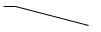
6
12
13
7 
8 |
14 |
|
|
9 |
|
3
2
|
|
|
DOWNFLOW/HORIZONTAL |
|
1 |
|
|
FURNACE COMPONENTS |
|
|
|
|
|
|
|
|
|
1 |
Manual-Reset Auxiliary Limit Switch |
|
|
|
|
(When Used) |
2 |
|
|
2 |
Blower and Blower Motor |
|
|
|
3 |
Relief Box |
|
|
|
4 |
Gas Valve Control Knob or Electric Switch |
|
|
8 |
|
(On/Off) |
|
|
|
5 |
Gas Valve |
|
9 |
|
6 |
Gas Burner |
3 |
|
|
7 |
Rating Plate |
|
|
|
8 |
Blower Door Safety Switch |
4 |
|
10 |
9 |
Blocked Vent Safeguard Tube and Switch |
|
|
10 |
Gas Manifold |
|
|
|
|
||
5 |
11 |
11 |
Manual Reset Limit Switch (2) |
|
|
6 |
|
12 |
Hot Surface Ignitor |
|
|
|
||
|
7 |
|
13 |
Flame Sensor |
|
12 |
|
|
|
|
13 |
|
|
|
4
IMPORTANT FACTS
Your furnace must have adequate airflow for efficient combustion and safe ventilation. Do not enclose it in an airtight room or “seal’’ it behind solid doors. To minimize the possibility of serious personal injury, fire, damage to your furnace, or improper operation; carefully follow these safety rules:
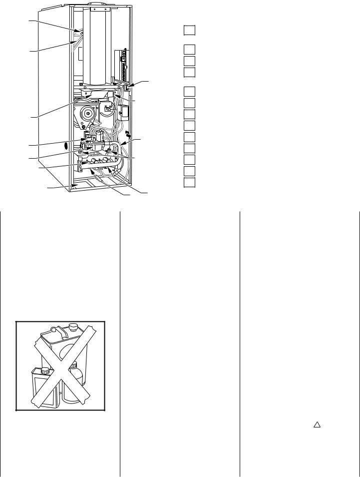
• Keep the area around your furnace free of combustible materials, gasoline, and other flammable liquids and vapors.
5
•Do not cover the furnace, store trash or debris near it, or in any way block the flow of fresh air to the unit.
•Combustion air must be clean and uncontaminated with chlorine or fluorine. These compounds are present in
many products around the home, such as: water softener salts, laundry bleaches, detergents, adhesives, paints, varnishes, paint strippers, waxes, and plastics.
Make sure the combustion air for your furnace does not contain any of these compounds. During remodeling be sure the combustion air is fresh and uncontaminated. If these compounds are burned in your furnace, the heat exchangers and metal vent system may deteriorate.
• A furnace installed in the attic or other insulated space must be kept free and clear of the insulating material. Examine the furnace area when installing the furnace or adding more insulation. Some materials may be combustible.
NOTE: Do not use this furnace if any part has been under water. Immediately call a qualified service technician to inspect the furnace and to replace any part of the control system and any gas control which has been under water.
NOTE: The qualified installer or agency must use only factoryauthorized re-placement parts, kits, and accessories when modifying or repairing this product.
This furnace contains safety devices which must be manually reset. If the fur-
nace is left unattended for an extended period of time, have it checked periodically for proper operation. This precaution will prevent problems associated with no heat, such as frozen water pipes, etc. See “Before You Request a Service Call’’ section in this manual.
SAFETY CONSIDERATIONS
Installing and servicing heating equipment can be hazardous due to gas and electrical components. Only trained and qualified personnel should install, repair, or service heating equipment.
Untrained personnel can perform basic maintenance functions such as cleaning and replacing air filters. All other operations must be performed by trained service personnel. Observe safety precautions in this manual, on tags, and on labels attached to the furnace and other safety precautions that may apply.
Recognize safety information: This is the safety-alert symbol ! . When you see this symbol on the furnace and in instructions or manuals, be alert to the potential for personal injury.
Understand the signal words—DAN- GER, WARNING, and CAUTION. These words are used with the
3
safety-alert symbol. DANGER identifies the most serious hazards which will result in severe personal injury or death. WARNING signifies hazards which could result in personal injury or death. CAUTION is used to identify unsafe practices which would result in minor personal injury or product and property damage.
STARTING YOUR
FURNACE
Instead of a continuously burning pilot flame, your furnace uses an automatic hot surface ignition system to light the burners each time the thermostat signals the furnace to start. Follow these important safeguards:
• Never attempt to manually light the burners with a match or other source of flame.
6
• Read and follow the operating instructions on the furnace, especially the item that reads as follows:
Wait 5 minutes to clear out any gas. Then smell for gas, including near the floor. If you smell gas, STOP! Follow “B’’ in the safety information above on this label. If you don’t smell gas, go to the next step.
• If a suspected malfunction occurs with your gas control system, such as the burners do not light when they should, refer to the shutdown procedures on the furnace, or in the next section, to turn off your system, then call your dealer as soon as possible.
! WARNING
Should overheating occur, or the gas valve fail to shut off the gas supply, turn off the manual gas valve (See Fig. 8) to the furnace BEFORE turning off the electrical supply. A failure to follow this warning could result in a fire or explosion, and personal injury or death.
• CHECK AIR FILTER: Before attempting to start your furnace, be sure the furnace filter is clean and in place. (See the maintenance section of this manual.) Then proceed as follows:
®
7
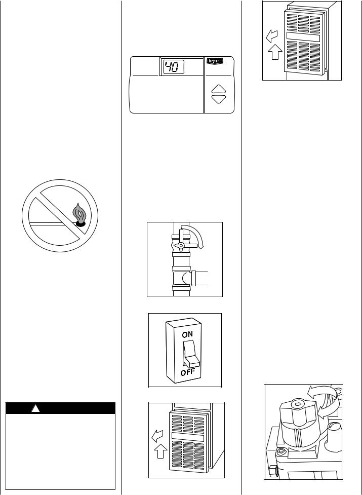
STEPS FOR STARTING YOUR FURNACE
1.Set your room thermostat to the lowest temperature setting. (See Fig. 7.)
2.Close the external manual gas valve. (See Fig. 8.)
3.Turn OFF the electrical supply to your furnace. (See Fig. 9.)
CL
O
S
E
8
9 |
10 |
4 |
11
4.Remove the furnace access door(s).
a.Downflow/Horizontal—remove blower door after removing
2 screws first, then remove the control door. (See Fig. 10.)
b.Upflow—remove control door. (See Fig. 11.)
5.The gas valve will have EITHER a control knob or control switch to turn off and on. Turn the control knob or switch on the gas valve to the OFF position and wait 5 minutes. (See Fig. 12 or 13.)
6.After waiting 5 minutes, turn the control knob or switch on the gas valve to the ON position. (See Fig. 14 or 15.)
7.Replace the access door(s). See Fig. 16 for upflow and Fig. 17 for downflow. Replace control door first on downflow furnaces. Then replace blower door (secure with 2 screws).
8.Turn ON the electrical supply to the furnace. (See Fig. 18.)
9.Open the external manual gas valve. (See Fig. 19.)
10.Set the room thermostat to a temperature slightly above the room temperature. This will automatically signal the furnace to start. The inducer motor will start, and the hot surface ignitor will energize. When hot, the ignitor will have an orange glow.
F |
OF |
12
 Loading...