


service and |
376CAV |
maintenance procedures |
395CAV |
GAS-FIRED |
Series G |
INDUCED-COMBUSTION FURNACE |
|
NOTE: Read the entire instruction manual before performing any |
|
service or maintenance. |
|
This symbol → indicates a change since the last issue. |
|
These procedures are for size 45,000 through 155,000 Btuh input |
|
units. |
|
Index |
Page |
SAFETY CONSIDERATIONS.................................................. |
1-2 |
ELECTROSTATIC DISCHARGE (ESD) PRECAUTIONS |
|
PROCEDURE ........................................................................... |
2 |
CARE AND MAINTENANCE................................................ |
2-11 |
Air Filter Arrangement.......................................................... |
2-3 |
Blower Motor and Wheel...................................................... |
3-4 |
Cleaning Heat Exchanger...................................................... |
4-5 |
Electrical Controls and Wiring ............................................. |
5-6 |
Troubleshooting ................................................................... |
6-11 |
Unit Wiring Diagram................................................................ |
8 |
Service Label ............................................................................ |
9 |
Troubleshooting Guide ...................................................... |
10-11 |
SAFETY CONSIDERATIONS |
|
Installing and servicing heating equipment can be hazardous due to |
|
gas and electrical components. Only trained and qualified person- |
|
nel should install, repair, or service heating equipment. |
|
Untrained personnel can perform basic maintenance functions |
|
such as cleaning and replacing air filters. All other operations must |
|
be performed by trained service personnel. When working on |
|
heating equipment, observe precautions in the literature, on tags, |
|
and on labels attached to or shipped with the unit and other safety |
|
precautions that may apply. |
|
→Follow all safety codes. In the United States, follow all safety codes including the National Fuel Gas Code (NFGC) NFPA No. 54-1996/ANSI Z223.1-1996. In Canada, refer to the current edition of the National Standard of Canada CAN/CGA-B149.1- and .2-M95 Natural Gas and Propane Installation Codes (NSCNGPIC). Wear safety glasses and work gloves. Have fire extinguisher available during start-up and adjustment procedures and service calls.
Recognize safety information. This is the safety-alert symbol  . When you see this symbol on the furnace and in instructions or
manuals, be alert to the potential for personal injury.
Understand the signal words DANGER, WARNING, and CAUTION. These words are used with the safety-alert symbol. DANGER identifies the most serious hazards which will result in severe personal injury or death. WARNING signifies a hazard which could result in personal injury or death. CAUTION is used to identify unsafe practices which would result in minor personal injury or product and property damage. NOTE is used to highlight suggestions which will result in enhanced installation, reliability, or operation.
Ð1Ð
Cancels: SP04-45 |
SP04-54 |
|
9-98 |
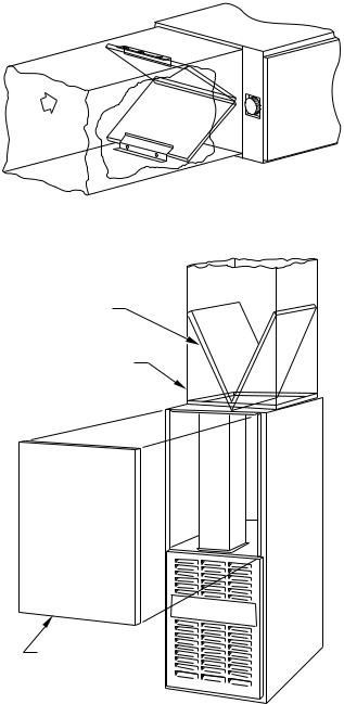
A94087
Fig. 1ÐModel 376CAV Horizontal
®

 ama
ama
CANADIAN GAS ASSOCIATION
A PP R O VED
R
A94086
Fig. 2ÐModel 376CAV
Downflow
REGISTERED QUALITY SYSTEM
A94085
Fig. 3ÐModel 395CAV
Upflow
WARNING: The ability to properly perform maintenance on this equipment requires certain expertise, mechanical skills, tools, and equipment. If you do not possess these, do not attempt to perform any maintenance on this equipment other than those procedures recommended in the User's Manual. FAILURE TO FOLLOW THIS WARNING COULD RESULT IN POSSIBLE DAMAGE TO THIS EQUIPMENT, SERIOUS PERSONAL INJURY, OR DEATH.
WARNING: Never store anything on, near, or in contact with the furnace, such as:
1.Spray or aerosol cans, rags, brooms, dust mops, vacuum cleaners, or other cleaning tools.
2.Soap powders, bleaches, waxes or other cleaning compounds, plastic or plastic containers, gasoline, kerosene, cigarette lighter fluid, dry cleaning fluids, or other volatile fluids.
3.Paint thinners and other painting compounds, paper bags, or other paper products.
A failure to follow this warning could result in corrosion of the heat exchanger, fire, personal injury, or death.
ELECTROSTATIC DISCHARGE (ESD) PRECAUTIONS
PROCEDURE
CAUTION: Electrostatic discharge can affect electronic components. Take precautions during furnace installation and servicing to protect the furnace electronic control. Precautions will prevent electrostatic discharges from personnel and hand tools which are held during the procedure. These precautions will help to avoid exposing the control to electrostatic discharge by putting the furnace, the control, and the person at the same electrostatic potential.
1.Disconnect all power to the furnace. DO NOT TOUCH THE CONTROL OR ANY WIRE CONNECTED TO THE CONTROL PRIOR TO DISCHARGING YOUR BODY'S ELECTROSTATIC CHARGE TO GROUND.
2.Firmly touch a clean, unpainted, metal surface of the furnace chassis which is close to the control. Tools held in a person's hand during grounding will be satisfactorily discharged.
3.After touching the chassis you may proceed to service the control or connecting wires as long as you do nothing that recharges your body with static electricity (for example; DO NOT move or shuffle your feet, DO NOT touch ungrounded objects, etc.).
4.If you touch ungrounded objects (recharge your body with static electricity), firmly touch furnace again before touching control or wires.
5.Use this procedure for installed and uninstalled (ungrounded) furnaces.
6.Before removing a new control from its container, discharge your body's electrostatic charge to ground to protect the control from damage. If the control is to be installed in a furnace, follow items 1 through 5 before bringing the control or yourself into contact with the furnace. Put all used AND new controls into containers before touching ungrounded objects.
7.An ESD service kit (available from commercial sources) may also be used to prevent ESD damage.
CARE AND MAINTENANCE
For continuing high performance and to minimize possible equipment failure, it is essential that periodic maintenance be performed on this equipment. Consult your local dealer as to the proper frequency of maintenance and the availability of a maintenance contract.
Ð2Ð
WARNING: Turn off the gas and electrical supplies to the unit before performing any maintenance or service. Follow the operating instructions on label attached to furnace. A failure to follow this warning could result in personal injury.
The minimum maintenance that should be performed on this equipment is as follows:
1.Check and clean air filter each month or more frequently if required. Replace if torn.
2.Check blower motor and wheel for cleanliness each heating and cooling season. Clean and lubricate as necessary.
3.Check electrical connections for tightness and controls for proper operation each heating season. Service as necessary.
CAUTION: As with any mechanical equipment, personal injury can result from sharp metal edges, etc., therefore, be careful when removing parts.
A.Air Filter Arrangement
The air filter arrangement may vary depending on the application. Refer to Table 1 or 2 for filter size information.
TABLE 1ÐFILTER SIZE INFORMATION FOR DOWNFLOW/HORIZONTAL FURNACES (IN.)
FURNACE |
FILTER QUANTITY |
FILTER |
CASING WIDTH |
AND SIZE |
TYPE |
14-3/16 |
(2) 14 X 20 X 1 |
Cleanable |
17-1/2 |
(2) 14 X 20 X 1 |
Cleanable |
21 |
(2) 16 X 20 X 1 |
Cleanable |
24-1/2 |
(2) 16 X 20 X 1 |
Cleanable |
|
|
|
TABLE 2ÐFILTER SIZE INFORMATION FOR UPFLOW
FURNACES (IN.)
FURNACE |
FILTER QUANTITY AND SIZE |
FILTER |
|
CASING WIDTH |
Side Return |
Bottom Return |
TYPE |
14-3/16 |
(1) 16 X 25 X 1* |
(1) 14 X 25 X 1 |
Cleanable |
17-1/2 |
(1) 16 X 25 X 1* |
(1) 16 X 25 X 1 |
Cleanable |
21 |
(1) 16 X 25 X 1 |
(1) 20 X 25 X 1* |
Cleanable |
24-1/2 |
(2) 16 X 25 X 1* |
(1) 24 X 25 X 1 |
Cleanable |
* Factory-provided with the furnace. Filters may be field modified as required by cutting and folding the frame as indicated on the filter.
WARNING: Never operate unit without a filter or with filter access door removed. A failure to follow this warning could result in fire, personal injury, or death.
AIRFLOW
Fig. 4ÐHorizontal Filter Arrangement
AIRFLOW 
INSTALLATION
POSITION
OF FILTERS
RETURN-AIR
PLENUM
ACCESS DOOR
A88486
Fig. 5ÐDownflow Filter Arrangement
1.Downflow/Horizontal
Each furnace requires 2 filters which are installed in the return-air duct. (See Fig. 4 and 5.) To remove filters for cleaning or replacement, proceed as follows:
a.Disconnect electrical power before removing blower access door.
b.Remove 2 screws from front of door and remove blower access door.
c.Reach up behind top plate, tilt filters toward center of return-air plenum, remove filters, and clean as needed. Replace if torn.
d.Furnaces are equipped with permanent, washable filters. Clean filters with tap water. Spray water through filter in opposite direction of airflow.
e.Rinse and let dry. Oiling or coating of filters is not recommended or required.
f.Reinstall filters.
Ð3Ð
g.Replace blower access door.
h.Restore electrical power to furnace.
2.Upflow
Each furnace requires 1 or 2 filters which are installed in the blower compartment. (See Fig. 6.) To remove filters for cleaning or replacement, proceed as follows:
a.Disconnect electrical power before removing access doors.
b.Remove blower and control access doors.
c.Release filter retainer from clip at front of furnace casing. (See Fig. 6.) For side return, clips may be used on either or both sides of the furnace.
d.Slide filter(s) out.
e.Furnaces are equipped with permanent, washable filters. Clean filters with tap water. Spray water through filter in opposite direction of airflow.
f.Rinse and let dry. Oiling or coating of filter is not recommended or required.
g.Reinstall filter(s).
h.Replace blower and control access doors.
i.Restore electrical power to furnace.
B. Blower Motor and Wheel
For long life, economy, and high efficiency, clean accumulated dirt and grease from the blower wheel and motor annually.
The following steps should be performed by a qualified service technician.
Some motors have prelubricated sealed bearings and require no lubrication. These motors can be identified by the absence of oil ports on each end of the motor. For those motors with oil ports, lubricate motor every 5 years if motor is used on intermittent operation (thermostat FAN in AUTO mode), or every 2 years if motor is in continuous operation (thermostat FAN in ON mode).
NOTE: Remember to disconnect the electrical supply before removing access doors.
Clean and lubricate as follows:
1.Remove 2 screws from blower access door (downflow/horizontal furnace only) and remove blower access door.
2.Remove vent pipe enclosure (downflow/horizontal furnace only) and disconnect short piece of vent pipe from relief box.
3.Disconnect wires from auxiliary limit on blower housing (downflow/horizontal furnace only).
4.Remove control.
5.Disconnect electrical leads from control. (See Fig. 6 or 7.) Note location of wires for reassembly.
6.Remove screws holding blower assembly to blower deck and slide blower assembly out of furnace.
7.Loosen screw in strap holding motor capacitor to blower housing and slide capacitor out from under strap.
8.Mark blower wheel, motor, and motor support in relation to blower housing before disassembly to ensure proper reassembly.
9.Loosen setscrew(s) holding blower wheel on motor shaft.
10.Remove bolts holding motor mount to blower housing and slide motor and mount out of housing. Disconnect ground wire attached to blower housing before removing motor.
11.Lubricate motor (when oil ports are provided).
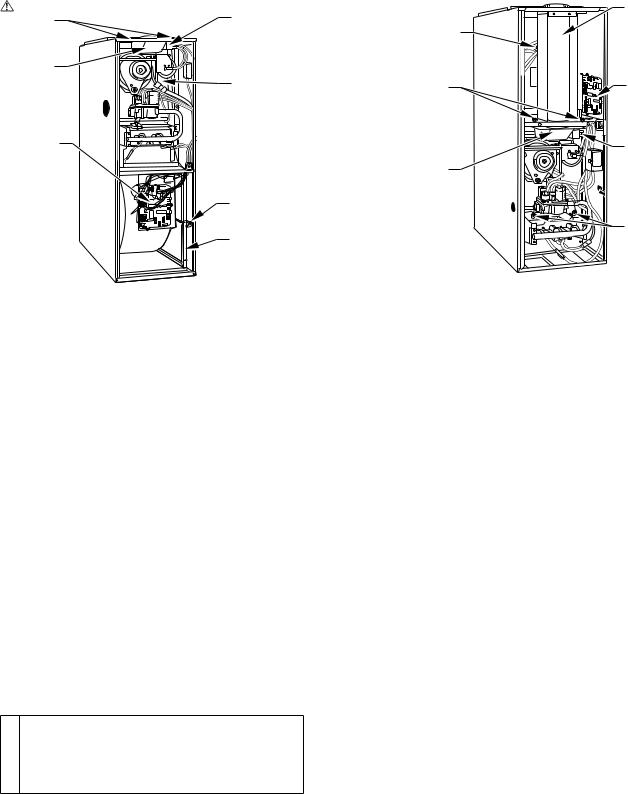
MOUNTING
SCREWS
RELIEF
BOX
CONTROL
 G R Y W
BLOCKED VENT SAFEGUARD
FLUE COLLECTOR BOX
FILTER RETAINER
WASHABLE FILTER
A98528
→Fig. 6ÐModel 395CAV Upflow
a.Remove dust caps or plugs from oil ports located at each end of motor.
b.Use a good grade of SAE 20 nondetergent motor oil and put 1 teaspoon, 5 cc, 3/16 oz, or 16 to 25 drops in each oil port. Do not over-oil.
c.Allow time for total quantity of oil to be absorbed by each bearing.
d.Wipe excess oil from motor housing.
e.Replace dust caps or plugs on oil ports.
12.Remove blower wheel from housing.
a.Mark cutoff location to ensure proper reassembly.
b.Remove screws holding cutoff plate and remove cutoff plate from housing.
c.Lift blower wheel from housing through opening.
13.Clean blower wheel and motor using a vacuum cleaner with soft brush attachment. Do not remove or disturb balance weights (clips) on blower wheel blades. The blower wheel should not be dropped or bent as balance will be affected.
14.Reinstall blower wheel by reversing items 12 a through c. Be sure wheel is positioned for proper rotation.
15.Reassemble motor and blower by reversing items 5 through 10. If motor has ground wire, be sure it is connected as before.
CAUTION: Be sure the motor is properly positioned in the blower housing. The motor oil ports must be at a
minimum of 45° above the horizontal centerline of the motor after the blower assembly has been reinstalled in the furnace.
16.Reinstall blower assembly in furnace.
17.Reinstall control. Connect blower electrical leads to control. Please note that the common wire connection is 3/16 in. and all other wire connections are 1/4 in. for assembly. DO NOT FORCE.
18.Reconnect wires to auxiliary limit switch on blower housing (downflow/horizontal furnace only).
19.Reinstall vent pipe and enclosure (downflow/horizontal furnace only).
Ð4Ð
|
VENT PIPE |
|
ENCLOSURE |
AUXILIARY |
|
LIMIT |
|
SWITCH |
|
(WHEN USED) |
|
MOUNTING |
CONTROL |
SCREWS |
BOARD |
|
BLOCKED |
|
VENT |
RELIEF |
SAFEGUARD |
BOX |
|
|
MANUAL |
|
RESET LIMIT |
|
SWITCHES |
|
A98529 |
→Fig. 7ÐModel 376CAV Downflow
20.Turn on electrical power and check for proper rotation and speed changes between heating and cooling.
21.Replace blower access door. Secure with 2 screws (downflow/horizontal furnace only).
C.Cleaning Heat Exchanger
The following steps should be performed by a qualified service technician.
NOTE: Deposits of soot and carbon indicate the existence of a problem which needs to be corrected. Take action to correct the problem.
If it becomes necessary to clean the heat exchanger because of carbon deposits, soot, etc., proceed as follows:
1.Turn off gas and electrical power to furnace.
2.Remove 2 screws from front of blower access door (downflow/horizontal furnace only) and remove control and blower access doors.
3.Remove vent pipe enclosure (downflow/horizontal furnace only) and disconnect vent pipe from relief box.
4.Remove 2 screws that secure relief box. (See Fig. 6 or 7.)
5.Disconnect wires to the following components.
→a. Blocked vent safeguard
b.Inducer motor
c.Pressure switch
d.Limit overtemperature switch(es)
e.Gas valve
f.Hot surface ignitor
g.Flame-sensing electrode
h.Two wiring connectors leading to control
6.Remove 8 screws that secure flue collector box to center panel. Be careful not to damage sealant.
7.Remove complete inducer assembly from furnace, exposing flue openings.
8.Clean cells using field-provided small wire brush, steel spring cable, reversible electric drill, and vacuum cleaner.
a.Assemble wire brush and steel spring cable.
(1.) Use 48 in. of 1/4-in. diameter high-grade steel spring cable (commonly known as drain clean-out or Roto-Rooter cable).
 Loading...