


|
|
|
DELUXE 11 SEER |
591B (60 Hz) |
|
|
|
||
|
|
|
AIR CONDITIONER |
|
|
|
|
WITH PURON® (R-410A) |
Sizes 018 thru 060 |
|
|
|
||
|
|
|
||
|
|
|
||
|
|
|
|
|
Bryant’s Quantum Plus 591B with Puron® provides features which cannot be matched by any other family of equipment. The 591B is a Quantum Plus air conditioning system utilizing Bryant’s unique Puron refrigerant. The environmentally sound refrigerant allows you to make a responsible decision in the protection of the earth’s ozone layer. Bryant’s Quantum Plus systems meet the Energy Star® guidelines for energy efficiency.
AVAILABLE OPTIONS
Puron® Environmentally Sound Refrigerant —Is Bryant’s unique refrigerant designed to help protect the environment. Puron is an HFC refrigerant which does not contain chlorine that can harm the ozone layer. The most important advantage of Puron refrigerant is that it has not been banned in future air conditioning systems as the traditional refrigerant R-22 has been. Puron refrigerant is in service in thousands of systems proving highly reliable, environmentally sound performance.
Heavy Duty Inlet Grille—The DuraGuard™ coil protector, made of a coated steel wire grid with vertical 3/8 in. spacing, is designed to help protect the coil from inclement weather, vandalism, and incidental damage. It provides protection while not restricting airflow and maintaining ease of coil inspection and cleaning.
High Efficiency Performance—Is delivered through a combination of features including Bryant’s Puron refrigerant, unique scroll compressor, and advanced heat transfer surfaces. Efficiency ratings are 11 to 12.5 SEER (Seasonal Energy Efficiency Ratio). Sophisticated heat transfer surfaces utilized in Bryant’s 591B design allow heat to easily be transferred to the outdoor air and require less energy. The unique scroll compressor found in the 591B design performs quietly and adds to the overall efficiency of the system. Finally, Bryant’s unique Puron refrigerant operates more efficiently than ordinary R-22 refrigerant found in other systems. The efficiency levels provided by the 591B provide end users with lower costs of operation than traditional air conditioning systems.
Assured Future Service—By utilizing the environmentally sound refrigerant, Puron®, 591B models will remain serviceable
well into the future. The Clean Air Act of 1990 has placed a cap on production of most other refrigerants which has scheduled reductions beginning in 2004. The resulting cap in production ultimately results in a complete ban on many other refrigerants in new equipment by the year 2010. These changes, required by federal law, mean the supply of other refrigerants may be limited in the near future making Puron the correct choice when considering long term serviceability.
Highly Reliable Performance—Is delivered through the superior design of the system and componentry. The reliability of the existing Quantum Plus models has been proven to provide the lowest incidence of warranty service of any product in the Bryant family in the past few years of service. Long term reliability is assured through the use of both high and low pressure switches which will not allow the system to operate in the event of a significant change in operating pressure. In doing this, the system is protected from damage if an unusual condition arises. Finally, Bryant includes a special liquid line filter drier designed to trap moisture and contaminants which could otherwise shorten the life of the system.
Application Versatility—Bryant’s systems utilizing Puron refrigerant have the same application guidelines as other systems. Applications which include long line sets (50 to 175 ft) or applications which require the system to operate at low outdoor temperatures (below 55°F) are approved under Bryant’s standard guidelines.
Bryant Coils and Fan Coils to Complete the System—Bryant specially designs both the outdoor product and indoor coil products to operate with assured reliability and performance. A wide range of indoor coil options are listed in the ratings section of this publication.
Special Protective Devices—High and low pressure switches and internal protection in the compressor including temperature and current sensing overloads prevent operation under potentially damaging circumstances. A special liquid line filter drier designed to trap nearly 4 times the volume of contaminants of standard driers provides superior protection from moisture trapped in the system.
Electrical Range—208/230v, single phase.
Wide Range of Sizes—Available in seven sizes; 1-1/2, 2, 2-1/2, 3, 3-1/2, 4, and 5 tons.
Reliant Cabinet—Galvanized steel is coated with powder paint to provide a superior, long lasting appearance.
Totally Enclosed Fan Motor—Protected from adverse weather conditions.
Unit Design—Enhanced copper and aluminum heat transfer surfaces with vertical air discharge to direct air up and away from the area.
External Service Valves—Both service valves are back seating type valves which are externally located. These unique valves allow service technicians to evacuate or charge the system in less time than standard service valves.
Easy Serviceability—One panel provides access to electrical controls and compressor. Removal of wire dome gives access to fan motor and removal of the top gives access to the coil.
Agency Approvals—591B models are listed with UL, c-UL, ARI, CEC, and CSA-EEV. Special endorsements have also been awarded these products by Energy Star® which recognizes energy efficient products.
Limited Warranty—A standard five year warranty on parts with a 10 year limited warranty on the compressor. Optional warranties are available through your Bryant distributor.
Form No. PDS 591B.18.1
—2—
|
|
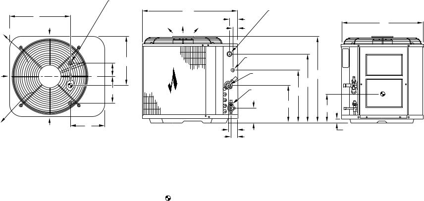
3/8" DIA. TIEDOWN KNOCKOUTS |
|
|
|
|
|
(2) PLACES |
|
|
|
|
L |
C |
FIELD POWER SUPPLY CONN. 7/8" DIA. |
|
|
|
2 1/2" |
HOLE WITH 1 1/8" DIA. KNOCKOUT |
|
||
|
AND 1 3/8" DIA. KNOCKOUT |
B |
|||
|
AIR IN |
AIR DISCHARGE |
|||
AIR DISCHARGE |
|
1 9/16" |
|
|
|
|
|
|
|
|
|
|
|
K |
FIELD CONTROL |
|
ACCESS |
|
|
SUPPLY CONN |
|
||
|
|
D |
7/8" DIA. HOLE |
|
PANEL |
|
|
H DIA. VAPOR |
A |
|
|
AIR IN |
|
C |
|
||
|
L |
LINE CONN. |
G |
|
|
|
|
|
|
|
|
|
|
E |
3/8" DIA. LIQUID |
F |
|
|
|
|
LINE CONN. |
|
|
|
|
|
10 1/2" |
M |
|
|
|
|
|
|
|
|
|
|
4 3/16" |
|
|
AIR DISCHARGE |
AIR IN |
J |
|
1 1/4" |
|
|
|
N |
|
DIMENSIONS |
|
|
|
|
1 3/4" |
|
|
|
|
|
|
|
|
NOTES:
1. |
ALLOW 30" CLEARANCE TO SERVICE SIDE OF UNIT, 48" ABOVE UNIT, 6" ON ONE |
|
SIDE, 12" ON REMAINING SIDE, AND 24" BETWEEN UNITS FOR PROPER AIRFLOW. |
2. |
MINIMUM OUTDOOR OPERATING AMBIENT IN COOLING MODE IS 55°F, |
|
(UNLESS LOW AMBIENT CONTROL IS USED) MAX. 125°F. |
3. |
SERIES DESIGNATION IS THE 14TH POSITION OF THE UNIT MODEL NUMBER. |
4. |
CENTER OF GRAVITY . |
A99067
DIMENSIONS (IN.)
|
|
|
|
|
|
|
UNIT DIMENSIONS |
|
|
|
|
|
|
MINIMUM |
||
UNIT |
|
|
|
|
|
|
|
|
|
|
|
|
|
|
|
MOUNTING |
|
|
|
|
|
|
|
|
|
|
|
|
|
|
|
||
SIZE |
SERIES |
A |
B |
C |
D |
E |
F |
G |
|
H |
J |
K |
L |
M |
N |
PAD DIMENSIONS |
018 |
A |
23-13/16 |
22-1/2 |
27-1/2 |
2-13/16 |
6-15/16 |
13-15/16 |
18-3/8 |
|
5/8 |
8-3/16 |
12-1/2 |
14 |
16-1/2 |
2-3/8 |
20 x 32 |
|
|
|
|
|
|
|
|
|
|
|
|
|
|
|
|
|
024 |
A |
27-13/16 |
22-1/2 |
27-1/2 |
2-13/16 |
6-15/16 |
15-15/16 |
22-3/8 |
|
5/8 |
8-3/16 |
12-1/2 |
14 |
16-1/2 |
2-15/16 |
20 x 32 |
030 |
A |
27-13/16 |
22-1/2 |
27-1/2 |
2-13/16 |
6-15/16 |
15-15/16 |
22-3/8 |
|
3/4 |
8-3/16 |
12-1/2 |
14 |
16-1/2 |
2-15/16 |
20 x 32 |
|
|
|
|
|
|
|
|
|
|
|
|
|
|
|
|
|
036 |
A |
33-13/16 |
22-1/2 |
27-1/2 |
2-13/16 |
6-15/16 |
21-15/16 |
28-3/8 |
|
3/4 |
8-3/16 |
12-1/2 |
14 |
17-1/2 |
2-15/16 |
20 x 32 |
|
|
|
|
|
|
|
|
|
|
|
|
|
|
|
|
|
042 |
A |
27-13/16 |
30 |
33 |
5-1/16 |
9-11/16 |
15-15/16 |
22-3/8 |
|
7/8 |
8-3/16 |
18-1/2 |
19-3/4 |
13 |
2-15/16 |
26 x 32 |
048 |
A |
27-13/16 |
30 |
33 |
5-1/16 |
9-11/16 |
15-15/16 |
22-3/8 |
|
7/8 |
8-3/16 |
18-1/2 |
19-3/4 |
13 |
2-15/16 |
26 x 32 |
|
|
|
|
|
|
|
|
|
|
|
|
|
|
|
|
|
060 |
A |
39-13/16 |
30 |
33 |
5-1/16 |
9-11/16 |
27-15/16 |
34-3/8 |
|
7/8 |
8-3/16 |
17-3/4 |
19 |
17-3/4 |
2-15/16 |
26 x 32 |
RECOMMENDED TUBE DIAMETERS
|
Liquid Tube Diameter (In.) |
Vapor Tube Diameter (In.) |
||
UNIT |
0 to 50 Ft |
|
0 to 50 Ft |
Long-Line Applications* |
SIZE |
Tube Length |
Long-Line Applications* |
Tube Length |
(Maximum Diameter) |
018 |
|
|
5/8 |
3/4 |
024 |
|
|
5/8 |
3/4 |
|
|
|
|
|
030, 036 |
3/8 |
3/8 |
3/4 |
7/8 |
|
|
|
|
|
042, 048 |
|
|
7/8 |
1-1/8 |
060 |
|
|
1-1/8 |
1-1/8 |
* For tube sets greater than 50 ft, consult Application Guideline and Service Manual— Air Conditioners and Heat Pumps Using Puron® Refrigerant.
CHECK-FLO-RATER® PISTON
|
PISTON* |
UNIT SIZE–SERIES |
IDENTIFICATION NO. |
018-A |
49 |
|
|
024-A |
59 |
030-A |
63 |
|
|
036-A |
67 |
|
|
042-A |
73 |
048-A |
78 |
|
|
060-A |
90 |
*Piston listed is for any approved non-capillary tube coil combination. Piston is shipped with outdoor unit and must be installed in an approved indoor coil.
CHARGING SUBCOOLING (TXV-TYPE EXPANSION DEVICE*)
UNIT SIZE–SERIES |
REQUIRED SUBCOOLING (°F) |
018-A |
15 |
024-A |
15 |
|
|
030-A |
16 |
|
|
036-A |
18 |
042-A |
18 |
|
|
048-A |
16 |
|
|
060-A |
14 |
* Must be a Puron® approved hard shutoff TXV.
As an ENERGY STAR® partner, Bryant Heating & Cooling Systems has determined that this product meets the ENERGY
STAR® guidelines for energy efficiency.
T |
U |
C |
|
A |
|
F |
|
U |
|
N |
|
A |
|
M |
|
R
E
R
|
|
|
D |
|
|
FIE |
|
|
|
TI |
|
|
R |
|
|
E |
|
|
|
C |
|
|
|
|
|
Y |
|
IT |
A |
R |
|
|
|
|
|
N |
|
|
|
U |
|
|
|
T |
|
|
|
|
|
|
O A |
|
|
|
|
|
|
RI |
|
|
|
|
|
|
|
AS |
|
|
|
|
|
|
C |
|
||||
AIR |
O |
|
||||
C |
M |
|
||||
|
P |
|
||||
|
O |
L |
|
|||
|
N |
|
||||
|
D |
Y |
|
|
|
|
|
I |
I |
|
|
|
|
|
T |
|
|
|
||
|
O |
N |
|
|
|
|
|
I |
|
|
|
|
|
|
N |
G |
|
|
|
|
|
I |
W |
|
|
|
|
|
N |
|
|
|
||
|
G |
I |
|
|
|
|
|
|
T |
|
|
|
|
|
|
H |
|
|
|
|
|
|
|
|
|
||
A RI
S
E |
T |
|
|
QUIPMEN |
0 |
|
|
|
|
1 |
|
|
2 |
|
|
D |
|
TANDAR |
|
|
CERTIFICATION APPLIES ONLY |
REGISTERED QUALITY SYSTEM |
WHEN THE COMPLETE SYSTEM |
|
IS LISTED WITH ARI. |
|
— 3—
SPECIFICATIONS
UNIT SIZE-SERIES |
018-A |
024-A |
|
030-A |
036-A |
||||
|
|||||||||
|
|
|
|
|
|
|
|
|
|
Operating Weight (Lb) |
168 |
178 |
|
188 |
198 |
|
|||
|
|
|
|
|
|
|
|
|
|
ELECTRICAL |
|
|
|
|
|
|
|||
Unit Volts— Hertz— Phase |
|
208/230-60-1 |
|
|
|||||
|
|
|
|
|
|
|
|
|
|
Operating Voltage Range* |
|
|
187-253 |
|
|
||||
|
|
|
|
|
|
|
|
|
|
Compressor— Rated Load Amps |
10.3 |
13.5 |
|
15.4 |
17.9 |
|
|||
|
|
|
|
|
|
|
|
|
|
|
|
|
Locked Rotor Amps |
51.0 |
61.0 |
|
73.0 |
100.0 |
|
|
|
|
|
|
|
|
|
|
|
Condenser Fan Motor— Full Load Amps |
0.50 |
0.75 |
|
0.75 |
1.40 |
|
|||
|
|
|
|
|
|
|
|
|
|
Min Unit Ampacity for Wire Sizing |
13.4 |
17.4 |
|
19.2 |
20.1 |
|
|||
|
|
|
|
|
|
|
|
|
|
Min Wire Size (60°C Copper) AWG† |
14 |
14 |
|
14 |
12 |
|
|||
|
|
|
|
|
|
|
|
|
|
Min Wire Size (75°C Copper) AWG† |
14 |
14 |
|
14 |
12 |
|
|||
|
|
|
|
|
|
|
|
|
|
Max Wire Length (Ft) (60°C Copper)‡ |
56 |
44 |
|
39 |
52 |
|
|||
|
|
|
|
|
|
|
|
|
|
Max Wire Length (Ft) (75°C Copper)‡ |
54 |
42 |
|
37 |
50 |
|
|||
|
|
|
|
|
|
|
|
|
|
Max Branch Circuit Fuse or |
|
|
|
|
|
|
|||
Circuit Breaker Size (Amps) |
20 |
30 |
|
30 |
40 |
|
|||
|
|
|
|
|
|
|
|
|
|
COMPRESSOR & REFRIGERANT |
|
|
|
|
|
|
|||
Compressor— Type |
|
|
Scroll |
|
|
||||
|
|
|
|
|
|
|
|
|
|
|
|
|
Manufacturer |
|
|
Copeland |
|
|
|
|
|
|
|
|
|
|
|
||
Temperature & Current Protection |
|
Internal Line Break |
|
|
|||||
|
|
|
|
|
|
|
|
||
Refrigerant— Type |
|
Puron® (R-410A) |
|
|
|||||
|
|
|
|
|
|
|
|
|
|
|
|
Amount (Lb) |
4.15 |
4.66 |
|
5.28 |
6.13 |
|
|
|
|
|
|
|
|
|
|
|
|
CONDENSER COIL & FAN |
|
|
|
|
|
|
|||
Coil Face Area (Sq Ft) |
7.27 |
8.72 |
|
8.72 |
10.9 |
|
|||
|
|
|
|
|
|
|
|
|
|
Fins per In.— Rows— Circuits |
20— 1— 1 |
25— 1— 2 |
|
25— 1— 2 |
25— 1— 2 |
||||
|
|
|
|
|
|
|
|
|
|
Fan Motor— HP (PSC) & RPM |
1/12 & 1100 |
1/10 & 1100 |
|
1/10 & 1100 |
1/10 & 1100 |
|
|||
|
|
|
|
|
|
|
|
|
|
Volts— Hertz— Phase |
|
208/230-60-1 |
|
|
|||||
|
|
|
|
|
|
|
|
|
|
Condenser Airflow (CFM) |
1700 |
2000 |
|
2000 |
2500 |
|
|||
|
|
|
|
|
|
|
|
|
|
OPTIONAL EQUIPMENT |
|
|
|
|
|
|
|||
Support Feet |
|
KSASF0101AAA |
|
|
|||||
|
|
|
|
|
|
|
|
||
Coastal Filter |
|
KAACF0701SML |
|
|
|||||
Time Delay Relay |
|
KAATD0101TDR |
|
|
|||||
|
|
|
|
|
|
|
|
||
Cycle Protector |
|
KSACY0101AAA |
|
|
|||||
|
|
|
|
|
|
|
|
||
Crankcase Heater |
|
KAACH1201AAA |
|
|
|||||
|
|
|
|
|
|
|
|
|
|
Start Assist— Capacitor/Relay Type |
KSAHS1701AAA |
|
|
KSAHS1501AAA |
|
|
|||
|
|
|
|
|
|
|
|
||
Start Assist— PTC Type |
|
KAACS0201PTC |
|
|
|||||
|
|
|
|
|
|
|
|
|
|
TXV (Hard Shutoff) |
|
KSATX0201HSZ |
|
|
KSATX0301HSZ |
||||
|
|
|
|
|
|
|
|
||
Piston Body |
|
KSAPX0101PIS |
|
|
|||||
|
|
|
|
|
|
|
|
|
|
Filter Drier (Suction Line) |
|
|
KH45LG140 |
|
|
||||
|
|
|
|
|
|
|
|
||
Evaporator Freeze Thermostat†† (RCD) |
|
KAAFT0101AAA |
|
|
|||||
|
|
|
|
|
|
|
|
||
Liquid-Line Solenoid Valve |
|
KAALS0201LLS |
|
|
|||||
|
|
|
|
|
|
|
|
||
Winter Start Control†† |
|
KAAWS0101AAA |
|
|
|||||
|
|
|
|
|
|
|
|
||
Low-Ambient Pressure Switch |
|
KSALA0301410 |
|
|
|||||
|
|
|
|
|
|
|
|
|
|
MotorMaster® Control** (RCD) |
|
|
32LT660004 |
|
|
||||
|
|
|
|
|
|
|
|
|
|
Ball Bearing Fan Motor (RCD) |
|
|
HC34GE232 |
|
|
||||
|
|
|
|
|
|
|
|
|
|
Thermostat— Auto Changeover, |
|
|
|
|
|
|
|||
Non-Programmable, °F/°C, |
|
|
|
|
|
|
|||
1-Stage Heat, 1-Stage Cool |
|
TSTATBBNAC01-B |
|
|
|||||
Thermostat— Auto Changeover, |
|
|
|
|
|
|
|||
7-Day Programmable, °F/°C, |
|
|
|
|
|
|
|||
1-Stage Heat, 1-Stage Cool |
|
TSTATBBPAC01-B |
|
|
|||||
Thermidistat™ Control— |
|
|
|
|
|
|
|||
Programmable Thermostat with Humidity Control |
|
TSTATBBPRH01-B |
|
|
|||||
Builder’s Thermostat— Manual Changeover, |
|
|
|
|
|
|
|||
Non-Programmable, °F/°C, |
|
|
|
|
|
|
|||
1-Stage Heat, 1-Stage Cool |
|
TSTATBBBAC01-B |
|
|
|||||
|
|
|
|
|
|
|
|
||
Outdoor Air Temperature Sensor |
|
TSTATXXSEN01-B |
|
|
|||||
|
|
|
|
|
|
|
|
||
Backplate for Non-Programmable Thermostat |
|
TSTATXXNBP01 |
|
|
|||||
|
|
|
|
|
|
|
|
||
Backplate for Programmable Thermostat |
|
TSTATXXPBP01 |
|
|
|||||
|
|
|
|
|
|
|
|
||
Backplate for Builder’s Thermostat |
|
TSTATXXBBP01 |
|
|
|||||
|
|
|
|
|
|
|
|
||
Thermostat Conversion Kit (4 to 5 wire)— 10 Pack |
|
TSTATXXCNV10 |
|
|
|||||
|
|
|
|
|
|
|
|
|
|
See notes on page 5.
— 4—
SPECIFICATIONS Continued
UNIT SIZE-SERIES |
042-A |
|
048-A |
|
060-A |
|||
Operating Weight (Lb) |
215 |
|
217 |
|
278 |
|||
|
|
|
|
|
|
|
|
|
ELECTRICAL |
|
|
|
|
|
|||
Unit Volts— Hertz— Phase |
|
208/230-60-1 |
|
|
||||
|
|
|
|
|
|
|
|
|
Operating Voltage Range* |
|
187-253 |
|
|
||||
|
|
|
|
|
|
|
|
|
Compressor— Rated Load Amps |
19.9 |
|
24.4 |
|
30.1 |
|||
|
|
|
|
|
|
|
|
|
|
|
|
Locked Rotor Amps |
127.0 |
|
131.0 |
|
172.0 |
|
|
|
|
|
|
|
|
|
Condenser Fan Motor— Full Load Amps |
1.10 |
|
1.40 |
|
1.40 |
|||
|
|
|
|
|
|
|
|
|
Min Unit Ampacity for Wire Sizing |
24.4 |
|
26.7 |
|
35.9 |
|||
|
|
|
|
|
|
|
|
|
Min Wire Size (60°C Copper) AWG† |
10 |
|
8 |
|
8 |
|||
|
|
|
|
|
|
|
|
|
Min Wire Size (75°C Copper) AWG† |
10 |
|
10 |
|
8 |
|||
|
|
|
|
|
|
|
|
|
Max Wire Length (Ft) (60°C Copper)‡ |
77 |
|
97 |
|
80 |
|||
|
|
|
|
|
|
|
|
|
Max Wire Length (Ft) (75°C Copper)‡ |
73 |
|
59 |
|
76 |
|||
|
|
|
|
|
|
|
|
|
Max Branch Circuit Fuse or |
|
|
|
|
|
|||
Circuit Breaker Size (Amps) |
40 |
|
50 |
|
60 |
|||
|
|
|
|
|
|
|
|
|
COMPRESSOR & REFRIGERANT |
|
|
|
|
|
|||
Compressor— Type |
|
|
Scroll |
|
|
|||
|
|
|
|
|
|
|
|
|
|
|
|
Manufacturer |
|
|
Copeland |
|
|
|
|
|
|
|
|
|
|
|
Temperature & Current Protection |
|
|
Internal Line Break |
|
|
|||
|
|
|
|
|
|
|
|
|
Refrigerant— Type |
|
|
Puron® (R-410A) |
|
|
|||
|
|
|
|
|
|
|
|
|
|
Amount (Lb) |
6.33 |
|
6.83 |
|
7.93 |
||
|
|
|
|
|
|
|
|
|
CONDENSER COIL & FAN |
|
|
|
|
|
|||
Coil Face Area (Sq Ft) |
12.16 |
|
12.16 |
|
18.3 |
|||
|
|
|
|
|
|
|
|
|
Fins per In.— Rows— Circuits |
25— 1— 2 |
|
25— 1— 2 |
|
25— 1— 3 |
|||
|
|
|
|
|
|
|
|
|
Fan Motor— HP (PSC) & RPM |
1/5 & 825 |
|
1/4 & 1100 |
|
1/4 & 1100 |
|||
|
|
|
|
|
|
|
|
|
Volts— Hertz— Phase |
|
208/230-60-1 |
|
|
||||
|
|
|
|
|
|
|
|
|
Condenser Airflow (CFM) |
2800 |
|
3400 |
|
3400 |
|||
|
|
|
|
|
|
|
|
|
OPTIONAL EQUIPMENT |
|
|
|
|
|
|||
Support Feet |
|
|
KSASF0101AAA |
|
|
|||
|
|
|
|
|
|
|
|
|
Coastal Filter |
|
|
KAACF0801MED |
|
|
|||
|
|
|
|
|
|
|
|
|
Time Delay Relay |
|
|
KAATD0101TDR |
|
|
|||
|
|
|
|
|
|
|
|
|
Cycle Protector |
|
|
KSACY0101AAA |
|
|
|||
|
|
|
|
|
|
|
|
|
Crankcase Heater |
|
|
KAACH1201AAA |
|
|
|||
|
|
|
|
|
|
|
|
|
Start Assist— Capacitor/Relay Type |
|
KSAHS1501AAA |
|
KSAHS1601AAA |
||||
|
|
|
|
|
|
|
|
|
Start Assist— PTC Type |
|
|
KAACS0201PTC |
|
|
|||
|
|
|
|
|
|
|
|
|
TXV (Hard Shutoff) |
KSATX0301HSZ |
|
KSATX0401HSZ |
|
KSATX0501HSZ |
|||
|
|
|
|
|
|
|
|
|
Piston Body |
|
|
KSAPX0101PIS |
|
|
|||
|
|
|
|
|
|
|
|
|
Filter Drier (Suction Line) (RCD) |
|
|
KH45LG141 |
|
|
|||
|
|
|
|
|
|
|
|
|
Evaporator Freeze Thermostat†† |
|
|
KAAFT0101AAA |
|
|
|||
|
|
|
|
|
|
|
|
|
Liquid-Line Solenoid Valve |
|
|
KAALS0201LLS |
|
|
|||
|
|
|
|
|
|
|
|
|
Winter Start Control†† |
|
|
KAAWS0101AAA |
|
|
|||
|
|
|
|
|
|
|
|
|
Low-Ambient Pressure Switch |
|
|
KSALA0301410 |
|
|
|||
|
|
|
|
|
|
|
|
|
MotorMaster® Control** |
|
|
32LT660004 |
|
|
|||
|
|
|
|
|
|
|
|
|
Ball Bearing Fan Motor (RCD) |
HC38GE231 |
|
|
HC40GE232 |
||||
|
|
|
|
|
|
|
|
|
Thermostat— Auto Changeover, |
|
|
|
|
|
|||
Non-Programmable, °F/°C, |
|
|
|
|
|
|||
1-Stage Heat, 1-Stage Cool |
|
|
TSTATBBNAC01-B |
|
|
|||
|
|
|
|
|
|
|
|
|
Thermostat— Auto Changeover, |
|
|
|
|
|
|||
7-Day Programmable, °F/°C, |
|
|
|
|
|
|||
1-Stage Heat, 1-Stage Cool |
|
|
TSTATBBPAC01-B |
|
|
|||
|
|
|
|
|
|
|
|
|
Thermidistat™ Control— |
|
|
|
|
|
|||
Programmable Thermostat with Humidity Control |
|
|
TSTATBBPRH01-B |
|
|
|||
|
|
|
|
|
|
|
|
|
Builder’s Thermostat— Manual Changeover, |
|
|
|
|
|
|||
Non-Programmable, °F/°C, |
|
|
|
|
|
|||
1-Stage Heat, 1-Stage Cool |
|
|
TSTATBBBAC01-B |
|
|
|||
|
|
|
|
|
|
|
|
|
Outdoor Air Temperature Sensor |
|
|
TSTATXXSEN01-B |
|
|
|||
|
|
|
|
|
|
|
|
|
Backplate for Non-Programmable Thermostat |
|
|
TSTATXXNBP01 |
|
|
|||
|
|
|
|
|
|
|
|
|
Backplate for Programmable Thermostat |
|
|
TSTATXXPBP01 |
|
|
|||
|
|
|
|
|
|
|
|
|
Backplate for Builder’s Thermostat |
|
|
TSTATXXBBP01 |
|
|
|||
|
|
|
|
|
|
|
|
|
Thermostat Conversion Kit (4 to 5 wire)— 10 Pack |
|
|
TSTATXXCNV10 |
|
|
|||
|
|
|
|
|
|
|
|
|
*Permissible limits of the voltage range at which the unit will operate satisfactorily. Operation outside these limits may result in unit failure.
†If wire is applied at ambient greater than 30°C (86°F), consult Table 310-16 of the NEC (ANSI/NFPA 70).
The ampacity of nonmetallic-sheathed cable (NM), trade name ROMEX, shall be that of 60°C (140°F) conductors, per the NEC (ANSI/NFPA 70) Article 336-26. If other than uncoated (non-plated), 60 or 75°C (140 or 167°F) insulation, copper wire (solid wire for 10 AWG and smaller, stranded wire for larger than 10 AWG) is used, consult applicable tables of the NEC (ANSI/NFPA 70).
‡ Length shown is as measured 1 way along wire path between unit and service panel for a voltage drop not to exceed 2%.
**Fan motor with ball bearings required.
††See low-ambient controller Installation Instructions for application. N/A — Not Applicable.
NOTE: Copper wire must be used from service disconnect to unit. All motors/compressors contain internal overload protection.
—5—
ACCESSORY USAGE GUIDELINE
|
REQUIRED FOR |
REQUIRED FOR |
REQUIRED FOR |
|
|
LOW-AMBIENT |
LONG-LINE |
SEA COAST |
|
|
APPLICATIONS |
APPLICATIONS* |
APPLICATIONS |
|
ACCESSORY |
(Below 55°F) |
(Over 50 Ft) |
(Within 2 Miles) |
|
|
|
|
|
|
Crankcase Heater |
Yes |
Yes |
No |
|
|
|
|
|
|
Evaporator Freeze Thermostat |
Yes |
No |
No |
|
|
|
|
|
|
Winter Start Control |
Yes† |
No |
No |
|
|
|
|
|
|
Accumulator |
No |
No |
No |
|
|
|
|
|
|
Compressor Start Assist |
Yes |
Yes |
No |
|
Capacitor and Relay |
||||
|
|
|
||
|
|
|
|
|
MotorMaster® Control, |
|
|
|
|
or |
Yes |
No |
No |
|
Low-Ambient Pressure Switch |
|
|
|
|
|
|
|
|
|
Wind Baffle |
See Low-Ambient Instructions |
No |
No |
|
|
|
|
|
|
Coastal Filter |
No |
No |
Yes |
|
|
|
|
|
|
Support Feet |
Recommended |
No |
Recommended |
|
|
|
|
|
|
Liquid-Line Solenoid Valve |
|
See Long-Line |
|
|
or |
No |
Application |
No |
|
Hard Shutoff TXV |
|
Guideline |
|
|
|
|
|
|
|
Ball Bearing Fan Motor |
Yes‡ |
No |
No |
|
|
|
|
|
*For tubing line sets greater than 50 ft, refer to Application Guideline and Service Manual— Air Conditioning and Heat Pumps Using Puron® Refrigerant.
†Only when low-pressure switch is used.
‡ Required for low-ambient controller (full modulation feature) and MotorMaster® Control only.
ACCESSORY DESCRIPTION AND USAGE (Listed Alphabetically)
1.Ball Bearing Fan Motor
A fan motor with ball bearings which permits speed reduction while maintaining bearing lubrication.
SUGGESTED USE: Required on all units where Low-Ambient Controller (full modulation feature) or MotorMaster® Control has been added.
2.Coastal Filter
A mesh screen inserted under the top cover and inside base pan to protect the condenser coil from corrosive atmosphere without restricting airflow.
SUGGESTED USE: In geographic areas where salt damage could occur.
In areas with high pollution levels.
3.Compressor Start Assist—Capacitor/Relay Type
Start capacitor and start relay which gives a “hard” boost to compressor motor at each start-up.
SUGGESTED USE: Installations where interconnecting tube length exceeds 50 ft.
Installations where outdoor design temperature exceeds 105°F (40.6°C).
Installations where Liquid-Line Solenoid Valve or hard shutoff TXV has been added.
4.Compressor Start Assist—PTC Type
Solid-state electrical device which gives a “soft” boost to compressor motor at each start-up.
SUGGESTED USE: Installations with marginal power supply.
5.Crankcase Heater
An electric resistance heater which mounts to the base of the compressor to keep the lubricant warm during off cycles. Improves compressor lubrication
on restart and minimizes chance of refrigerant slugging. May or may not include a thermostat control. SUGGESTED USE: When interconnecting tube length exceeds 50 ft.
When unit will be operated below 55°F (12.8°C) outdoor air temperature. Use with Low-Ambient Controller. All commercial installations.
6.Cycle Protector
Solid state timing device which prevents compressor rapid recycling. Control provides an approximate 5-minute delay after power to the compressor has been interrupted for any reason, including normal room thermostat cycling.
SUGGESTED USE: Installations in areas where power interruptions are frequent.
Where user is likely to “play” with the room thermostat.
All commercial installations.
Installations where interconnecting tube length exceeds 50 ft.
High-rise applications.
7.Evaporator Freeze Thermostat
An SPST temperature actuated switch which stops unit operation when evaporator reaches freeze-up conditions.
SUGGESTED USE: All units where Winter Start Control has been added.
8.Filter Drier (Suction Line)
A device for removing contaminants from refrigerant circulating in an air conditioner: 1-direction flow. See Application Guideline and Service Manual for proper application.
SUGGESTED USE: All split-system air conditioners.
9.Liquid-Line Solenoid Valve (LSV)
An electrically operated shutoff valve to be installed at the outdoor or indoor unit (depending on tubing configuration) and which stops and starts refrigerant
liquid flow in response to compressor operation. Maintains a column of refrigerant liquid ready for action at next compressor operation cycle. NOTE: Compressor Start Assist— Capacitor/Relay Type must also be used. Do not use with hard shutoff TXV.
SUGGESTED USE: For improved system performance in air conditioners for certain combinations of indoor and outdoor units. Refer to ARI Unitary Directory. In certain long-line applications. Refer to Residential Split System Long-Line Application Guideline and Service Manual.
— 6—
ACCESSORY DESCRIPTION AND USAGE (Listed Alphabetically) Continued
10.Low-Ambient Pressure Switch
A long life pressure switch which is mounted to outdoor unit service valve. It is designed to cycle the outdoor fan motor in order to maintain head pressure within normal operating limits (approximately 200 psig to 365 psig). The control will maintain working head pressure at low-ambient temperatures down to 0°F (–17.8°C) when properly installed.
SUGGESTED USE: Cooling operation at outdoor temperatures below 55°F (12.8°C).
11.MotorMaster® Control
A fan speed control device activated by a temperature sensor. Designed to control condenser fan motor speed in response to the saturated, condensing temperature during operation in cooling mode only. For outdoor temperatures down to –20°F (–28.9°C), it maintains condensing temperature at
100°F ± 10°F (37.8°C ± 5.6°C).
SUGGESTED USE: Cooling operation at outdoor temperatures below 55°F (12.8°C).
All commercial installations.
12.Outdoor Air Temperature Sensor
A device that allows the temperature at a remote location (outdoors) to be displayed at the thermostat.
SUGGESTED USE: All Bryant programmable thermostats.
13.Piston Body
This piston body is to be used as a replacement for the FK4C Fan Coil R-22 thermostatic expansion valve when used with Puron® (R-410A) air conditioner
units. Use piston and piston ring shipped with outdoor unit for installations under 50 ft. SUGGESTED USE: All Puron® air conditioner installations matched with FK4C Fan Coils.
14.Support Feet
Four stick-on plastic feet which raise the unit 4 in. above the mounting pad. This allows sand, dirt, and other debris to be flushed from the unit base, minimizing corrosion.
SUGGESTED USE: For improved sound ratings.
Coastal installations.
Windy areas or where debris is normally circulating.
Rooftop installations.
15.Thermostatic Expansion Valve (TXV)
A modulating flow-control valve which meters refrigerant liquid flow rate into the evaporator in response to the superheat of the refrigerant gas leaving the evaporator. Kit includes valve, adapter tubes, and external equalizer tube. Hard shutoff valves are available. Do not use with Liquid-Line Solenoid Valve. NOTE: Compressor Start Assist— Capacitor/Relay Type must also be used. Do not use with Liquid Line Solenoid.
SUGGESTED USE: For improved system performance in cooling mode for certain combinations of indoor and outdoor units. Refer to ARI Unitary Directory. Required for use on all zoning systems.
16.Time-Delay Relay
An SPST delay relay which briefly continues operation of the indoor blower motor to provide additional cooling after the compressor cycles off.
SUGGESTED USE: For improved efficiency ratings for certain combinations of indoor and outdoor units. Refer to ARI Unitary Directory. Required for use on all zoning systems.
17.Winter Start Control
An SPST delay relay which bypasses the low-pressure switch for approximately 3 minutes to permit start-up for cooling operation under low-load
conditions.
SUGGESTED USE: All air conditioners where Low-Ambient Controller has been added.
SOUND POWER (dBA) (A-WTD, WITHOUT PURE TONE PENALTY)
|
SOUND |
|
|
OCTAVE BAND CENTER FREQUENCY (Hz) |
|
|
||
UNIT |
LEVEL |
|
|
|
|
|||
|
|
|
|
|
|
|
||
SIZE |
(dBA) |
125 |
250 |
500 |
1000 |
2000 |
4000 |
8000 |
018 |
74 |
52.0 |
63.5 |
65.5 |
69.0 |
64.5 |
58.0 |
51.0 |
|
|
|
|
|
|
|
|
|
024 |
74 |
57.5 |
64.0 |
67.5 |
68.5 |
66.0 |
60.5 |
53.0 |
|
|
|
|
|
|
|
|
|
030 |
75 |
58.5 |
66.0 |
69.0 |
69.0 |
66.0 |
61.0 |
53.5 |
036 |
77 |
61.0 |
67.5 |
71.0 |
71.5 |
70.0 |
67.0 |
58.0 |
|
|
|
|
|
|
|
|
|
042 |
77 |
61.0 |
67.0 |
68.5 |
66.5 |
63.5 |
56.5 |
51.5 |
|
|
|
|
|
|
|
|
|
048 |
78 |
61.5 |
68.0 |
71.5 |
72.0 |
68.5 |
65.5 |
60.0 |
060 |
78 |
61.5 |
65.5 |
69.0 |
69.5 |
65.0 |
64.0 |
56.0 |
— 7—
COMBINATION RATINGS
|
|
|
|
|
|
SEER |
|
|
|
|
|
TOT. |
FACTORY- |
|
Bryant Gas |
|
|
UNIT |
INDOOR |
|
SUPPLIED |
|
Furnace or |
|
|
|
|
CAP. |
ENHANCE- |
Standard |
Accessory |
Accessory |
|
||
SIZE-SERIES |
MODEL |
|
BTUH |
MENT |
Rating |
TDR† |
Puron TXV |
EER |
|
CC5A/CD5AA024* |
|
17,400 |
NONE |
10.5 |
11.0 |
11.0 |
9.95 |
|
CC5A/CD5AA018 |
|
17,000 |
NONE |
10.5 |
11.0 |
11.0 |
9.75 |
|
CC5A/CD5AW024 |
|
17,400 |
NONE |
10.5 |
11.0 |
11.0 |
9.95 |
|
CE3AA024 |
|
17,400 |
NONE |
10.5 |
11.0 |
11.0 |
10.00 |
|
CF5AA024 |
|
17,400 |
NONE |
10.5 |
11.0 |
11.0 |
10.00 |
|
CK3BA024 |
|
17,400 |
NONE |
10.5 |
11.0 |
11.0 |
10.05 |
|
CK5A/CK5BA018 |
|
17,000 |
NONE |
10.5 |
11.0 |
11.0 |
9.85 |
|
CK5A/CK5BA024 |
|
17,400 |
NONE |
10.5 |
11.0 |
11.0 |
10.05 |
|
CK5A/CK5BW024 |
|
17,400 |
NONE |
10.5 |
11.0 |
11.0 |
10.05 |
|
F(A,B)4AN(F,C)018 |
|
17,000 |
TDR |
11.0 |
— |
11.0 |
9.85 |
|
F(A,B)4AN(F,C)024 |
|
17,400 |
TDR |
11.0 |
— |
11.0 |
10.15 |
|
FC4BNF024 |
|
17,400 |
TDR&TXV |
11.0 |
— |
— |
10.15 |
|
FF1DNA018 |
|
17,000 |
TDR |
11.0 |
— |
11.0 |
10.10 |
|
FF1DNA024 |
|
17,400 |
TDR |
11.0 |
— |
11.0 |
10.00 |
|
FG3AAA024 |
|
17,300 |
NONE |
11.0 |
— |
11.0 |
9.85 |
|
FK4CNF001 |
|
17,400 |
TDR&TXV |
12.5 |
— |
— |
11.25 |
018-A |
FK4CNF002 |
|
17,800 |
TDR&TXV |
12.5 |
— |
— |
11.30 |
FV4ANF002 |
|
17,800 |
TDR&TXV |
12.5 |
— |
— |
11.30 |
|
|
|
|||||||
|
FX4ANF018 |
|
17,400 |
TDR&TXV |
11.0 |
— |
— |
10.15 |
|
|
COILS + 333(B,J)AV036060 VARIABLE SPEED FURNACE |
|
|
||||
|
CC5A/CD5AA018 |
|
16,800 |
TDR |
11.5 |
— |
11.5 |
10.55 |
|
CC5A/CD5AA024 |
|
17,400 |
TDR |
11.5 |
— |
11.5 |
10.85 |
|
CE3AA024 |
|
17,400 |
TDR |
11.5 |
— |
11.5 |
10.85 |
|
CK3BA024 |
|
17,400 |
TDR |
11.5 |
— |
11.5 |
11.15 |
|
CK5A/CK5BA018 |
|
17,000 |
TDR |
11.5 |
— |
11.5 |
10.85 |
|
CK5A/CK5BA024 |
|
17,400 |
TDR |
11.5 |
— |
11.5 |
11.15 |
|
|
COILS + 355MAV042060 VARIABLE SPEED FURNACE |
|
|
||||
|
CC5A/CD5AW024 |
|
17,400 |
TDR |
11.5 |
— |
11.5 |
10.85 |
|
CE3AA024 |
|
17,400 |
TDR |
11.5 |
— |
11.5 |
10.90 |
|
CK5A/CK5BW024 |
|
17,400 |
TDR |
11.5 |
— |
11.5 |
10.95 |
|
|
COILS + 355MAV042080 VARIABLE SPEED FURNACE |
|
|
||||
|
CC5A/CD5AW024 |
|
17,400 |
TDR |
11.5 |
— |
11.5 |
10.90 |
|
CC5A/CD5AA030* |
|
23,800 |
NONE |
10.5 |
11.0 |
11.0 |
9.70 |
|
CC5A/CD5AA024 |
|
23,400 |
NONE |
10.5 |
11.0 |
11.0 |
9.60 |
|
CC5A/CD5AW024 |
|
23,400 |
NONE |
10.5 |
11.0 |
11.0 |
9.60 |
|
CC5A/CD5AW030 |
|
23,800 |
NONE |
10.5 |
11.0 |
11.0 |
9.70 |
|
CE3AA024 |
|
23,400 |
NONE |
10.5 |
11.0 |
11.0 |
9.70 |
|
CE3AA030 |
|
23,800 |
NONE |
10.5 |
11.0 |
11.0 |
9.75 |
|
CF5AA024 |
|
23,400 |
NONE |
10.5 |
11.0 |
11.0 |
9.65 |
|
CK3BA024 |
|
23,400 |
NONE |
10.5 |
11.0 |
11.0 |
9.75 |
|
CK3BA030 |
|
23,800 |
NONE |
10.5 |
11.0 |
11.0 |
9.80 |
|
CK5A/CK5BA024 |
|
23,400 |
NONE |
10.5 |
11.0 |
11.0 |
9.75 |
|
CK5A/CK5BA030 |
|
23,800 |
NONE |
10.5 |
11.0 |
11.0 |
9.80 |
|
CK5A/CK5BW024 |
|
23,400 |
NONE |
10.5 |
11.0 |
11.0 |
9.75 |
|
CK5A/CK5BW030 |
|
23,800 |
NONE |
10.5 |
11.0 |
11.0 |
9.80 |
|
F(A,B)4AN(F,C)024 |
|
23,400 |
TDR |
11.0 |
— |
11.0 |
9.80 |
|
F(A,B)4AN(F,C)030 |
|
23,800 |
TDR |
11.0 |
— |
11.0 |
9.70 |
|
FC4BNF024 |
|
23,400 |
TDR&TXV |
11.0 |
— |
— |
9.80 |
|
FC4BNF030 |
|
23,800 |
TDR&TXV |
11.0 |
— |
— |
10.00 |
|
FF1(B,C,D)NA024 |
|
23,400 |
TDR |
11.0 |
— |
11.0 |
9.65 |
|
FF1(B,C,D)NA030 |
|
23,800 |
TDR |
11.0 |
— |
11.0 |
9.80 |
|
FG3AAA024 |
|
23,400 |
NONE |
10.5 |
— |
10.5 |
9.50 |
|
FK4CNF001 |
|
24,000 |
TDR&TXV |
12.0 |
— |
— |
10.75 |
|
FK4CNF002 |
|
24,000 |
TDR&TXV |
12.0 |
— |
— |
10.80 |
|
FK4CNF003 |
|
24,200 |
TDR&TXV |
12.5 |
— |
— |
11.05 |
|
FV4ANF002 |
|
24,000 |
TDR&TXV |
12.0 |
— |
— |
10.80 |
024-A |
FV4ANF003 |
|
24,200 |
TDR&TXV |
12.5 |
— |
— |
11.05 |
FX4ANF030 |
|
23,800 |
TDR&TXV |
11.0 |
— |
— |
10.00 |
|
|
|
COILS + 333(B,J)AV036060 VARIABLE SPEED FURNACE |
|
|
||||
|
CC5A/CD5AA024 |
|
23,400 |
TDR |
11.5 |
— |
11.5 |
10.30 |
|
CC5A/CD5AA030 |
|
23,800 |
TDR |
11.5 |
— |
11.5 |
10.50 |
|
CC5A/CD5AW030 |
|
23,800 |
TDR |
11.5 |
— |
11.5 |
10.50 |
|
CE3AA024 |
|
23,400 |
TDR |
11.5 |
— |
11.5 |
10.35 |
|
CE3AA030 |
|
23,800 |
TDR |
11.5 |
— |
11.5 |
10.55 |
|
CK3BA024 |
|
23,400 |
TDR |
11.5 |
— |
11.5 |
10.50 |
|
CK3BA030 |
|
23,800 |
TDR |
11.5 |
— |
11.5 |
10.60 |
|
CK5A/CK5BA024 |
|
23,400 |
TDR |
11.5 |
— |
11.5 |
10.50 |
|
CK5A/CK5BA030 |
|
23,800 |
TDR |
11.5 |
— |
11.5 |
10.60 |
|
CK5A/CK5BW030 |
|
23,800 |
TDR |
11.5 |
— |
11.5 |
10.60 |
|
|
COILS + 355MAV042060 VARIABLE SPEED FURNACE |
|
|
||||
|
CC5A/CD5AW024 |
|
23,400 |
TDR |
11.5 |
— |
11.5 |
10.25 |
|
CC5A/CD5AW030 |
|
23,800 |
TDR |
11.5 |
— |
11.5 |
10.50 |
|
CE3AA024 |
|
23,400 |
TDR |
11.5 |
— |
11.5 |
10.30 |
|
CE3AA030 |
|
23,800 |
TDR |
11.5 |
— |
11.5 |
10.50 |
|
CK3BA024 |
|
23,400 |
TDR |
11.5 |
— |
11.5 |
10.40 |
|
CK3BA030 |
|
23,800 |
TDR |
11.5 |
— |
11.5 |
10.50 |
|
CK5A/CK5BW024 |
|
23,400 |
TDR |
11.5 |
— |
11.5 |
10.40 |
|
CK5A/CK5BW030 |
|
23,800 |
TDR |
11.5 |
— |
11.5 |
10.50 |
|
|
COILS + 355MAV042080 VARIABLE SPEED FURNACE |
|
|
||||
|
CC5A/CD5AW024 |
|
23,400 |
TDR |
11.5 |
— |
11.5 |
10.35 |
|
CC5A/CD5AW030 |
|
23,800 |
TDR |
11.5 |
— |
11.5 |
10.60 |
See notes on page 14.
— 8—
COMBINATION RATINGS Continued
|
|
|
|
|
|
SEER |
|
|
|
|
|
TOT. |
FACTORY- |
|
Bryant Gas |
|
|
UNIT |
INDOOR |
|
SUPPLIED |
|
Furnace or |
|
|
|
|
CAP. |
ENHANCE- |
Standard |
Accessory |
Accessory |
|
||
SIZE-SERIES |
MODEL |
|
BTUH |
MENT |
Rating |
TDR† |
Puron TXV |
EER |
|
CE3AA024 |
|
23,400 |
TDR |
11.5 |
— |
11.5 |
10.40 |
024-A |
CE3AA030 |
|
23,800 |
TDR |
11.5 |
— |
11.5 |
10.60 |
CK5A/CK5BW024 |
|
23,400 |
TDR |
11.5 |
— |
11.5 |
10.60 |
|
|
|
|||||||
|
CK5A/CK5BW030 |
|
23,800 |
TDR |
11.5 |
— |
11.5 |
10.70 |
|
CC5A/CD5AA036* |
|
29,000 |
NONE |
10.5 |
11.0 |
11.0 |
9.75 |
|
CC5A/CD5AA030 |
|
28,000 |
NONE |
10.4 |
10.8 |
10.8 |
9.50 |
|
CC5A/CD5AW030 |
|
28,000 |
NONE |
10.4 |
10.8 |
10.8 |
9.50 |
|
CC5A/CD5AW036 |
|
29,000 |
NONE |
10.5 |
11.0 |
11.0 |
9.75 |
|
CE3AA030 |
|
28,000 |
NONE |
10.5 |
11.0 |
11.0 |
9.60 |
|
CE3AA036 |
|
28,200 |
NONE |
10.5 |
11.0 |
11.0 |
9.65 |
|
CF5AA036 |
|
28,200 |
NONE |
10.5 |
11.0 |
11.0 |
9.70 |
|
CK3BA030 |
|
28,000 |
NONE |
10.5 |
11.0 |
11.0 |
9.55 |
|
CK3BA036 |
|
29,000 |
NONE |
10.5 |
11.0 |
11.0 |
9.80 |
|
CK5A/CK5BA030 |
|
28,000 |
NONE |
10.5 |
11.0 |
11.0 |
9.55 |
|
CK5A/CK5BA036 |
|
29,000 |
NONE |
10.5 |
11.0 |
11.0 |
9.80 |
|
CK5A/CK5BT036 |
|
29,000 |
NONE |
10.5 |
11.0 |
11.0 |
9.80 |
|
CK5A/CK5BW030 |
|
28,000 |
NONE |
10.5 |
11.0 |
11.0 |
9.55 |
|
CK5A/CK5BW036 |
|
29,000 |
NONE |
10.5 |
11.0 |
11.0 |
9.80 |
|
F(A,B)4AN(F,C)030 |
|
28,400 |
TDR |
11.0 |
— |
11.0 |
9.90 |
|
F(A,B)4AN(F,C)036 |
|
28,600 |
TDR |
11.0 |
— |
11.0 |
9.55 |
|
FC4BNF030 |
|
28,400 |
TDR&TXV |
11.0 |
— |
— |
9.75 |
|
FC4BNF036 |
|
28,600 |
TDR&TXV |
10.8 |
— |
— |
9.50 |
|
FF1(B,C,D)NA030 |
|
28,400 |
TDR |
11.0 |
— |
11.0 |
9.60 |
|
FG3AAA036 |
|
28,000 |
NONE |
11.0 |
— |
11.0 |
9.60 |
|
FK4CNF001 |
|
28,600 |
TDR&TXV |
12.0 |
— |
— |
10.40 |
|
FK4CNF002 |
|
28,600 |
TDR&TXV |
12.0 |
— |
— |
10.45 |
|
FK4CNF003 |
|
28,800 |
TDR&TXV |
12.0 |
— |
— |
10.75 |
|
FK4CNF005 |
|
29,000 |
TDR&TXV |
12.0 |
— |
— |
11.00 |
|
FV4ANF002 |
|
28,600 |
TDR&TXV |
12.0 |
— |
— |
10.45 |
|
FV4ANF003 |
|
28,800 |
TDR&TXV |
12.0 |
— |
— |
10.75 |
|
FV4ANF005 |
|
29,000 |
TDR&TXV |
12.0 |
— |
— |
11.00 |
|
FX4ANF030 |
|
28,400 |
TDR&TXV |
11.0 |
— |
— |
9.75 |
|
FX4ANF036 |
|
28,600 |
TDR&TXV |
11.0 |
— |
— |
9.60 |
|
|
COILS + 333(B,J)AV036060 VARIABLE SPEED FURNACE |
|
|
||||
|
CC5A/CD5AA030 |
|
28,000 |
TDR |
11.5 |
— |
11.5 |
10.10 |
|
CC5A/CD5AA036 |
|
28,600 |
TDR |
11.5 |
— |
11.5 |
10.40 |
|
CC5A/CD5AW030 |
|
28,000 |
TDR |
11.5 |
— |
11.5 |
10.10 |
|
CE3AA030 |
|
28,000 |
TDR |
11.5 |
— |
11.5 |
10.15 |
|
CE3AA036 |
|
28,600 |
TDR |
11.5 |
— |
11.5 |
10.25 |
|
CK3BA030 |
|
28,000 |
TDR |
11.5 |
— |
11.5 |
10.15 |
|
CK3BA036 |
|
28,600 |
TDR |
11.5 |
— |
11.5 |
10.50 |
030-A |
CK5A/CK5BA030 |
|
28,000 |
TDR |
11.5 |
— |
11.5 |
10.15 |
CK5A/CK5BA036 |
|
28,600 |
TDR |
11.5 |
— |
11.5 |
10.50 |
|
|
CK5A/CK5BT036 |
|
28,600 |
TDR |
11.5 |
— |
11.5 |
10.50 |
|
CK5A/CK5BW030 |
|
28,000 |
TDR |
11.5 |
— |
11.5 |
10.15 |
|
|
COILS + 333(B,J)AV048080 VARIABLE SPEED FURNACE |
|
|
||||
|
CC5A/CD5AW030 |
|
28,000 |
TDR |
11.5 |
— |
11.5 |
10.25 |
|
CC5A/CD5AW036 |
|
28,600 |
TDR |
11.5 |
— |
11.5 |
10.55 |
|
CE3AA030 |
|
28,000 |
TDR |
11.5 |
— |
11.5 |
10.35 |
|
CE3AA036 |
|
28,600 |
TDR |
11.5 |
— |
11.5 |
10.40 |
|
CK5A/CK5BW030 |
|
28,000 |
TDR |
11.5 |
— |
11.5 |
10.30 |
|
CK5A/CK5BW036 |
|
28,600 |
TDR |
11.5 |
— |
11.5 |
10.65 |
|
|
COILS + 355MAV042060 VARIABLE SPEED FURNACE |
|
|
||||
|
CC5A/CD5AA036 |
|
28,600 |
TDR |
11.5 |
— |
11.5 |
10.30 |
|
CC5A/CD5AW030 |
|
28,000 |
TDR |
11.5 |
— |
11.5 |
10.00 |
|
CE3AA030 |
|
28,000 |
TDR |
11.5 |
— |
11.5 |
10.10 |
|
CE3AA036 |
|
28,600 |
TDR |
11.5 |
— |
11.5 |
10.15 |
|
CK3BA036 |
|
28,600 |
TDR |
11.5 |
— |
11.5 |
10.30 |
|
CK5A/CK5BA036 |
|
28,600 |
TDR |
11.5 |
— |
11.5 |
10.30 |
|
CK5A/CK5BT036 |
|
28,600 |
TDR |
11.5 |
— |
11.5 |
10.30 |
|
CK5A/CK5BW030 |
|
28,000 |
TDR |
11.5 |
— |
11.5 |
10.00 |
|
|
COILS + 355MAV042080 VARIABLE SPEED FURNACE |
|
|
||||
|
CC5A/CD5AW030 |
|
28,000 |
TDR |
11.5 |
— |
11.5 |
10.15 |
|
CC5A/CD5AW036 |
|
28,600 |
TDR |
11.5 |
— |
11.5 |
10.45 |
|
CE3AA030 |
|
28,000 |
TDR |
11.5 |
— |
11.5 |
10.20 |
|
CE3AA036 |
|
28,600 |
TDR |
11.5 |
— |
11.5 |
10.30 |
|
CK5A/CK5BW036 |
|
28,600 |
TDR |
11.5 |
— |
11.5 |
10.40 |
|
|
COILS + 355MAV060100 VARIABLE SPEED FURNACE |
|
|
||||
|
CC5A/CD5AW036 |
|
28,600 |
TDR |
11.5 |
— |
11.5 |
10.45 |
|
CE3AA030 |
|
28,000 |
TDR |
11.5 |
— |
11.5 |
10.25 |
|
CE3AA036 |
|
28,600 |
TDR |
11.5 |
— |
11.5 |
10.30 |
|
CK5A/CK5BW030 |
|
28,000 |
TDR |
11.5 |
— |
11.5 |
10.25 |
|
CK5A/CK5BW036 |
|
28,600 |
TDR |
11.5 |
— |
11.5 |
10.60 |
|
|
COILS + 355MAV060120 VARIABLE SPEED FURNACE |
|
|
||||
|
CC5A/CD5AW036 |
|
28,600 |
TDR |
11.5 |
— |
11.5 |
10.45 |
|
CE3AA030 |
|
28,000 |
TDR |
11.5 |
— |
11.5 |
10.25 |
|
CE3AA036 |
|
28,600 |
TDR |
11.5 |
— |
11.5 |
10.30 |
|
CK5A/CK5BW036 |
|
28,600 |
TDR |
11.5 |
— |
11.5 |
10.55 |
See notes on page 14.
— 9—
 Loading...