


COMMERCIAL |
Model 579F/580D |
SINGLE PACKAGE ROOFTOP |
Sizes 036-300 |
GAS HEATING/ELECTRIC COOLING UNITS |
3 to 25 Tons |
|
|
580D036-072 |
579F180,216 |
580D090-150 |
579F240,300 |
Standard-Efficiency Rooftop Units with:
·Exclusive integrated gas control board with diagnostics
·Alumagard™ heat exchanger coating
·Induced-draft fan for gas combustion
·Tubular, dimpled heat exchangers
·Pre-painted galvanized steel cabinet for long life and quality appearance
·Commercial strength baserails with built-in rigging capability
·Convertible design for horizontal supply/return
·Non-corrosive, sloped condensate drain pan, meets ASHRAE 62-89 (IAQ)
·Two-inch return-air ®lters
·A wide assortment of factory-installed options available, including high static drives that provide additional performance range
FEATURES/BENEFITS
Every compact one-piece unit arrives fully assembled, charged, tested, and ready to run.
INTEGRATED GAS UNIT CONTROLLER (IGC) (All Models) Ð All ignition components are contained in the compact IGC which is easily accessible for servicing. The IGC control board, designed and manufactured exclusively for Bryant rooftop units, provides built-in diagnostic capability. An LED (light-emitting diode) simpli®es troubleshooting by providing visual fault noti®cation and system status con®rmation.
The IGC also contains an exclusive anti-cycle protection for gas heat operation. After 4 continuous cycles on the unit hightemperature limit switch, the gas heat operation is disabled, and an error code is issued. This feature greatly improves reliability of the rooftop unit.
Form No. PDS 580D.36.8
The IGC also contains burner control logic for accurate and dependable gas ignition. The LED is visible without removing the unit control box access panel. This LED fault-noti®cation system reduces service person troubleshooting time and minimizes service costs. The IGC also maximizes heating ef®ciency by controlling evaporator-fan on and off delays.
QUIET, EFFICIENT OPERATION AND DEPENDABLE PERFORMANCE Ð Compressors have vibration isolators for extremely quiet operation. Ef®cient fan and motor design permits operation at very low sound levels and all 580D036-150 units are mounted either on independent mounting rails (036-072) or on an exclusive polycore plate (090-150).
The 580D090-150 and 579F180-300 units offer high energy ef- ®ciency and lower utility costs through part-load operation using 2 stages of cooling.
Quiet and ef®cient operation is provided by belt-driven evaporator fans (standard on all units over 5 tons). The belt-driven evaporator-fan is equipped with variable-pitch pulleys which allow adjustment within the rpm ranges of the factory-supplied pulleys.
A standard (low-medium static) and alternate (high static) drive is available for 579F180-300 units.
Increased operating ef®ciency is achieved through computerdesigned coils featuring staggered internally enhanced copper tubes. Fins are ripple-edged for strength, lanced, and double waved for higher heat transfer.
Tubular, dimpled gas heat exchangers optimize heat transfer for improved ef®ciency. The tubular design permits hot gases to make multiple passes across the path of the supply air. The dimpled design creates a turbulent gas ¯ow to maximize heating efficiency. The extra thick Alumagard™ heat exchanger coating provides corrosion resistance and ensures long life.
The California Air Quality Management Districts NOx requirement of 40 nanograms/joule or less is met when low NOx kit CRLOWNOX001A00 is installed for sizes 036-060.
The unsightly appearance of ¯ue stacks is eliminated and the effects of wind on heating operations are diminished by the induced draft combustion system. The inducer fan draws hot combustion gas through the heat exchanger at the optimum rate for the most effective heat transfer. The heat exchanger operates under negative pressure, preventing ¯ue gas leakage into the indoor supply air.
During the heating mode, the evaporator-fan relay automatically starts the evaporator fan after the heat exchanger warms up to a suitable temperature. The 30-second fan delay prevents cold air from entering the supply duct system when the conditioned space is calling for heat to maximize efficiency.
The direct-spark ignition system saves operating expense when compared to pilot ignition systems. No crossover tube is required, therefore no sooting or pilot fouling problems can occur.
All 580D and 579F standard units are designed for natural gas, but an accessory LP (liquid propane) conversion kit is available, if required.
SAFETY IS BUILT IN Ð All 580D and 579F units have a ¯ame recti®cation sensor to quickly sense the burner ¯ame and ignite burners almost immediately. Fast shutdown is a certainty since the sensor reacts quickly to any ¯ame outage or system failure. In the event of a shutdown, an error code is issued at the IGC board.
Safety is also assured due to the heating safety controls which will shut down the unit if there is a problem. If excessive temperatures develop, limit switches shut off the gas valve. After 4 continuous short cycles of the high-temperature limit switch, the IGC board locks out the gas heat cycle to prevent any further short cycles. This safety feature is provided exclusively on Bryant rooftop units. The rollout switch also deenergizes the gas valve in the event of a ¯ame rollout.
DURABLE, DEPENDABLE CONSTRUCTIONÐ Designed for durability in any climate, the weather-resistant cabinets are constructed of galvanized steel and bonderized, and all exterior panels are coated with a prepainted baked enamel ®nish. The paint ®nish is non-chalking, and is capable of withstanding ASTM B117 500-hour Salt Spray Test. All internal cabinet panels are primed, permitting longer life and a more attractive appearance for the entire unit.
In addition, the 580D090-150 units are designed with a single, continuous top piece to eliminate any possible leaks. Totallyenclosed condenser-fan motors and permanently-lubricated bearings provide additional unit dependability.
EASY INSTALLATION AND CONVERSION Ð All units are shipped in the vertical discharge con®guration for ®t-up to standard roof curbs. (Two different curb sizes ®t unit sizes 036-072 and 090-150, respectively, and one curb size is needed for 180300 units.) The contractor can order and install the roof curb early in the construction stage, before decisions on size requirements are made.
All units feature roll-formed baserail design with forklift slots and rigging holes for easier maneuvering. (Forklift slots are found on 3 sides for 580D036-150 units and on 2 sides for 180-300 units.) The standard 580D036-060 units have operating weights under 500 lb and durable packaging protects all units during shipment and storage.
The units can be easily converted from a vertical to a horizontal discharge con®guration either by interchanging the panels supplied with the unit (sizes 036-150) or by using one of the horizontal supply/return adapter roof curbs (sizes 180-300).
NOTE: On units using horizontal supply and return the accessory barometric relief or power exhaust must be installed on the return ductwork.
Convenient duct openings in the 579F180-300 unit basepans permit side-by-side or concentric duct connections (see Application data section on page 65) without requiring internal unit modi®cation.
The non-corrosive sloped condensate pan permits either an external horizontal side condensate drain (outside the roof curb) or an internal vertical bottom drain (inside the roof curb). Both options require an external, ®eld-supplied P-trap. Also, the condenser coil grille (available on the 036-150 units as a ®eldinstalled accessory provides a metal plate as an alternate location for the ®eld-supplied disconnect, if desired.
The 579F/580D units were designed with service technicians in mind. The single-row condenser coils on the 580D036-060 and 090 units simplify the cleaning process. The ef®cient in-shot burners and all ignition components are contained in an easily removable, compact assembly.
The 580D036-150 units also have a standard ®lter access panel, which permits tool-less ®lter changes, even on units with horizontal economizers.
SIMPLE ELECTRICAL CONNECTIONS Ð Terminal boards, located in the base unit control box, facilitate connections to room thermostat, outdoor thermostat(s), and economizer. Service panels are quickly removed, permitting easy servicing.
Thru-the-bottom service connection capability (sizes 036-150) and thru-the-curb service connections (sizes 180-300) allow power and control wiring to be routed through unit base pan (036-150 units) or curb (180-300 units), minimizing roof penetrations. Both power and control connections are made on the same side of the unit to simplify installation.
In addition, color-coded wires permit easy tracing and diagnostics.
2
PROVEN COMPRESSOR RELIABILITY Ð Design techniques feature computer programmed balance between compressor, condenser, and evaporator. Hermetic (036-150 units) and semihermetic (180-300 units) compressors with suction and discharge service valves are equipped with compressor overcurrent and overtemperature protection to ensure dependability. Crankcase heaters (180-300 units) prevent refrigerant dilution of oil during off cycles and ensure proper lubrication at start-up to prolong compressor life. Crankcase heaters are not necessary on 036-150 units due to high-side crankcase design (sizes 072,150) and low refrigerant charge levels (sizes 036-150).
The 579F180 unit (with factory-supplied unloading) is equipped with a thermostatic expansion valve to precisely adjust refrigerant ¯ow during Stage 1 (unloaded) operation. All other 579F/ 580D units have the exclusive Acutrol™ metering device which precisely controls refrigerant ¯ow, preventing slugging and ¯ood-back, while maintaining optimum unit performance.
Additional unloaders are not recommended on the 579F180300 units.
INTEGRATED ECONOMIZERS AND OUTDOOR AIR Ð
Optional economizers and manual outdoor-air dampers introduce outdoor air which mixes with the conditioned air, improving indoor air quality and often reducing energy consumption.
During a ®rst stage call for cooling, if the outdoor-air temperature is below the control changeover set point, the discharge-air sensor modulates the economizer outdoor-air damper open to achieve the changeover set point. When second-stage cooling is called for, the compressor is energized in addition to the economizer. If the outdoor-air temperature is above the changeover set point, the ®rst stage of compression is activated and the economizer stays at vent position. Economizer operation is controlled by Accusensor™ I dry-bulb thermostat that senses outdoor-air temperature. Accessory upgrade kits include Accusensor II solid-state enthalpy control (sizes 036-150) and Accusensor III enthalpy sensor.
The Durablade economizer (option or accessory) on the 580D036-150 units has a reliable sliding plate damper which is easily adjusted for 100% outdoor air, 100% return air, or any proportions of mixed air.
The 580D036-150 units can also utilize the optional Parablade economizer. This economizer incorporates a parallel-opposed
blade design with standard enthalpy controls. In addition, the Parablade economizer has a spring return built into the damper motor to provide reliable close-on-power-loss. The Parablade economizer comes equipped with up to 45% barometric relief capability for high outdoor air¯ow applications.
For units without economizer, year-round ventilation is enhanced by a manual outdoor-air damper (ordered as standard on 579F180-300; ordered as an accessory or an option on 580D036-150 units). The damper can be preset to admit up to 25% outdoor air (sizes 180-300) or 50% outdoor air (sizes 036-150).
In addition, the barometric relief damper or power exhaust accessory can be utilized to help maintain proper building pressure.
INDOOR-AIR QUALITY Ð Sloped condensate pans minimize biological growth in rooftop units in accordance with ASHRAE (American Society of Heating, Refrigeration, and Air Conditioning Engineers) Standard 62-89. Two-inch ®lters with optional dirty ®lter indicator switch provide for greater particle reduction in the return air. The face-split evaporator coils improve the dehumidi®cation capability of standard units, and standard enthalpy controls provided with the optional or accessory (sizes 036-150) economizers maximize building humidity control.
TABLE OF CONTENTS
|
Page |
Features/Bene®ts . . . . . . . . . . . . . . . . . . . . . . . . . |
. 1-3 |
Model Number Nomenclature . . . . . . . . . . . . . . . . . . |
. 4,5 |
ARI Capacity Ratings . . . . . . . . . . . . . . . . . . . . . . . |
. 6,7 |
Physical Data . . . . . . . . . . . . . . . . . . . . . . . . . . . |
. 8-13 |
Options and Accessories . . . . . . . . . . . . . . . . . . . . . |
14-16 |
Base Unit Dimensions . . . . . . . . . . . . . . . . . . . . . . . |
17-20 |
Accessory Dimensions . . . . . . . . . . . . . . . . . . . . . . |
21-24 |
Selection Procedure . . . . . . . . . . . . . . . . . . . . . . . . |
. 25 |
Performance Data . . . . . . . . . . . . . . . . . . . . . . . . . |
26-55 |
Electrical Data . . . . . . . . . . . . . . . . . . . . . . . . . . . . |
56,57 |
Typical Piping and Wiring . . . . . . . . . . . . . . . . . . . . |
58,59 |
Typical Wiring Schematics . . . . . . . . . . . . . . . . . . . . |
60-62 |
Controls . . . . . . . . . . . . . . . . . . . . . . . . . . . . . . . . |
63,64 |
Application Data . . . . . . . . . . . . . . . . . . . . . . . . . . |
65,66 |
Guide Speci®cations. . . . . . . . . . . . . . . . . . . . . . . . |
67-72 |
3
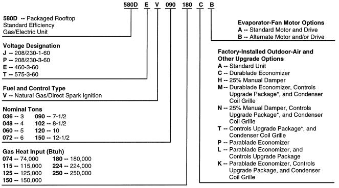
MODEL NUMBER NOMENCLATURE
580D036-150 MODELS ONLY
*Contains high pressure, (loss-of-charge) low-pressure, and freeze protection cutout switches.
NOTE: The example model number 580DEV090180CB designates a 71¤2 ton 460-3-60 volt gas/electric rooftop unit with 180,000 Btuh natural gas heat, Durablade economizer, and alternate drive.
4
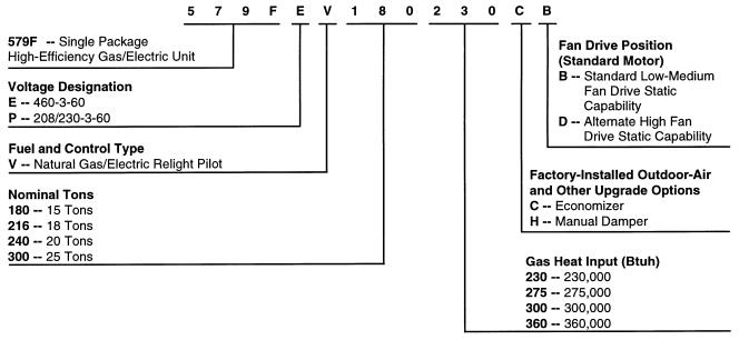
MODEL NUMBER NOMENCLATURE (cont)
579F180-300 MODELS ONLY
NOTE: The example model number 579FEV180230CB designates a 15-ton 460-3-60 volt gas/electric rooftop unit with 230,000 Btuh natural gas heat input, economizer, and the standard low-medium fan drive static capability.
5

ARI* CAPACITY RATINGS
|
|
|
|
NOMINAL |
|
|
STANDARD |
|
NET COOLING |
|
TOTAL |
|
|
SEER² |
|
SOUND |
|||
UNIT 580D |
|
|
|
|
CAPACITY |
|
|
|
|
|
|
|
RATING |
||||||
|
|
|
|
TONS |
|
|
CFM |
|
(Btuh) |
|
|
kW |
|
Belt Drive |
|
Direct Drive |
|
(Bels) |
|
|
|
|
|
|
|
|
|
|
|
|
|
|
|
|
|||||
|
036 |
|
|
3 |
|
|
1200 |
35,000 |
|
4.0 |
|
10.0 |
9.7 |
8.2 |
|||||
|
048 |
|
|
4 |
|
|
1600 |
47,000 |
|
5.5 |
|
10.0 |
9.7 |
8.2 |
|||||
|
060 |
|
|
5 |
|
|
2000 |
57,000 |
|
6.7 |
|
10.0 |
9.7 |
8.2 |
|||||
|
|
|
|
|
|
|
|
|
|
|
|
|
|
|
|
|
|
|
|
|
|
|
|
|
|
|
|
|
|
|
|
|
|
|
|
|
|
|
|
|
|
|
|
NOMINAL |
|
STANDARD |
|
NET COOLING |
|
TOTAL |
|
|
|
SOUND |
|
|
|||
|
UNIT |
|
|
|
|
CAPACITY |
|
|
EER |
|
RATING |
|
IPLV |
||||||
|
|
TONS |
|
CFM |
|
|
kW |
|
|
|
|||||||||
|
|
|
|
|
|
(Btuh) |
|
|
|
|
(Bels) |
|
|
||||||
|
|
|
|
|
|
|
|
|
|
|
|
|
|
|
|
|
|||
|
580D072 |
|
6 |
|
|
2100 |
|
72,000 |
|
|
8.0 |
|
9.0 |
|
8.2 |
|
** |
||
|
580D090 |
|
71¤2 |
|
|
2800 |
|
85,000 |
|
|
9.6 |
|
8.9 |
|
8.6 |
|
9.35 |
||
|
580D102 |
|
81¤2 |
|
|
3000 |
|
99,000 |
|
|
11.0 |
|
9.0 |
|
8.6 |
|
9.00 |
||
|
580D120 |
|
10 |
|
|
4000 |
|
117,000 |
|
|
13.0 |
|
9.0 |
|
8.8 |
|
9.35 |
||
|
580D150 |
|
121¤2 |
|
|
4500 |
|
145,000 |
|
|
16.1 |
|
9.0 |
|
8.8 |
|
9.20 |
||
|
579F180 |
|
15 |
|
|
5250 |
|
178,000 |
|
|
20.7 |
|
8.6 |
|
8.8 |
|
10.70 |
||
|
579F216 |
|
18 |
|
|
6000 |
|
190,000 |
|
|
21.3 |
|
8.9 |
|
9.0 |
|
9.20 |
||
|
579F240 |
|
20 |
|
|
6200 |
|
222,000 |
|
|
25.5 |
|
8.6 |
|
9.5 |
|
8.80 |
||
|
579F300 |
|
25 |
|
|
7200 |
|
268,000 |
|
|
31.4 |
|
8.5 |
|
9.5 |
|
8.40 |
||
|
|
|
LEGEND |
|
|
|
|
|
|
|
|
|
|
|
|
|
|||
Bels |
Ð Sound Levels (1 bel = 10 decibels) |
|
|
|
|
|
|
|
|
|
|
|
|
||||||
db |
Ð Dry Bulb |
|
|
|
|
|
|
|
|
|
|
|
|
|
|
|
|
||
EER |
Ð Energy Efficiency Ratio |
|
|
|
|
|
|
|
|
|
|
|
|
|
|||||
IPLV |
Ð Integrated Part-Load Values |
|
|
|
|
|
|
|
|
|
|
|
|
|
|||||
SEER Ð Seasonal Energy Efficiency Ratio |
|
|
|
|
|
|
|
|
|
|
|
|
|||||||
wb |
Ð Wet Bulb |
|
|
|
|
|
|
|
|
|
|
|
|
|
|
|
|
||
*Air Conditioning and Refrigeration Institute.
²Applies only to units with capacity of 65,000 Btuh or less. **The IPLV applies only to two-stage cooling units.
NOTES:
1.Rated in accordance with ARI Standards 210/240-89 (for sizes 036-120) or 360-89 (for sizes 150-240) and 270-89.
2.The 579F300 is beyond the scope of the ARI certi®cation program.
3.ARI ratings are net values, re¯ecting the effects of circulating fan heat.
4.Ratings are based on:
Cooling Standard: 80 F db, 67 F wb indoor entering-air temperature and 95 F db air entering outdoor unit. IPLV Standard: 80 F db, 67 F wb indoor entering-air temperature and 80 F db outdoor entering-air temperature.
6
ARI* CAPACITY RATINGS (cont)
HEATING CAPACITIES AND EFFICIENCIES Ð 580D036-150
|
HEATING INPUT |
|
TEMPERATURE |
|
STEADY-STATE |
CALIFORNIA |
||
|
OUTPUT CAPACITY |
AFUE |
SEASONAL |
|||||
UNIT 580D |
(Btuh) |
RISE |
EFFICIENCY |
|||||
(Btuh) |
(%) |
EFFICIENCY |
||||||
|
Stage 2/Stage 1 |
(F) |
(%) |
|||||
|
|
|
(%) |
|||||
|
|
|
|
|
|
|
||
036 074 |
Ð/ |
72,000 |
59,200 |
25-55 |
80.0 |
80.0 |
77.2 |
|
036 115 |
115,000/ |
82,000 |
92,000 |
55-85 |
80.0 |
80.0 |
76.7 |
|
048 074 |
Ð/ |
72,000 |
59,200 |
25-55 |
80.0 |
80.0 |
77.2 |
|
048 115 |
Ð/115,000 |
92,000 |
35-65 |
80.0 |
80.0 |
77.1 |
||
048 150 |
150,000/120,000 |
120,000 |
50-80 |
80.0 |
80.0 |
76.9 |
||
060 074 |
Ð/ |
72,000 |
59,200 |
25-55 |
80.0 |
80.0 |
77.2 |
|
060 115 |
Ð/115,000 |
92,000 |
35-65 |
80.0 |
80.0 |
77.1 |
||
060 150 |
150,000/120,000 |
120,000 |
50-80 |
80.0 |
80.0 |
76.9 |
||
072 074 |
Ð/ |
72,000 |
59,200 |
25-55 |
80.0 |
80.0 |
77.2 |
|
072 115 |
Ð/115,000 |
92,000 |
35-65 |
80.0 |
80.0 |
77.1 |
||
072 150 |
150,000/120,000 |
120,000 |
50-80 |
80.0 |
80.0 |
76.9 |
||
090 125 |
Ð/125,000 |
100,000 |
20-50 |
80.0 |
80.0 |
75.8 |
||
090 180 |
180,000/120,000 |
144,000 |
35-65 |
80.0 |
80.0 |
77.1 |
||
090 224 |
224,000/180,000 |
179,200 |
45-75 |
80.0 |
80.0 |
77.1 |
||
102 125 |
Ð/125,000 |
100,000 |
20-50 |
80.0 |
80.0 |
75.8 |
||
102 184 |
180,000/120,000 |
144,000 |
35-65 |
80.0 |
80.0 |
77.1 |
||
102 224 |
224,000/180,000 |
179,200 |
45-75 |
80.0 |
80.0 |
77.1 |
||
120 180 |
180,000/120,000 |
144,000 |
35-65 |
80.0 |
80.0 |
77.1 |
||
120 224 |
224,000/180,000 |
179,200 |
35-65 |
80.0 |
80.0 |
77.1 |
||
120 250 |
250,000/200,000 |
200,000 |
40-70 |
80.0 |
80.0 |
76.4 |
||
150 224 |
224,000/180,000 |
179,200 |
35-65 |
80.0 |
80.0 |
77.1 |
||
150 250 |
250,000/200,000 |
200,000 |
40-70 |
80.0 |
80.0 |
76.4 |
||
LEGEND
AFUE Ð Annual Fuel Utilization Efficiency
NOTE: NOx levels are 40 nanograms/joule or less with the accessory NOx reduction kit (sizes 036-060).
HEATING CAPACITIES AND EFFICIENCIES Ð 579F180-300
|
HEATING INPUT |
OUTPUT CAPACITY |
TEMPERATURE |
STEADY-STATE |
MINIMUM |
|
UNIT 579F |
(Btuh) |
RISE |
EFFICIENCY |
HEATING |
||
(Btuh) |
||||||
|
Stage 2/Stage 1* |
(F) |
(%) |
CFM |
||
|
|
|||||
180 230 |
230,000/172,000 |
186,000 |
15-45 |
81.0 |
3800 |
|
180 300 |
300,000/225,000 |
243,000 |
30-60 |
81.0 |
3800 |
|
216 275 |
275,000/206,000 |
223,000 |
15-45 |
81.0 |
4750 |
|
216 360 |
360,000/270,000 |
292,000 |
20-50 |
81.0 |
5450 |
|
240 275 |
275,000/206,000 |
223,000 |
15-45 |
81.0 |
4750 |
|
240 360 |
360,000/270,000 |
292,000 |
20-50 |
81.0 |
5450 |
|
300 275 |
275,000/206,000 |
223,000 |
15-45 |
81.0 |
4750 |
|
300 360 |
360,000/270,000 |
292,000 |
20-50 |
81.0 |
5450 |
*All units are 2-stage heat.
NOTE: Minimum allowable temperature of mixed-air entering the heat exchanger during ®rst-stage heating is 45 F. There is no minimum mixed-air temperature limitation during second-stage heating. For entering-air temperatures below 45 F both stages of heat must be energized together to minimize condensation issues and to ensure proper unit operation.
7

PHYSICAL DATA Ð 580D036-072
UNIT SIZE 580D |
|
036 |
|
048 |
|
060 |
072 |
NOMINAL CAPACITY (tons) |
|
3 |
|
4 |
|
5 |
6 |
OPERATING WEIGHT (lb) |
|
|
|
|
|
|
|
Unit |
|
|
|
|
|
|
|
Al/Al* |
|
460 |
|
470 |
|
490 |
565 |
Al/Cu* |
|
465 |
|
476 |
|
497 |
576 |
Cu/Cu* |
|
468 |
|
482 |
|
505 |
587 |
Economizer |
|
|
|
|
|
|
|
Durablade |
|
34 |
|
34 |
|
34 |
34 |
Parablade |
|
42 |
|
42 |
|
42 |
42 |
Roof Curb² |
|
115 |
|
115 |
|
115 |
115 |
COMPRESSOR |
|
|
|
|
Hermetic |
|
|
Quantity |
|
1 |
|
1 |
1 |
1 |
|
No. Cylinders (per Circuit) |
|
2 |
|
2 |
2 |
2 |
|
Oil (oz) |
|
50 |
|
50 |
50 |
54 |
|
REFRIGERANT TYPE |
|
|
|
|
R-22 |
|
|
Expansion Device |
|
|
|
Acutrol™ Feed Device |
|
||
Operating Charge (lb-oz) |
|
|
|
|
|
|
|
Circuit 1 |
|
3-6 |
|
4-11 |
|
5-13 |
7-8 |
Circuit 2 |
|
Ð |
|
Ð |
|
Ð |
Ð |
CONDENSER COIL |
|
|
Enhanced Copper Tubes, |
Aluminum Lanced |
Fins |
||
Rows...Fins/in. |
|
1...17 |
1...17 |
|
1...17 |
2...17 |
|
Total Face Area (sq ft) |
|
7.36 |
11.39 |
|
13.19 |
10.42 |
|
CONDENSER FAN |
|
|
|
Propeller |
Type |
|
|
Nominal Cfm |
|
3500 |
4000 |
|
4000 |
4000 |
|
Quantity...Diameter (in.) |
|
1...22.0 |
1...22.0 |
|
1...22.0 |
1...22.0 |
|
Motor Hp...Rpm |
|
1¤4...1100 |
1¤4...1100 |
|
1¤4...1100 |
1¤4...1100 |
|
Watts Input (Total) |
|
325 |
325 |
|
325 |
325 |
|
EVAPORATOR COIL |
|
Enhanced Copper Tubes, |
Aluminum Double-Wavy Fins |
||||
Rows...Fins/in. |
|
2...15 |
2...15 |
|
3...15 |
4...15 |
|
Total Face Area (sq ft) |
|
4.17 |
5.5 |
|
5.5 |
5.5 |
|
EVAPORATOR FAN |
|
|
|
Centrifugal |
Type |
|
|
Quantity...Size (in.) |
Std |
1...10 x 10 |
|
1...10 x 10 |
|
1...11 x 10 |
1...10 x 10 |
|
Alt |
1...10 x 10 |
|
1...10 x 10 |
|
1...10 x 10 |
Ð |
Type Drive |
Std |
Direct |
|
Direct |
|
Direct |
Belt |
Nominal Cfm |
Alt |
Belt |
|
Belt |
|
Belt |
Ð |
|
1200 |
1600 |
|
2000 |
2400 |
||
Motor Hp |
Std |
Ð |
Ð |
|
Ð |
Ð |
|
|
Alt |
Ð |
Ð |
|
Ð |
Ð |
|
Maximum Continuous Bhp |
Std |
.34 |
.75 |
|
1.20 |
2.40 |
|
|
Alt |
1.00 |
1.00 |
|
1.80 |
Ð |
|
Motor Frame Size |
Std |
48 |
48 |
|
48 |
56 |
|
|
Alt |
48 |
48 |
|
48 |
Ð |
|
Nominal Rpm High/Low |
Std |
860/800 |
1075/970 |
|
1075/970 |
Ð |
|
|
Alt |
Ð |
Ð |
|
Ð |
Ð |
|
Fan Rpm Range |
Std |
Ð |
Ð |
|
Ð |
1070-1460 |
|
Motor Bearing Type |
Alt |
760-1000 |
835-1185 |
|
900-1300 |
Ð |
|
|
Ball |
|
Ball |
|
Ball |
Ball |
|
Maximum Allowable Rpm |
|
2100 |
2100 |
|
2100 |
2100 |
|
Motor Pulley Pitch Diameter Min/Max (in.) |
Std |
Ð |
Ð |
|
Ð |
2.8/3.8 |
|
|
Alt |
1.9/2.9 |
1.9/2.9 |
|
2.4/3.4 |
Ð |
|
Nominal Motor Shaft Diameter (in.) |
Std |
1¤2 |
1¤2 |
|
1¤2 |
5¤8 |
|
|
Alt |
1¤2 |
1¤2 |
|
1¤2 |
Ð |
|
Fan Pulley Pitch Diameter (in.) |
Std |
Ð |
Ð |
|
Ð |
4.5 |
|
Nominal Fan Shaft Diameter (in.) |
Alt |
4.5 |
4.0 |
|
4.5 |
Ð |
|
|
Ð |
Ð |
|
Ð |
Ð |
||
Belt, Quantity...Type...Length (in.) |
Std |
Ð |
Ð |
|
Ð |
1...A...40 |
|
|
Alt |
1...A...34 |
|
1...A...34 |
|
1...A...39 |
Ð |
Pulley Center Line Distance (in.) |
Std |
Ð |
Ð |
|
Ð |
14.7-15.5 |
|
|
Alt |
10.0-12.4 |
10.0-12.4 |
|
14.7-15.5 |
Ð |
|
Speed Change per Full Turn of |
Std |
Ð |
Ð |
|
Ð |
80 |
|
Movable Pulley Flange (rpm) |
Alt |
48 |
70 |
|
80 |
Ð |
|
Movable Pulley Maximum Full Turns |
Std |
Ð |
Ð |
|
Ð |
5 |
|
From Closed Position |
Alt |
5 |
5 |
|
5 |
Ð |
|
Factory Setting |
Std |
Ð |
Ð |
|
Ð |
3 |
|
|
Alt |
3 |
3 |
|
3 |
Ð |
|
Factory Speed Setting (rpm) |
Std |
Ð |
Ð |
|
Ð |
1225 |
|
Fan Shaft Diameter at Pulley (in.) |
Alt |
856 |
975 |
|
1060 |
Ð |
|
|
1¤2 |
1¤2 |
|
1¤2 |
1¤2 |
||
|
LEGEND |
Al |
Ð Aluminum |
Bhp |
Ð Brake Horsepower |
Cu |
Ð Copper |
*Evaporator coil ®n material/condenser coil ®n material. Contact your local representative for details about coated ®ns.
²Weight of 14-in. roof curb.
**Rollout switch lockout is manually reset by interrupting power to unit or resetting thermostat.
²²Requires an optional or accessory Controls Upgrade Kit.
NOTE: The 580D036-150 units have a loss-of-charge/low-pressure switch (accessory or option) located in the liquid line.
8
PHYSICAL DATA Ð 580D036-072 (cont)
|
|
036 |
048 |
|
060 |
072 |
UNIT SIZE 580D |
|
MEDIUM/ |
LOW/MEDIUM/ |
|
LOW/MEDIUM/ |
LOW/MEDIUM/ |
|
|
HIGH HEAT |
HIGH HEAT |
|
HIGH HEAT |
HIGH HEAT |
FURNACE SECTION |
|
|
|
|
|
|
Rollout Switch Cutout |
|
|
|
|
|
|
Temp (F)** |
|
195 |
195 |
|
195 |
195 |
Burner Ori®ce Diameter |
|
|
|
|
|
|
(in. ...drill size) |
|
|
|
|
|
|
Natural Gas |
Std |
.113...33 |
.113...33/.113...33/.129...30 |
|
.113...33/.113...33/.129...30 |
.113...33/.113...33/.129...30 |
Liquid Propane |
Alt |
.089...43 |
.089...43/.089...43/.102...38 |
|
.089...43/.089...43/.102...38 |
.089...43/.089...43/.102...38 |
Pilot Ori®ce Diameter |
|
|
|
|
|
|
(Quantity) in. ...drill size |
|
|
|
|
|
|
Natural Gas |
Std |
Ð |
Ð |
|
Ð |
Ð |
Liquid Propane |
Alt |
Ð |
Ð |
|
Ð |
Ð |
Thermostat Heat Anticipator |
|
|
|
|
|
|
Setting (amps) |
|
|
|
|
|
|
208/230 v and 575 v Stage 1 |
|
.14 |
.14 |
|
.14 |
.14 |
Stage 2 |
|
.14 |
.14 |
|
.14 |
.14 |
460 v Stage 1 |
|
.14 |
.14 |
|
.14 |
.14 |
Stage 2 |
|
.14 |
.14 |
|
.14 |
.14 |
Gas Input (Btuh) Stage 1 |
|
72,000/82,000 |
72,000/115,000/120,000 |
|
72,000/115,000/120,000 |
72,000/115,000/120,000 |
Stage 2 |
|
Ð/115,000 |
Ð/Ð/150,000 |
|
Ð/Ð/150,000 |
Ð/Ð/150,000 |
Efficiency (Steady |
|
|
|
|
|
|
State) (%) |
|
80 |
80 |
|
80 |
80 |
Temperature Rise Range |
|
25-55/55-85 |
25-55/35-65/50-80 |
|
25-55/35-65/50-80 |
25-55/35-65/50-80 |
Manifold Pressure (in. wg) |
|
|
|
|
|
|
Natural Gas |
Std |
3.5 |
3.5 |
|
3.5 |
3.5 |
Liquid Propane |
Alt |
3.5 |
3.5 |
|
3.5 |
3.5 |
Gas Valve Quantity |
|
1 |
1 |
|
1 |
1 |
Gas Valve Pressure Range |
|
|
|
|
|
|
Psig |
|
0.180-0.487 |
0.180-0.487 |
|
0.180-0.487 |
0.180-0.487 |
in. wg |
|
5.0-13.5 |
5.0-13.5 |
|
5.0-13.5 |
5.0-13.5 |
Field Gas Connection |
|
|
|
|
|
|
Size (in.) |
|
1¤2 |
1¤2 |
|
1¤2 |
1¤2 |
HIGH-PRESSURE SWITCH (psig)²² |
|
|
|
|
|
|
Standard Compressor |
|
|
450 ± 50 |
|
|
500 ± 50 |
Internal Relief (Differential) |
|
|
|
|
|
|
Cutout |
|
|
428 |
|
|
428 |
Reset (Auto.) |
|
|
320 |
|
|
320 |
LOW-PRESSURE SWITCH (psig)²² |
|
|
|
|
|
|
Cutout |
|
|
|
7 ± 3 |
|
|
Reset (Auto.) |
|
|
|
22 ± 7 |
|
|
FREEZE PROTECTION |
|
|
|
|
|
|
THERMOSTAT (F)** |
|
|
|
|
|
|
Opens |
|
|
|
30 ± 5 |
|
|
Closes |
|
|
|
45 ± 5 |
|
|
OUTDOOR-AIR INLET SCREENS |
|
|
|
|
Cleanable |
|
Quantity...Size (in.) |
|
|
|
1...20 x 24 x 1 |
|
|
RETURN-AIR FILTERS |
|
|
|
|
Throwaway |
|
Quantity...Size (in.) |
|
|
|
2...16 x 25 x 2 |
|
|
|
|
|
|
|
|
|
|
LEGEND |
Al |
Ð Aluminum |
Bhp |
Ð Brake Horsepower |
Cu |
Ð Copper |
*Evaporator coil ®n material/condenser coil ®n material. Contact your local representative for details about coated ®ns.
²Weight of 14-in. roof curb.
**Rollout switch lockout is manually reset by interrupting power to unit or resetting thermostat.
²²Requires an optional or accessory Controls Upgrade Kit.
NOTE: The 580D036-150 units have a loss-of-charge/low-pressure switch (accessory or option) located in the liquid line.
9

PHYSICAL DATA Ð 580D090-150
UNIT SIZE 580D |
|
090 |
102 |
|
120 |
150 |
NOMINAL CAPACITY (tons) |
|
71¤2 |
81¤2 |
|
10 |
121¤2 |
OPERATING WEIGHT (lb) |
|
|
|
|
|
|
Unit |
|
|
|
|
|
|
Al/Al* |
|
870 |
880 |
|
1035 |
1050 |
Al/Cu* |
|
881 |
896 |
|
1057 |
1077 |
Cu/Cu* |
|
893 |
907 |
|
1080 |
1100 |
Economizer |
|
|
|
|
|
|
Durablade |
|
44 |
44 |
|
44 |
44 |
Parablade |
|
62 |
62 |
|
62 |
62 |
Roof Curb² |
|
143 |
143 |
|
143 |
143 |
COMPRESSOR |
|
|
Hermetic |
|
||
Quantity |
|
2 |
2 |
2 |
2 |
|
No. Cylinders (per Circuit) |
|
2 |
2 |
2 |
2 |
|
Oil (oz) |
|
50 ea |
50 ea |
|
50 ea |
54 ea |
REFRIGERANT TYPE |
|
|
|
R-22 |
|
|
Expansion Device |
|
|
Acutrol™ Feed Device |
|
||
Operating Charge (lb-oz) |
|
|
|
|
|
|
Circuit 1 |
|
4-13 |
6-14 |
|
5-13 |
8-10 |
Circuit 2 |
|
4-14 |
6- 3 |
|
5-14 |
8- 8 |
CONDENSER COIL |
|
Enhanced Copper Tubes, |
Aluminum Lanced |
Fins |
||
Rows...Fins/in. |
|
1...17 |
2...17 |
|
2...17 |
2...17 |
Total Face Area (sq ft) |
|
20.50 |
18.00 |
|
17.42 |
25.00 |
CONDENSER FAN |
|
|
Propeller |
Type |
|
|
Nominal Cfm |
|
6500 |
6500 |
|
7000 |
7000 |
Quantity...Diameter (in.) |
|
2...22 |
2...22 |
|
2...22 |
2...22 |
Motor Hp...Rpm |
|
1¤4...1100 |
1¤4...1100 |
|
1¤4...1100 |
1¤4...1100 |
Watts Input (Total) |
|
600 |
600 |
|
600 |
600 |
EVAPORATOR COIL |
|
Enhanced Copper Tubes, |
Aluminum Double-Wavy Fins |
|||
Rows...Fins/in. |
|
3...15 |
3...15 |
|
3...15 |
4...15 |
Total Face Area (sq ft) |
|
8.0 |
8.0 |
|
10.0 |
11.1 |
EVAPORATOR FAN |
|
|
Centrifugal |
Type |
|
|
Quantity...Size (in.) |
Std |
1...15 x 15 |
1...15 x 15 |
|
1...15 x 15 |
1...15 x 15 |
|
Alt |
1...15 x 15 |
Ð |
|
1...15 x 15 |
1...15 x 15 |
Type Drive |
Std |
Belt |
Belt |
|
Belt |
Belt |
Nominal Cfm |
Alt |
Belt |
Ð |
|
Belt |
Belt |
|
3000 |
3400 |
|
4000 |
5000 |
|
Motor Hp |
Std |
Ð |
Ð |
|
Ð |
Ð |
|
Alt |
Ð |
Ð |
|
Ð |
Ð |
Maximum Continuous Bhp |
Std |
2.40 |
2.40 |
|
2.40 |
4.20 |
|
Alt |
Ð |
Ð |
|
2.90 |
5.25 |
Motor Frame Size |
Std |
56 |
56 |
|
56 |
56 |
Nominal Rpm High/Low |
Alt |
Ð |
Ð |
|
56 |
56 |
|
Ð |
Ð |
|
Ð |
Ð |
|
Fan Rpm Range |
Std |
590-840 |
685-935 |
|
685-935 |
860-1080 |
Motor Bearing Type |
Alt |
685-935 |
Ð |
|
835-1085 |
900-1260 |
|
Ball |
Ball |
|
Ball |
Ball |
|
Maximum Allowable Rpm |
|
2100 |
2100 |
|
2100 |
2100 |
Motor Pulley Pitch Diameter Min/Max (in.) |
Std |
2.4/3.4 |
2.8/3.8 |
|
2.8/3.8 |
4.0/5.0 |
|
Alt |
2.8/3.8 |
Ð |
|
3.4/4.4 |
3.1/4.1 |
Nominal Motor Shaft Diameter (in.) |
Std |
5¤8 |
5¤8 |
|
5¤8 |
7¤8 |
|
Alt |
Ð |
Ð |
|
7¤8 |
7¤8 |
Fan Pulley Pitch Diameter (in.) |
Std |
7.0 |
7.0 |
|
7.0 |
8.0 |
Nominal Fan Shaft Diameter (in.) |
Alt |
7.0 |
Ð |
|
7.0 |
5.9 |
|
Ð |
Ð |
|
Ð |
Ð |
|
Belt, Quantity...Type...Length (in.) |
Std |
1...A...49 |
1...A...49 |
|
1...A...49 |
1...A...52 |
|
Alt |
1...A...49 |
Ð |
|
1...A...49 |
1...BX...46 |
Pulley Center Line Distance (in.) |
Std |
16.75-19.25 |
16.75-19.25 |
|
15.85-17.50 |
15.85-17.50 |
|
Alt |
16.75-19.25 |
Ð |
|
15.85-17.50 |
15.85-17.50 |
Speed Change per Full Turn of |
Std |
50 |
50 |
|
50 |
44 |
Movable Pulley Flange (rpm) |
Alt |
50 |
Ð |
|
50 |
50 |
Movable Pulley Maximum Full Turns |
Std |
5 |
5 |
|
5 |
5 |
From Closed Position |
Alt |
5 |
Ð |
|
5 |
6 |
Factory Setting |
Std |
5 |
5 |
|
5 |
5 |
|
Alt |
5 |
Ð |
|
5 |
5 |
Factory Speed Setting (rpm) |
Std |
590 |
685 |
|
685 |
860 |
Fan Shaft Diameter at Pulley (in.) |
Alt |
685 |
Ð |
|
835 |
960 |
|
1 |
1 |
|
1 |
1 |
|
|
LEGEND |
Al |
Ð Aluminum |
Bhp |
Ð Brake Horsepower |
Cu |
Ð Copper |
*Evaporator coil ®n material/condenser coil ®n material. Contact your local representative for details about coated ®ns.
²Weight of 14-in. roof curb.
**Rollout switch lockout is manually reset by interrupting power to unit or resetting thermostat.
²²Requires an optional or accessory Controls Upgrade Kit.
NOTE: The 580D036-150 units have a loss-of-charge/low-pressure switch (accessory or option) located in the liquid line.
10
PHYSICAL DATA Ð 580D090-150 (cont)
|
|
090 |
102 |
120 |
150 |
UNIT SIZE 580D |
|
LOW/MEDIUM/ |
LOW/MEDIUM/ |
LOW/MEDIUM/ |
LOW/ |
|
|
HIGH HEAT |
HIHG HEAT |
HIGH HEAT |
MEDIUM HEAT |
FURNACE SECTION |
|
|
|
|
|
Rollout Switch Cutout |
|
|
|
|
|
Temp (F)²² |
|
195 |
195 |
195 |
195 |
Burner Ori®ce Diameter |
|
|
|
|
|
(in. ...drill size) |
|
|
|
|
|
Natural Gas |
Std |
.120...31 |
.120...31 |
.120...31/.120...31/.129...30 |
.120...31/.129...30 |
Liquid Propane |
Alt |
.096...41 |
.096...41 |
.096...41/.096...41/.102...38 |
.096...41/.102...38 |
Pilot Ori®ce Diameter |
|
|
|
|
|
(Quantity) in. ...drill size |
|
|
|
|
|
Natural Gas |
Std |
Ð |
Ð |
Ð |
Ð |
Liquid Propane |
Alt |
Ð |
Ð |
Ð |
Ð |
Thermostat Heat Anticipator |
|
|
|
|
|
Setting (amps) |
|
|
|
|
|
208/230 v and 575 v Stage 1 |
|
.14 |
.14 |
.14 |
.14 |
Stage 2 |
|
.20 |
.20 |
.20 |
.20 |
460 v Stage 1 |
|
.14 |
.14 |
.14 |
.14 |
Stage 2 |
|
.20 |
.20 |
.20 |
.20 |
Gas Input (Btuh) Stage 1 |
|
125,000/120,000/180,000 |
125,000/120,000/180,000 |
120,000/180,000/200,000 |
180,000/200,000 |
Stage 2 |
|
Ð/180,000/224,000 |
Ð/180,000/224,000 |
180,000/224,000/250,000 |
224,000/250,000 |
Efficiency (Steady |
|
|
|
|
|
State) (%) |
|
80 |
80 |
80 |
80 |
Temperature Rise Range |
|
20-50/35-65/45-75 |
20-50/35-65/45-75 |
35-65/35-65/40-70 |
35-65/40-70 |
Manifold Pressure (in. wg) |
|
|
|
|
|
Natural Gas |
Std |
3.5 |
3.5 |
3.5 |
3.5 |
Liquid Propane |
Alt |
3.5 |
3.5 |
3.5 |
3.5 |
Gas Valve Quantity |
|
1 |
1 |
1 |
1 |
Gas Valve Pressure Range |
|
|
|
|
|
Psig |
|
0.180-0.487 |
0.180-0.487 |
0.180-0.487 |
0.180-0.487 |
in. wg |
|
5.0-13.5 |
5.0-13.5 |
5.0-13.5 |
5.0-13.5 |
Field Gas Connection |
|
|
|
|
|
Size (in.) |
|
1¤2/3¤4/3¤4 |
1¤2/3¤4/3¤4 |
3¤4/3¤4/3¤4 |
3¤4/3¤4 |
HIGH-PRESSURE SWITCH (psig)²² |
|
|
|
|
|
Standard Compressor |
|
|
450 ± 50 |
|
500 ± 50 |
Internal Relief (Differential) |
|
|
|
|
|
Cutout |
|
|
428 |
|
428 |
Reset (Auto.) |
|
|
320 |
|
320 |
LOW-PRESSURE SWITCH (psig)²² |
|
|
|
|
|
Cutout |
|
|
7 ± 3 |
|
|
Reset (Auto.) |
|
|
22 ± 7 |
|
|
FREEZE PROTECTION |
|
|
|
|
|
THERMOSTAT (F)** |
|
|
|
|
|
Opens |
|
|
30 ± 5 |
|
|
Closes |
|
|
45 ± 5 |
|
|
OUTDOOR-AIR INLET SCREENS |
|
|
Cleanable |
|
|
Quantity...Size (in.) |
|
|
1...20 x 25 x 1 |
|
|
|
|
|
1...16 x 25 x 1 |
|
|
RETURN-AIR FILTERS |
|
|
Throwaway |
|
|
Quantity...Size (in.) |
|
4...16 x 20 x 2 |
4...16 x 20 x 2 |
4...20 x 20 x 2 |
4...20 x 20 x 2 |
|
|
|
|
|
|
|
LEGEND |
Al |
Ð Aluminum |
Bhp |
Ð Brake Horsepower |
Cu |
Ð Copper |
*Evaporator coil ®n material/condenser coil ®n material. Contact your local representative for details about coated ®ns.
²Weight of 14-in. roof curb.
**Rollout switch lockout is manually reset by interrupting power to unit or resetting thermostat.
²²Requires an optional or accessory Controls Upgrade Kit.
NOTE: The 580D036-150 units have a loss-of-charge/low-pressure switch (accessory or option) located in the liquid line.
11

PHYSICAL DATA Ð 579F180-300
UNIT SIZE 579F |
|
180 |
216 |
|
240 |
300 |
NOMINAL CAPACITY (tons) |
|
15 |
18 |
|
20 |
25 |
|
|
|
|
|
|
|
OPERATING WEIGHT (lb) |
|
|
|
|
|
|
Unit |
|
|
|
|
|
|
Al/Al* |
|
1650 |
2150 |
|
2200 |
2250 |
Economizer |
|
110 |
110 |
|
110 |
110 |
Roof Curb² |
|
200 |
200 |
|
200 |
200 |
COMPRESSOR |
|
|
Semi- |
Hermetic |
|
|
Model No. ...Quantity |
|
06D-537...1 (6) |
06D-824...1 (6) |
|
06D-824...2 (6) |
06D-328...2 (6) |
(Number of Cylinders) |
|
06D-818...1 (4) |
|
|||
|
|
|
|
|
||
Oil (oz) |
|
115 |
88,115 |
|
115 ea |
128 ea |
No. of Cylinders (per circuit) |
|
6 |
6 |
|
6 |
6 |
Cooling Capacity Stages (%) |
|
0, 66, 100 |
0, 57, 100 |
|
0, 50, 100 |
0, 50, 100 |
REFRIGERANT TYPE |
|
|
|
R |
-22 |
|
Expansion Device |
|
TXV |
Acutrol™ Refrigerant Metering Device |
|||
Operating Charge (lb-oz) |
|
|
|
|
|
|
Circuit 1** |
|
19-4 |
13-4 |
|
12-13 |
16-12 |
Circuit 2 |
|
Ð |
11-0 |
|
12-13 |
15-12 |
CONDENSER COIL |
|
3¤8-in. Enhanced Copper Tubes, |
Aluminum Lanced or |
Copper Fins |
||
Rows...Fins/in. |
|
2...17 |
3...15 |
|
3...15 |
4...15 |
Total Face Area (sq ft) |
|
22.2 |
22.2 |
|
22.2 |
22.2 |
CONDENSER FAN |
|
|
Propeller |
Type |
|
|
Nominal Cfm |
|
10,500 |
10,500 |
|
14,200 |
14,200 |
Quantity...Diameter (in.) |
|
3...22 |
3...22 |
|
2...30 |
2...30 |
Motor Hp...Rpm |
|
1¤2...1050 |
1¤2...1050 |
|
1...1075 |
1...1075 |
Watts Input (Total) |
|
1100 |
1100 |
|
3400 |
3400 |
EVAPORATOR COIL |
|
3¤8-in. Enhanced Copper Tubes, Aluminum or Copper Plate |
Fins, Face Split |
|||
Rows...Fins/in. |
|
2...17 |
3...17 |
4...15 |
4...15 |
|
Total Face Area (sq ft) |
|
17.9 |
17.9 |
17.9 |
17.9 |
|
EVAPORATOR FAN |
|
|
Centrifugal Type |
|
||
Quantity...Size (in.) |
|
2...10 x 10 |
2...12 x 12 |
|
2...12 x 12 |
2...12 x 12 |
Type Drive |
|
Belt |
Belt |
|
Belt |
Belt |
Nominal Cfm |
|
6000 |
7200 |
8000 |
10,000 |
|
Motor Hp |
|
3.7 |
5 |
71¤2 |
10 |
|
Motor Nominal rpm |
|
1725 |
1745 |
1745 |
1740 |
|
Maximum Continuous Bhp |
|
4.25 |
5.90 |
|
8.7 [208/230 v] |
10.2 [208/230 v] |
|
|
9.5 [460 v] |
11.8 [460 v] |
|||
Motor Frame Size |
|
|
|
|
||
|
56H |
184T |
|
213T |
215T |
|
Nominal Rpm High/Low |
|
Ð |
Ð |
Ð |
Ð |
|
Fan Rpm Range |
Low-Medium Static |
891-1179 |
817-1038 |
1002-1225 |
1066-1283 |
|
Motor Bearing Type |
High Static |
1227-1550 |
994-1197 |
1193-1458 |
1332-1550 |
|
|
Ball |
Ball |
|
Ball |
Ball |
|
Maximum Allowable Rpm |
|
1550 |
1550 |
1550 |
1550 |
|
Motor Pulley Pitch Diameter |
Low-Medium Static |
3.1-4.1 |
3.7-4.7 |
5.4-6.6 |
4.9-5.9 |
|
Min/Max (in.) |
High Static |
3.7-4.7 |
4.9-5.9 |
5.4-6.6 |
4.9-5.9 |
|
Nominal Motor Shaft Diameter (in.) |
|
7¤8 |
11¤8 |
13¤8 |
13¤8 |
|
Fan Pulley Pitch Diameter (in.) |
Low-Medium Static |
6.0 |
7.9 |
9.4 |
8.0 |
|
Nominal Fan Shaft Diameter (in.) |
High Static |
5.2 |
8.6 |
7.9 |
6.4 |
|
|
13¤16 |
17¤16 |
17¤16 |
17¤16 |
||
Belt, Quantity...Type...Length (in.) |
Low-Medium Static |
1...BX...42 |
1...BX...46 |
|
1...BX...53 |
2...BX...50 |
Pulley Center Line Distance (in.) |
High Static |
1...BX...42 |
1...BX...50 |
|
1...BX...50 |
2...BX...47 |
|
13.5-15.5 |
13.3-14.8 |
14.6-15.4 |
14.6-15.4 |
||
Speed Change per Full Turn of |
Low-Medium Static |
48 |
37 |
37 |
36 |
|
Movable Pulley Flange (rpm) |
High Static |
55 |
34 |
44 |
45 |
|
Movable Pulley Maximum Full Turns |
|
5 |
5 |
5 |
5 |
|
From Closed Position |
|
|||||
|
|
|
|
|
|
|
Factory Setting |
|
3.5 |
3.5 |
3.5 |
3.5 |
|
Factory Speed Setting (rpm) |
Low-Medium Static |
1035 |
934 |
1120 |
1182 |
|
Fan Shaft Diameter at Pulley (in.) |
High Static |
1389 |
1104 |
1328 |
1470 |
|
|
13¤16 |
17¤16 |
17¤16 |
17¤16 |
||
|
|
LEGEND |
Al |
Ð |
Aluminum |
Bhp |
Ð |
Brake Horsepower |
Cu |
Ð |
Copper |
TXV |
Ð |
Thermostatic Expansion Valve |
*Evaporator coil ®n material/condenser coil ®n material. ²Weight of 14-in. roof curb.
**On 579F180-300 units, Circuit 1 consists of lower portion of condenser coil and lower portion of evaporator coil, and Circuit 2 is the upper portion of both coils.
²²Rollout switch lockout is manually reset by interrupting power to unit or resetting thermostat.
\The 579F300 unit requires 2-in. industrial-grade ®lters capable of handling face velocities of up to 625 ft/min (such as American Air Filter no. 5700 or equivalent).
NOTE: The 579F180-300 units have a low-pressure switch (standard) located on the suction side.
12
PHYSICAL DATA Ð 579F180-300 (cont)
UNIT SIZE 579F |
180 |
216 |
|
240 |
300 |
|
|
LOW/HIGH HEAT |
LOW/HIGH HEAT |
|
LOW/HIGH HEAT |
LOW/HIGH HEAT |
|
||
|
|
|
|
||||
FURNACE SECTION |
|
|
|
|
|
|
|
Rollout Switch Cutout |
|
|
|
|
|
|
|
|
Temp (F)²² |
190 |
190 |
|
190 |
190 |
|
Burner Ori®ce Diameter |
|
|
|
|
|
|
|
|
(in. ...drill size) |
|
|
|
|
|
|
|
Natural Gas |
0.1405...28/0.136...29 |
0.1405...28/0.136...29 |
|
0.1405...28/0.136...29 |
0.1405...28/0.136...29 |
|
Thermostat Heat Anticipator Setting (amps) |
|
|
|
|
|
|
|
|
208/230 v Stage 1 |
0.98 |
0.98 |
|
0.98 |
0.98 |
|
|
Stage 2 |
0.44 |
0.44 |
|
0.44 |
0.44 |
|
|
460 v Stage 1 |
0.80 |
0.80 |
|
0.80 |
0.80 |
|
|
Stage 2 |
0.44 |
0.44 |
|
0.44 |
0.44 |
|
Gas Input (Btuh) Stage 1 |
172,000/225,000 |
206,000/270,000 |
|
206,000/270,000 |
206,000/270,000 |
|
|
|
Stage 2 |
230,000/300,000 |
275,000/360,000 |
|
275,000/360,000 |
275,000/360,000 |
|
Efficiency (Steady State) (%) |
81 |
81 |
|
81 |
81 |
|
|
Temperature Rise Range |
15-45/30-60 |
15-45/20-50 |
|
15-45/20-50 |
15-45/20-50 |
|
|
Manifold Pressure (in. wg) |
|
|
|
|
|
|
|
|
Natural Gas |
3.3 |
3.3 |
|
3.3 |
3.3 |
|
Gas Valve Pressure Range |
|
|
|
|
|
|
|
|
in. wg |
5.5-13.5 |
5.5-13.5 |
|
5.5-13.5 |
5.5-13.5 |
|
|
psig |
0.235-0.487 |
0.235-0.487 |
|
0.235-0.487 |
0.235-0.487 |
|
Gas Valve Quantity |
1 |
1 |
|
1 |
1 |
|
|
Field Gas Connection Size (in.) |
3¤4 |
3¤4 |
|
3¤4 |
3¤4 |
|
|
HIGH-PRESSURE SWITCH (psig) |
|
|
|
|
|
|
|
Standard Compressor Internal Relief |
|
|
Ð |
|
|
||
|
(Differential) |
|
|
|
|
|
|
|
Cutout |
|
426 |
|
|
||
|
Reset (Auto.) |
|
320 |
|
|
||
LOW-PRESSURE SWITCH (psig) |
|
|
|
|
|
|
|
Cutout |
|
|
7 |
|
|
||
Reset (Auto.) |
|
22 |
|
|
|||
FREEZE PROTECTION THERMOSTAT (F) |
|
|
|
|
|
|
|
Opens |
|
30 ± 5 |
|
|
|||
Closes |
|
45 ± 5 |
|
|
|||
OUTDOOR-AIR INLET SCREENS |
|
Cleanable |
|
|
|||
Quantity...Size (in.) |
|
2...20 x 25 x 1 |
|
|
|||
|
|
|
1...20 x 20 x 1 |
|
|
||
RETURN-AIR FILTERS |
|
Throwaway \ |
|
|
|||
Quantity...Size (in.) |
|
4...20 x 20 x 2 |
|
|
|||
|
|
|
4...16 x 20 x 2 |
|
|
||
POWER EXHAUST |
1¤2 Hp 208/230-460 v Motor Direct Drive, Prop-Fan (Factory-wired for 460 v) |
|
|||||
|
LEGEND |
|
²²Rollout switch lockout is manually reset by interrupting power to unit |
||||
Al |
Ð Aluminum |
|
or resetting thermostat. |
|
|
||
Bhp |
Ð Brake Horsepower |
|
\ The 579F300 unit requires 2-in. industrial-grade ®lters capable of |
||||
Cu |
Ð Copper |
|
handling face velocities of up to 625 ft/min (such as American Air Fil- |
||||
TXV Ð Thermostatic Expansion Valve |
|
ter no. 5700 or equivalent). |
|
|
|||
*Evaporator coil ®n material/condenser coil ®n material. |
NOTE: The 579F180-300 units have a low-pressure switch (standard) |
||||||
²Weight of 14-in. roof curb. |
|
located on the suction side. |
|
|
|||
**On 579F180-300 units, Circuit 1 consists of lower portion of condenser coil and lower portion of evaporator coil, and Circuit 2 is the upper portion of both coils.
13
OPTIONS AND ACCESSORIES
|
ITEM |
OPTION* |
ACCESSORY² |
|
Parablade Economizer (036-150 only) |
X |
|
||
Parablade Economizer with Power Exhaust (036-150) |
|
X |
||
Integrated Economizer (180-300) |
X |
X |
||
Durablade Integrated Economizer (036-150; Includes Hood) |
X |
X |
||
Manual Outdoor-Air Damper (ordered as standard on 180-300 |
X |
X |
||
units without optional economizer) |
||||
|
|
|||
Controls Upgrade Kit (036-150)** |
X |
X |
||
Condenser Coil Grille (036-150) |
|
X |
||
Alternate Drive (090, 180-300) |
X |
|
||
Alternate Motor and Drive (036-060, 120,150) |
X |
|
||
LP (Liquid Propane) Conversion Kit |
|
X |
||
Commercial Programmable Thermostat |
|
X |
||
25% Open Two-Position Damper |
|
X |
||
100% Open Two-Position Damper (036-150) |
|
X |
||
Barometric Relief Damper (180-300)²² |
|
X |
||
Roof Curbs (Vertical and Horizontal Discharge) |
|
X |
||
Horizontal Adapter (180-300) |
|
X |
||
Thermostats and Subbases |
|
X |
||
Power Exhaust (180-300)²² |
|
X |
||
Low-Ambient Kits (180-300) |
|
X |
||
Winter Start Time-Delay Relay (216-300) |
|
X |
||
MotormasterT Head Pressure Control (Speed Control) (180,216) |
|
X |
||
Motormaster II Head Pressure Control (Cycle Control) (036-150) |
|
X |
||
Motormaster III Head Pressure Control (Speed Control) (240-300) |
|
X |
||
Time GuardT II Control Circuit |
|
X |
||
Thru-the-Bottom Service Connections (036-150) |
|
X |
||
Accusensor™ II Enthalpy Control (036-150) |
|
X |
||
Accusensor III Enthalpy Sensor |
|
X |
||
Condenser Coil Hail Guard Assembly (036-150) |
|
X |
||
Flue Shield (036-150) |
|
X |
||
NOx Reduction Kit (036-060) |
|
X |
||
Flue Discharge De¯ector (036-150) |
|
X |
||
Fan/Filter Status (036-150) |
|
X |
||
*Factory-installed. |
**Includes high-pressure, low-pressure/loss-of-charge, and freeze protection switches. |
|||
²Field-installed. |
²²Not available with horizontal adapter curb (180-300). |
|
||
NOTES:
1.Refer to 579F/580D price pages or contact your local representative for accessory and option package information.
2.For units being installed in California Air Quality Management Districts which require
NOx emissions of 40 nanograms/joule or less, kit CRLOWNOX001A00 must be installed (sizes 036-060).
HEAD PRESSURE CONTROL
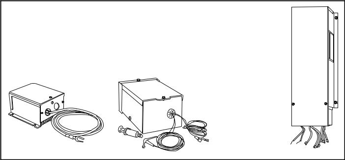
The 580D036 and 579F240 standard units are designed to operate in cooling at outdoor temperatures down to 25 F, the standard 579F180 unit operates down to 40 F, the standard 579F216 unit operates down to 35 F; and the standard 579F300 unit operates down to 48 F. With accessory Motormaster control (579F180,216) (condenser-fan speed modulation), Motormaster II control (condenser-fan cycling for units sizes 036-150), −20 F low-ambient kit (condenser fan sequencing for 579F180), or Motormaster III control (579F240,300) (condenser fan speed modulation) units can operate at outdoor temperatures down to −20 F. The head pressure controls, which mount in the condenser section, control the condenser-fan motor to maintain correct condensing temperature. Refer to Trade Prices or contact your local representative for appropriate accessory combinations for desired outdoor ambient temperature operation.
MOTORMASTER II CONTROL (036-150)
MOTORMASTER CONTROL |
MOTORMASTER III |
CONTROL |
|
(180,216) |
(240,300) |
14
OPTIONS AND ACCESSORIES (cont)
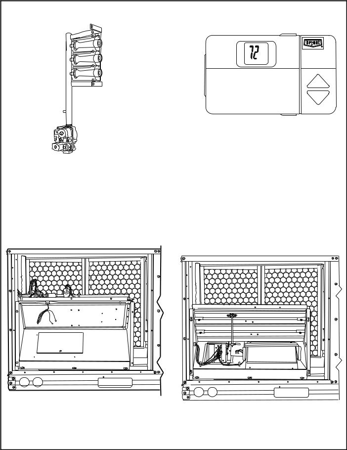
LIQUID PROPANE (LP) CONVERSION KITS |
BRYANT COMMERCIAL |
|
PROGRAMMABLE THERMOSTAT |
036-072 SHOWN
The LP conversion kit allows the unit to utilize a liquid propane fuel supply in areas where natural gas is unavailable, and permits the unit to be converted from natural gas to LP gas use. The kit contains the ori®ces required for LP operation.
Designed speci®cally for use with Bryant commercial systems, this Bryant programmable thermostat features LED occupied/unoccupied displays and setback mode which can override continuous fan operation.
TIME GUARDT II CONTROL
Time Guard II control automatically prevents compressor from restarting for at least 5 minutes after a shutdown. Accessory prevents short cycling of compressor if thermostat is changed rapidly. Time Guard II control mounts in the control compartment of unit.
DURABLADE ECONOMIZER
(SIZES 036-150) PARABLADE ECONOMIZER (SIZES 036-150)
Exclusive Durablade economizer damper design saves energy while providing economical and reliable cooling. A sliding plate on the face of the economizer controls the amount of outdoor air entering the system. Closed, it provides a leakproof seal which prevents ambient air from seeping in or conditioned air from seeping out. It can be adjusted easily for 100% outdoor air or any proportions of mixed air. Like the base unit, the economizer is converted easily for horizontal discharge applications.
The unique design of the Parablade economizer saves energy while providing economical and reliable cooling. The design uses a parallelopposed blade damper. The economizer also has built-in spring return for reliable close-on-power-loss. The Parablade design incorporates standard enthalpy controls and up to 45% barometric relief capability for additional ¯exibility in high outdoor air¯ow applications.
15
ACCUSENSOR™ II
CONTROL
(036-150 Only)
|
|
|
|
|
|
|
|
|
|
|
|
|
|
|
|
B |
REV |
|
|
|
|
|
|
|
|
|
|
|
|
|
|
|
|
|
. |
|
OPEN |
|
|
|
POSITIONMINIMUM |
|
|
|
|
|
|
|
|
|
|
|
B |
|
|
|
|
|
|
|
|
|
|
|
|
|
|
|
A |
||
|
|
|
|
|
|
|
|
|
|
|
|
|
|
|
|
C |
1 |
|
|
|
|
|
|
|
|
|
|
|
|
|
|
|
S |
TR |
1 |
|
|
|
|
|
|
|
|
|
|
|
|
|
|
D |
|
|
8 |
|
|
|
|
|
|
|
|
|
|
|
|
S |
O |
|
8 |
||
|
|
|
T |
|
3 |
|
1 |
|
|
|
|
|
|
|
|
|
|
|
P |
|
|
|
|
|
|
|
|
|
|
|
|
|
|
||
|
|
|
|
|
|
|
|
|
|
|
|
|
|
|
|
|
|
|
|
|
T1 |
|
4 |
|
2 |
|
|
5 |
|
|
|
|
|
|
|
|
P1 |
|
|
|
|
|
|
|
|
|
|
|
|
||||
|
|
|
|
|
|
|
|
|
|
|
|
|
|
|
|
|
|
|
YT ID |
|
|
D |
|
RUSH |
CONTACT |
OR |
CONT |
3 |
TR |
|
|
|
|
|
|
|
10 30 60 |
|
|
AT |
ACTS |
|
|
|
|
|
|||||||
|
50 |
|
IMUH% |
– |
24VAC |
|
UNPOWERED |
SHO |
|
|
|
|
|
|
|
||
|
|
|
|
C |
|
|
|
|
|
|
|
|
|||||
OUTDOOR |
60 |
|
|
70 |
90 |
CW |
mA |
5A |
STATE |
HIGH |
2 |
|
ENTHALPY |
|
|
|
|
|
|
DAMPER |
|
|
|
RATINGS: |
|
|
|
|
|
|
|
|
|
||
|
55 |
|
B |
SETPOINTS |
|
|
WN |
|
24VAC |
|
|
|
|
|
|||
|
|
|
|
3 . |
|
|
|
|
|
|
|
|
|
||||
|
|
OPEN |
|
|
A |
|
1 |
|
IN |
|
|
CONTROL |
|
|
|
|
|
|
|
|
CLOSED |
|
VDC |
|
|
|
|
|
|
|
|||||
F |
75 |
|
|
DAMPER |
|
RUN, |
|
|
1 |
TR1 |
|
|
|
|
|||
|
70 65 |
|
|
|
|
|
. |
|
|
|
|
|
|
|
|
|
|
|
|
|
|
|
CCW |
MIN |
IN |
|
ENTHALPY |
|
|
|
|
|
|
|
|
° |
|
|
|
|
11 |
|
|
|
|
|
|
|
|
||||
TEMP |
|
|
|
|
– |
AT |
3 |
|
|
|
|
|
|
|
|
|
|
. |
|
|
|
|
|
|
. |
|
|
|
|
|
|
|
|
|
|
|
|
|
|
|
|
|
|
5A |
|
|
|
|
|
|
|
|
|
|
80 |
|
|
|
|
|
|
|
|
|
|
|
|
|
|
|
|
|
85 |
REV. |
|
97-3672 |
|
|
|
|
|
|
|
|
|
|
|
|
|
OPTIONS AND ACCESSORIES (cont)
POWER EXHAUST (180-300 SHOWN)
ACCUSENSOR III
SENSOR
+
When used with accessory/optional economizer, the power exhaust accessory helps to relieve building over-pressurization.
NOTE: This accessory is not available with horizontal supply adapter.
Accusensor economizer controls help provide efficient, economical economizer operation. Accusensor II solid-state enthalpy control includes the logic and one sensor to calculate both dryand wet-bulb of the outdoor air to provide an accurate enthalpy reading on 036-150 units. It then decides when to energize the economizer based on this reading. The 180-300 unit economizer provides the decision-making function internally, and requires one Accusensor III sensor for solid-state enthalpy sensing. A second Accusensor III sensor (required for all units for differential enthalpy sensing) compares outdoor temperature and humidity to return-air temperature and humidity and determines the most economical mixture of air (purchased in addition to enthalpy control [sizes 036-150] or to ®rst solid-state enthalpy sensor [sizes 180-300] for differential enthalpy sensing).
THERMOSTAT
H |
C |
Thermostat (24 v) provides oneor 2-stage cooling for control of unit. Matching subbases are available with or without tamperproof switches and automatic changeover.
16
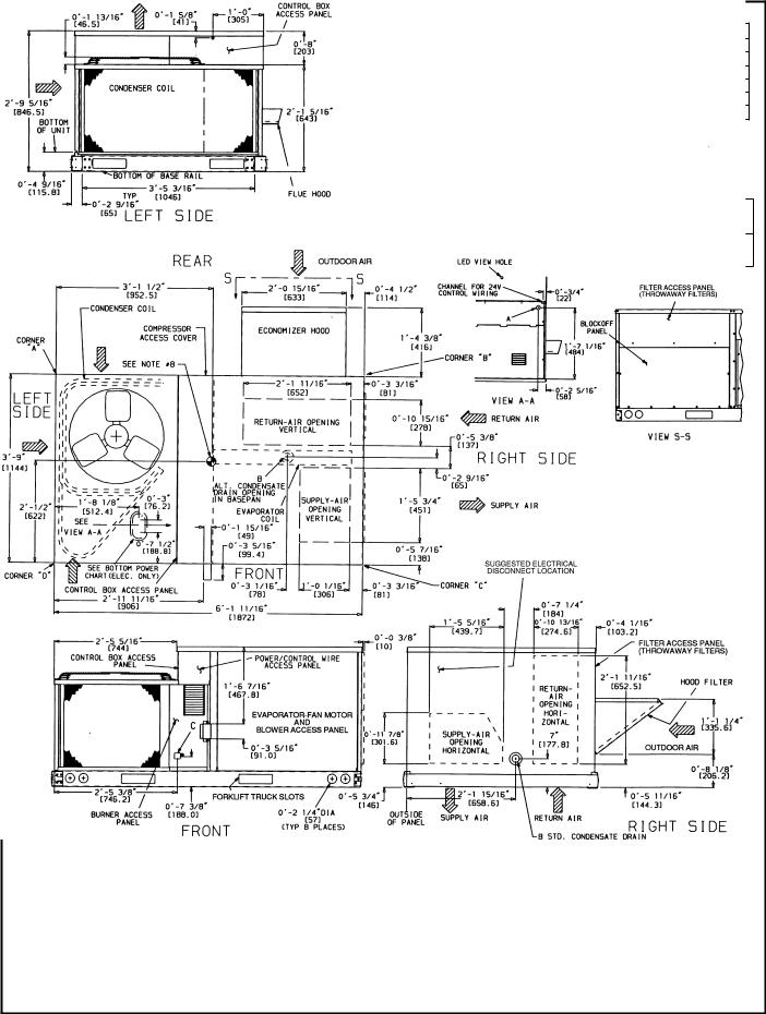
BASE UNIT DIMENSIONS Ð 580D036-072
NOTES:
1. Dimensions in [ ] are in millimeters.
2. Center of gravity.
3. Direction of air¯ow.
4.On vertical discharge units, ductwork to be attached to accessory roof curb only. For horizontal discharge units, ®eld-supplied ¯anges should be attached to horizontal discharge openings, and all ductwork should be attached to the ¯anges.
5.Minimum clearance (local codes or jurisdiction may prevail):
a.Between unit, ¯ue side and combustible surfaces, 36 inches.
b.Bottom of unit to combustible surfaces (when not using curb), 1 inch. Bottom of base rail to combustible surfaces (when not using curb) 0 inches.
c.Condenser coil, for proper air¯ow, 36 in. one side, 12 in. the other. The side getting the greater clearance is optional.
d.Overhead, 60 in. to assure proper condenser fan operation.
e.Between units, control box side, 42 in. per NEC (National Electrical Code).
f.Between unit and ungrounded surfaces, control box side, 36 in. per NEC.
g.Between unit and block or concrete walls and other grounded surfaces, control box side, 42 in. per NEC.
h.Horizontal supply and return end, 0 inches.
6.With the exception of the clearance for the condenser coil and combustion side as stated in Notes 5a, b, and c, a removable fence or barricade requires no clearance.
7.Units may be installed on combustible ¯oors made from wood or Class A, B, or C roof covering material if set on baserail.
8.The vertical center of gravity is 18-69 [457] up from the bottom of the base rail. Horizontal center of gravity is shown.
17
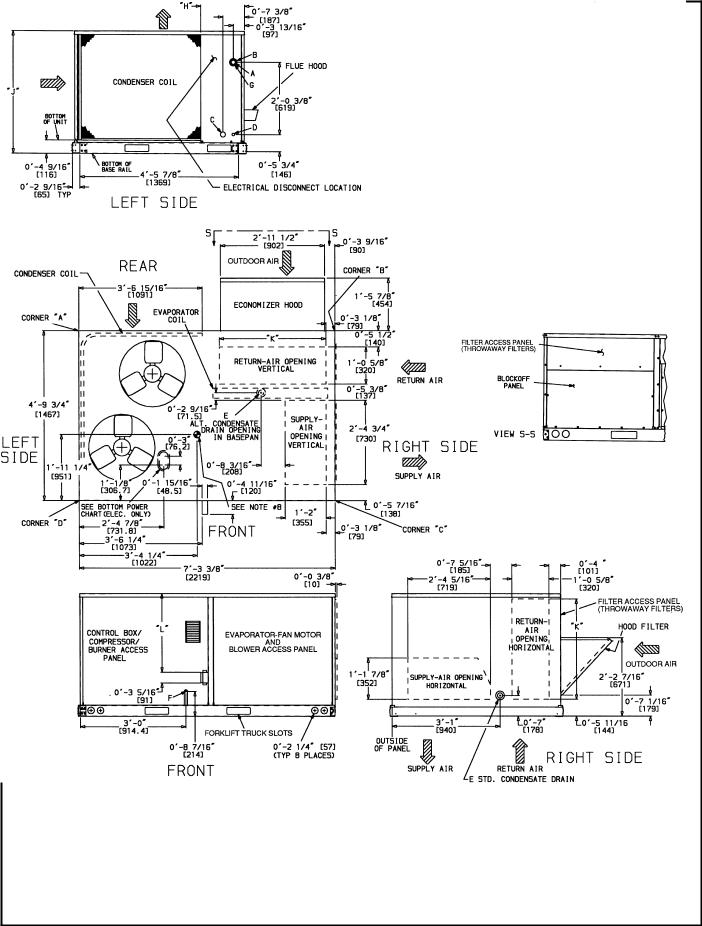
BASE UNIT DIMENSIONS Ð 580D090-150
UNIT |
|
|
|
CORNER WEIGHT* |
|
|
|
|
|
|
|
|
|
|
DIMENSIONS |
|
|
|
|
|
CONNECTION SIZES |
|||||||||||
|
A |
B |
|
|
C |
|
D |
|
|
``H'' |
|
|
``J'' |
|
|
|
``K'' |
|
``L'' |
|
|
A |
13¤89 |
Dia [35] Field Power Supply Hole |
||||||||
580D |
|
|
|
|
|
|
|
|
|
|
|
|
|
|
|
|
|
|
|
|
|
|
|
|
|
|
|
|
|
B |
21¤29 |
Dia [64] Power Supply Knockout |
|
lb |
|
kg |
lb |
|
kg |
lb |
|
kg |
lb |
|
kg |
ft-in. |
mm |
ft-in. |
mm |
|
ft-in. |
|
mm |
ft-in. |
mm |
|
C |
13¤49 |
Dia [44] Charging Port Hole |
||||||
090 |
189 |
|
86 |
161 |
|
73 |
239 |
|
109 |
280 |
|
127 |
1-27¤8 |
378 |
3-55¤16 |
1050 |
|
2-911¤16 |
|
856 |
2- 27¤16 |
672 |
|
D |
7¤89 Dia [22] Field Control Wiring Hole |
|||||||
|
|
|
|
|
|
|
|
|
|
|
|
|
|
|
|
|
|
|
|
|
|
|
|
|
|
|
|
|
|
E |
3¤49Ð14 NPT Condensate Drain |
|
102 |
191 |
|
87 |
163 |
|
74 |
242 |
|
110 |
284 |
|
129 |
3-37¤8 |
1013 |
3-55¤16 |
1050 |
|
2-911¤16 |
|
856 |
2- 27¤16 |
672 |
||||||||||
|
|
|
|
|
|
|
F |
1¤29Ð14 NPT Gas Connection 090 125 & 102 125 |
||||||||||||||||||||||||
120 |
225 |
|
102 |
192 |
|
87 |
285 |
|
129 |
333 |
|
151 |
2-5 |
7 |
¤8 |
759 |
4-1 |
5 |
¤16 |
1253 |
|
3-0 |
3 |
¤8 |
|
924 |
7 |
875 |
|
|
3¤49Ð14 NPT Gas Connection All Others |
|
|
|
|
|
|
|
|
|
|
2-10 ¤16 |
|
G |
29 Dia [51] Power Supply Knockout |
||||||||||||||||||||
150 |
228 |
|
103 |
195 |
|
88 |
289 |
|
131 |
338 |
|
153 |
1-27¤8 |
378 |
4-15¤16 |
1253 |
3-03¤8 |
|
924 |
2-107¤16 |
875 |
|
||||||||||
|
|
|
|
|
|
|
|
|
||||||||||||||||||||||||
|
|
|
|
|
|
|
|
|
||||||||||||||||||||||||
*Weights are for units only (aluminum plate ®ns) and do not include options or crating. |
|
|
|
|
NOTES: |
|
] are in millimeters. |
|||||||||||||||||||||||||
|
|
|
|
|
|
|
|
|
|
|
|
|
|
|
|
|
|
|
|
|
|
|
|
|
|
1. |
Dimensions in [ |
|||||
-
BOTTOM POWER CHART, THESE HOLES
REQUIRED FOR USE WITH ACCESSORY
PACKAGES Ð CRBTMPWR001A00 ( 1¤29, 3¤49)
OR CRBTMPWR002A00 (1¤29, 11¤49)
THREADED |
WIRE SIZE |
REQUIRED HOLE |
||
CONDUIT SIZE |
SIZES (MAX) |
|||
|
||||
|
|
|
|
|
1¤2( |
24 V |
7¤89 |
[22.2] |
|
3¤4( |
Power² |
1 1¤89 |
[28.4] |
|
11¤4( |
Power² |
1 3¤49 |
[44.4] |
|
²Select either 3¤49 or 11¤49 for power, depending on wire size.
18
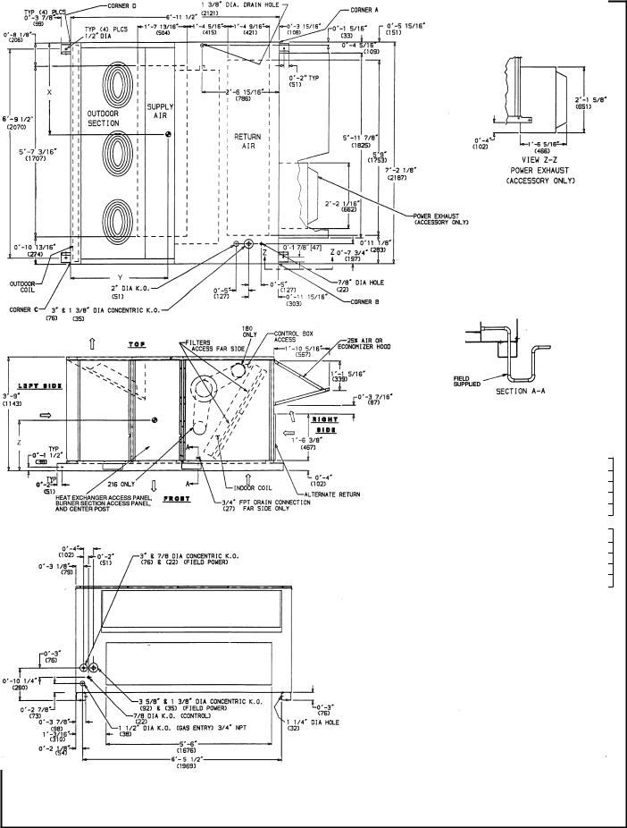
BASE UNIT DIMENSIONS Ð 579F180,216
-
7.Dimensions are from outside of corner post. Allow 08-5¤169 (8) on each side for top panel drip edge.
8.Do not locate adjacent units with ¯ue discharge facing economizer inlet.
19

BASE UNIT DIMENSIONS Ð 579F240,300
300 527 239 545 247 578 262 600 272 3-7 1092
*Weights are for unit only (aluminum plate ®ns) and do not include options or crating.
20
ACCESSORY DIMENSIONS
ROOF CURB |
``A'' |
UNIT SIZE |
||
ACCESSORY |
580D |
|||
|
|
|||
CRRFCURB001A00 |
18-29 |
[356] |
036-072 |
|
CRRFCURB002A00 |
28-09 |
[610] |
||
|
||||
|
|
|
|
|
UNIT SIZE |
|
|
``D'' ALT |
``E'' |
|
|
|
CONNECTOR |
|
``B'' |
``C'' |
DRAIN |
POWER |
CONTROL |
|||||
580D |
GAS |
PKG ACY |
|||||||
|
|
HOLE |
|
|
|
||||
|
|
|
|
|
|
|
|
||
|
|
|
|
3¤49 NPT |
3¤49 NPT |
1¤29 |
NPT |
CRBTMPWR001A00* |
|
|
18-911¤169 |
18-49 |
|
(Thru-The-Bottom) |
|||||
036-072 |
13¤49 [45] |
|
|
|
|
||||
[551] |
[406] |
3¤49 NPT |
11¤49 NPT |
1¤29 |
NPT |
CRBTMPWR002A00* |
|||
|
|
||||||||
|
|
|
|
(Thru-The-Bottom) |
|||||
|
|
|
|
|
|
|
|
||
|
|
|
|
|
|
|
|
|
|
*Either connector package available for either roof curb.
Roof Curb Ð 580D036-072
21
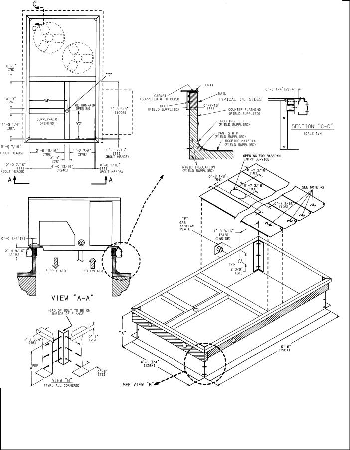
ACCESSORY DIMENSIONS (cont)
ROOF CURB |
|
UNIT |
|
``A'' |
SIZE |
||
ACCESSORY |
|||
|
580D |
||
|
|
||
CRRFCURB003A00 |
18-29 |
|
|
[356] |
090- |
||
|
|||
CRRFCURB004A00 |
28-09 |
150 |
|
[610] |
|
||
|
|
UNIT |
|
|
``D'' ALT |
``E'' |
|
|
CONNECTOR |
|
SIZE |
``B'' |
``C'' |
DRAIN |
POWER |
CONTROL |
PACKAGE |
||
GAS |
||||||||
580D |
|
|
HOLE |
|
|
ACCESSORY |
||
|
|
|
|
|
||||
|
|
|
|
|
|
|
CRBTMPWR001A00* |
|
|
|
|
|
3¤49 NPT |
3¤49NPT |
1¤29 NPT |
(THRU-THE-BOTTOM |
|
090- |
28-87¤169 |
18-1015¤169 |
13¤49 |
|
|
|
CONNECTIONS) |
|
150 |
[827] |
[583] |
[45] |
|
|
|
CRBTMPWR002A00* |
|
|
|
|
|
3¤49 NPT |
11¤49 NPT |
1¤29 NPT |
(THRU-THE-BOTTOM |
|
|
|
|
|
|
|
|
|
Roof Curb Ð 580D090-150
22
 Loading...