


 Loading...
COMMERCIAL |
580F, 579F, 581A/B |
|
DuraPac and |
||
SINGLE PACKAGE ROOFTOP UNITS |
||
DuraPac Plus Series |
||
GAS HEATING/ELECTRIC COOLING UNITS |
||
|
Sizes 036-300 |
|
|
3 to 25 Tons |
|
|
|
|
50-1242f |
|
579F180-216 |
48-910df |
SIZES 036-073 |
50-1214df |
|
SIZES 090-151 |
|
581A155,180 |
|
|
|
||
|
|
|
580F180,210 |
581A210-300 |
a48-8207 |
580F240 |
a48-5997 |
580F300 |
|
|
579F240-300 |
48-831df |
|
Standard efficiency units (580F072, 090, 120, 150 and 579F180-300) are available. Standard efficiency units (580F036-060, 073, 091,103,121,151, and 180-300) that meet ASHRAE 90.1-04 minimum energy efficiency requirements are also available. High efficiency units (581B036-150 and 581A155-300) well exceed ASHRAE 90.1-04 energy efficiency requirements and must comply with Energy Star high efficiency requirements. Gas heating with electric cooling rooftops offer:
•Pre-painted galvanized steel cabinet for long life and quality appearance
•Commercial strength base rails with built-in rigging capability
•Convertible design for vertical or horizontal supply/return (036-151 and 210-300 only)
•Non-corrosive, sloped condensate drain pan, meets ASHRAE 62 (IAQ)
•Two-inch return-air filters
•A wide assortment of factory-installed options available, including high-static drives that provide additional performance range
•Factory-installed optional gear driven EconoMi$er IV (vertical return for sizes 036-151 only) for use with standard rooftop unit controls (includes CO2 sensor control capability)
•Factory-installed optional gear driven EconoMi$er2 (vertical return only) for use with third party DDC controls (includes 4 to 20 mA actuator for demand control ventilation)
•Perfect Humidity™ dehumidification package (581B036-150 only)
•Hot gas reheat dehumidification package (581A181-300 only)
Heat Options
•Exclusive integrated gas control board with diagnostics
•Alumagard™ heat exchanger coating
•Induced-draft fan for gas combustion
•Tubular, dimpled heat exchangers
•Natural gas
•LP conversion kits
•Low NOX (size 036-060 only)
•Optional stainless steel heat exchangers.
FEATURES/BENEFITS
Every compact one-piece unit arrives fully assembled, charged, tested, and ready to run.
GAS HEAT MODELS — All ignition components are contained in the compact IGC (integrated gas controller) which is easily accessible for servicing. The IGC control board, designed and manufactured exclusively for Bryant rooftop units, provides built-in diagnostic capability. An LED (light-emitting diode) simplifies troubleshooting by providing visual fault notification and system status confirmation.
The IGC also contains an exclusive anti-cycle protection for gas heat operation. After 4 continuous cycles on the unit hightemperature limit switch, the gas heat operation is disabled, and an error code is issued. This feature greatly improves reliability of the rooftop unit.
The IGC also contains burner control logic for accurate and dependable gas ignition. The LED is visible without removing the unit control box access panel. This LED fault-notification system reduces service person troubleshooting time and minimizes service costs. The IGC also maximizes heating efficiency by controlling evaporator-fan on and off delays.
Tubular, dimpled gas heat exchangers optimize heat transfer for improved efficiency. The tubular design permits hot gases to make multiple passes across the path of the supply air. The dimpled design creates a turbulent gas flow to maximize heating efficiency.
Form No. PDS 580F.36.3
TABLE OF CONTENTS
Page
Features/Benefits . . . . . . . . . . . . . . . . . . . . . . . . . . . . . . . . . 1-4
Model Number Nomenclature . . . . . . . . . . . . . . . . . . . . . . . . 5-7
ARI Capacity Ratings . . . . . . . . . . . . . . . . . . . . . . . . . . . . . 8-15
Options and Accessories . . . . . . . . . . . . . . . . . . . . . . . . . 16-19
580F036-151
Physical Data . . . . . . . . . . . . . . . . . . . . . . . . . . . . . . . . . . 20-25 Base Unit Dimensions. . . . . . . . . . . . . . . . . . . . . . . . . . . . 26-29 Accessory Dimensions . . . . . . . . . . . . . . . . . . . . . . . . . . . 30,31 Selection Procedure . . . . . . . . . . . . . . . . . . . . . . . . . . . . . . . .32 Performance Data . . . . . . . . . . . . . . . . . . . . . . . . . . . . . . . 33-74 Electrical Data. . . . . . . . . . . . . . . . . . . . . . . . . . . . . . . . . . 75-78 Typical Wiring Schematics . . . . . . . . . . . . . . . . . . . . . . . . 79-81 Typical Piping and Wiring . . . . . . . . . . . . . . . . . . . . . . . . . . . .82
581B036-150
Physical Data . . . . . . . . . . . . . . . . . . . . . . . . . . . . . . . . . . 83-86 Base Unit Dimensions. . . . . . . . . . . . . . . . . . . . . . . . . . . . 87,88 Accessory Dimensions . . . . . . . . . . . . . . . . . . . . . . . . . . . 89,90 Selection Procedure . . . . . . . . . . . . . . . . . . . . . . . . . . . . . . . .91 Performance Data . . . . . . . . . . . . . . . . . . . . . . . . . . . . . . 92-132 Electrical Data. . . . . . . . . . . . . . . . . . . . . . . . . . . . . . . . 133,134 Typical Wiring Schematics . . . . . . . . . . . . . . . . . . . . . . 135-137 Typical Piping and Wiring . . . . . . . . . . . . . . . . . . . . . . . . . . .138
Guide Specifications (036-151 Size Units) . . . . . . . . 139-143
579F180-300
Physical Data . . . . . . . . . . . . . . . . . . . . . . . . . . . . . . . . 144,145 Base Unit Dimensions. . . . . . . . . . . . . . . . . . . . . . . . . . 146,147 Accessory Dimensions . . . . . . . . . . . . . . . . . . . . . . . . . 148-150 Selection Procedure . . . . . . . . . . . . . . . . . . . . . . . . . . . . . . .151 Performance Data . . . . . . . . . . . . . . . . . . . . . . . . . . . . . 152-165 Electrical Data. . . . . . . . . . . . . . . . . . . . . . . . . . . . . . . . . . . .166 Typical Wiring Schematics . . . . . . . . . . . . . . . . . . . . . . 167-170 Typical Piping and Wiring . . . . . . . . . . . . . . . . . . . . . . . . . . .171
580F180-300
Physical Data . . . . . . . . . . . . . . . . . . . . . . . . . . . . . . . . 172,173 Base Unit Dimensions. . . . . . . . . . . . . . . . . . . . . . . . . . 174-176 Accessory Dimensions . . . . . . . . . . . . . . . . . . . . . . . . . 177-180 Selection Procedure . . . . . . . . . . . . . . . . . . . . . . . . . . . . . . .181 Performance Data . . . . . . . . . . . . . . . . . . . . . . . . . . . . . 182-191 Electrical Data. . . . . . . . . . . . . . . . . . . . . . . . . . . . . . . . . . . .192 Typical Wiring Schematics . . . . . . . . . . . . . . . . . . . . . . 193-195 Typical Piping and Wiring . . . . . . . . . . . . . . . . . . . . . . . . . . .196
581A155-300
Physical Data . . . . . . . . . . . . . . . . . . . . . . . . . . . . . . . . 197-200 Base Unit Dimensions. . . . . . . . . . . . . . . . . . . . . . . . . . 201,202 Accessory Dimensions . . . . . . . . . . . . . . . . . . . . . . . . . 203-206 Selection Procedure . . . . . . . . . . . . . . . . . . . . . . . . . . . . . . .207 Performance Data . . . . . . . . . . . . . . . . . . . . . . . . . . . . . 208-243 Electrical Data. . . . . . . . . . . . . . . . . . . . . . . . . . . . . . . . 244-246 Typical Wiring Schematics . . . . . . . . . . . . . . . . . . . . . . 247,248 Typical Piping and Wiring . . . . . . . . . . . . . . . . . . . . . . . . . . .249
Guide Specifications (155-300 Size Units) . . . . . . . . 250-258
Controls. . . . . . . . . . . . . . . . . . . . . . . . . . . . . . . . . . . . . 259-262
Application Data . . . . . . . . . . . . . . . . . . . . . . . . . . . . . . 263-266
Index . . . . . . . . . . . . . . . . . . . . . . . . . . . . . . . . . . . . . . . . . . .267
FEATURES/BENEFITS (cont)
The efficient in-shot burners and all ignition components are contained in an easily removable, compact assembly.
The California Air Quality Management Districts NOx requirement of 40 nanograms/joule or less is met on 036-060 size Low NOx models.
The extra thick Alumagard™ heat exchanger coating provides corrosion resistance and ensures long life (optional stainless steel heat exchangers are available).
The unsightly appearance of flue stacks is eliminated and the effects of wind on heating operations are diminished by the induced draft combustion system. The inducer fan draws hot combustion gas through the heat exchanger at the optimum rate for the most effective heat transfer. The heat exchanger operates under negative pressure, preventing flue gas leakage into the indoor supply air.
During the heating mode, the evaporator-fan relay automatically starts the evaporator fan after the heat exchanger warms up to a suitable temperature. The 30-second fan delay prevents cold air from entering the supply duct system when the conditioned space is calling for heat to maximize efficiency.
The direct-spark ignition system saves operating expense when compared to pilot ignition systems. No crossover tube is required, therefore no sooting or pilot fouling problems can occur.
All standard units are designed for natural gas, but an accessory LP (liquid propane) conversion kit is available.
All units have a flame rectification sensor to quickly sense the burner flame and ignite burners almost immediately. Fast shutdown is a certainty since the sensor reacts quickly to any flame outage or system failure. In the event of a shutdown, an error code is issued at the IGC board.
Safety is also assured due to the heating safety controls which will shut down the unit if there is a problem. If excessive temperatures develop, limit switches shut off the gas valve. After 4 continuous short cycles of the high-temperature limit switch, the IGC board locks out the gas heat cycle to prevent any further short cycles. This safety feature is provided exclusively on Bryant rooftop units. The rollout switch also deenergizes the gas valve in the event of a flame rollout.
QUIET, EFFICIENT OPERATION AND DEPENDABLE PERFORMANCE — Compressors have vibration isolators for quiet operation. Efficient fan and motor design permits operation at low sound levels.
Unit sizes 090-300 offer lower utility costs through part-load operation using 2 or 3 stages of cooling.
Quiet and efficient operation is provided by belt-driven evaporator fans (standard on all units over 5 tons). The belt-driven evaporator-fan is equipped with variable-pitch pulleys which allow adjustment within the rpm ranges of the factory-supplied pulleys.
Increased operating efficiency is achieved through computerdesigned coils featuring staggered internally enhanced copper tubes. Fins are ripple-edged for strength, lanced, and double waved for higher heat transfer.
DURABLE, DEPENDABLE CONSTRUCTION — Designed for durability in any climate, the weather-resistant cabinets are constructed of galvanized steel and bonderized, and all exterior panels are coated with a prepainted baked enamel finish. The paint finish is non-chalking, and is capable of withstanding ASTM (American Society for Testing and Materials) B117 500-hour Salt Spray Test. All internal cabinet panels are primed, permitting longer life and a more attractive appearance for the entire unit.
In addition, all size 036-151 units are designed with a single, continuous top piece to eliminate any possible leaks at seams or gasketing. Totally enclosed condenser-fan motors and permanently lubricated bearings provide additional unit dependability.
EASY INSTALLATION AND CONVERSION
All Units are Shipped in the Vertical Duct Configuration for fit-up to standard roof curbs. The contractor can order and install the roof curb early in the construction stage, before decisions on size requirements are made.
All units feature a base rail design with forklift slots and rigging holes for easier maneuvering. Durable packaging protects all units during shipment and storage.
2
FEATURES/BENEFITS (cont)
The units can be easily converted from a vertical to a horizontal duct configuration by relocating the panels supplied with the unit (size 036-150 only).
To Convert 036-151 Units from vertical to horizontal discharge, simply relocate 2 panels. The same basic unit can be used for a variety of applications and can be quickly modified at the jobsite.
To Convert 155-300 Units from vertical to horizontal discharge, use the optional horizontal supply/return adapter roof curb (581A155,180 and 579F/580F180-300) or accessory conversion kit (581A210-300). Please note that 581A210-300 units are available from the factory configured for horizontal supply/return.
Convenient Duct Openings in the unit basepans permit side- by-side or concentric duct connections (see Application data section) without requiring internal unit modification.
NOTE: On units using horizontal supply and return, the accessory barometric relief or power exhaust MUST be installed on the return ductwork.
Thru-The-Bottom Service Connection Capability comes standard with the rooftop unit to allow power and control wiring and gas connections to be routed through the unit’s basepan, thereby minimizing roof penetrations (to prevent water leaks). (Thru-the-bottom gas connection requires thru-the-bottom accessory kit.) Power, gas and control connections are made on the same side of the unit to simplify installation.
The Non-Corrosive Sloped Condensate Drain Pan (Size 036-150) permits either an external horizontal side condensate drain (outside the roof curb) or an internal vertical bottom drain (inside the roof curb). Both options require an external, field-supplied P-trap.
Standard 2-in. Throwaway Filters are easily accessed through a removable panel located above the air intake hood. No tools are required to change unit filters.
Belt-Driven Evaporator-Fan Motors (optional on 580F units under 6 tons) allow maximum on-site flexibility without changing motors or drives.
Low Voltage Wiring Connections are easily made thanks to the large terminal board which is located for quick, convenient access.
In addition, color-coded wires permit easy tracing and diagnostics.
PROVEN COMPRESSOR RELIABILITY — Design techniques feature computer-programmed balance between compressor, condenser, and evaporator. Bryant-specified hermetic compressors are equipped with compressor overcurrent and overtemperature protection to ensure dependability.
All units have Bryant’s exclusive Acutrol™ (036-150) or TXV (thermostatic expansion valve) metering device (155-300) which precisely controls refrigerant flow, preventing slugging and flood-back, while maintaining optimum unit performance. Refrigerant filter driers are standard.
INTEGRATED ECONOMIZERS AND OUTDOOR-AIR DAMPERS — Available as options or accessories, economizers and manual outdoor-air dampers introduce outdoor air which mixes with the conditioned air, improving indoor-air quality and often reducing energy consumption.
During a first stage call for cooling, if the outdoor-air temperature is below the economizer control changeover set point, the mixed-air sensor modulates the economizer outdoor-air damper open to take advantage of free cooling provided by the outside air. When second-stage cooling is called for, the compressor is energized in addition to the economizer. If the outdoor-air temperature is above the changeover set point, the first stage of compression is activated and the economizer damper stays at minimum position.
Accessory upgrade kits allow for control by differential dry-bulb temperature (outdoor vs return), outdoor air enthalpy changeover, or more precise differential enthalpy control.
Units can be equipped with different economizer options to meet specific controls applications. The factory-installed or field-installed EconoMi$er IV and EconoMi$er2 are available. The EconoMi$er IV is used with the standard rooftop unit controls and includes an industry standard, stand-alone, solid-state controller. The control can be used with a CO2 sensor for DCV (demand control ventilation) operation. For direct digital control (DDC) applications, the EconoMi$er2 can be operated using a third party control system. The EconoMi$er2 includes 4 to 20 mA actuator capability for demand control ventilation applications.
All economizers incorporate a parallel blade, gear-driven damper system for efficient air mixing and reliable control. In addition, the standard damper actuator includes a spring return to provide reliable closure on power loss. The economizers for sizes 036-151 are equipped with up to 100% barometric relief capability for high outdoor airflow operations. Economizers for unit sizes 036-151 are available, factory-installed, for vertical return only. Economizers for unit sizes 155-300 are compatible for vertical or horizontal return. An optional field-installed barometric relief package is available for size 155-300 units.
In addition, single-stage power exhaust is available as a fieldinstalled accessory for EconoMi$er IV to help maintain proper building pressure.
For units without economizer, year-round ventilation is enhanced by an optional manual outdoor-air damper. On 036150 units, a 25% or 50% manual damper is available as a fieldinstalled accessory. Unit sizes 155-300 are equipped with a manual 25% damper.
SERVICE OPTIONS (581B and 581A Units Only) — Servicing a rooftop unit has never been easier with the factory-installed service options for these rooftop units. These options include the following:
•Hinged access panels are provided for the filter/indoor-fan motor, compressors, evaporator fan, and control box areas. Quick access to major components is accomplished by simply unlatching and swinging open the various panels. Each hinged panel is permanently mounted to the unit, thereby eliminating the concern of a dropped or wind-blown panel puncturing delicate roof materials. The 4 extended access panels are also equipped with ‘‘tie back’’ retaining devices to hold the door in the open position while servicing the unit.
•An external, covered, 115-v Ground Fault Interrupt (GFI) receptacle is provided as a convenient power source for drills, lights, refrigerant recovery units, or other electrical service tools. A factory-supplied step down transformer is connected to the “load” side of the unit main power connection (size 036150). For sizes 155-300, connect the outlet to a field-supplied and properly fused branch circuit power supply.
•Slide out “motor-drive-blower” reduces service time (only on 581A210-300).
•An integral non-fused disconnect switch within the rooftop unit reduces installation time, labor and material costs. Safety is assured by an interlock which prevents access to the control box unless the switch is in the OFF position. In addition, the externally mounted handle incorporates power lockout capability to further protect service personnel.
3
FEATURES/BENEFITS (cont)
INDOOR-AIR QUALITY (IAQ) BEGINS WITH BRYANT ROOFTOPS — Sloped condensate pans minimize biological growth in rooftop units in accordance with ASHRAE (American Society of Heating, Refrigeration and Air Conditioning Engineers) Standard 62. Two-inch filters with optional dirty filter indicator switch provide for greater particle reduction in the return air. The face-split evaporator coils improve the dehumidification capability of standard units, maximize building humidity control.
Optional proportional reacting CO2 sensor is available with the EconoMi$er IV outdoor air damper option/accessory to aid the IAQ benefits.
PERFECT HUMIDITY™ ADAPTIVE DEHUMIDIFICATION SYSTEM (581B036-150 only) — Bryant’s Perfect Humidity adaptive dehumidification system is an all-inclusive factoryinstalled option that can be ordered with any 581B rooftop unit to meet the demand for providing a flexible and high performing solution to accommodate all of these design related issues. This system expands the envelope of operation of 581B rooftop products to provide unprecedented flexibility to meet year-round comfort conditions. The Perfect Humidity adaptive dehumidification system has the industry’s only dual dehumidification mode setting. The Perfect Humidity system includes two new modes of operation. The 581B rooftop coupled with the Perfect Humidity system is capable of operating in normal design cooling mode, subcooling mode, and hot gas reheat mode. Normal Design Cooling mode is when the unit will operate under its normal sequence of operation by cycling compressors to maintain comfort conditions. Subcooling mode will operate to satisfy part load type conditions when the space requires combined sensible and a higher proportion of latent load control. Hot Gas
Reheat mode will operate when outdoor temperatures diminish and the need for latent capacity is required for sole humidity control. Hot Gas Reheat mode will provide neutral air for maximum dehumidification operation.
EXCLUSIVE HOT GAS REHEAT DEHUMIDIFICATION PACKAGE (581A181-300) — The hot gas reheat dehumidification package is a result of recent advances by Bryant in controlling comfort levels. This factory-installed option significantly improves the dehumidification capability of the rooftop unit and helps control humidity levels in the building.
This option provides increased dehumidification by cooling the hot liquid refrigerant leaving the condenser coil. The hot gas reheat package consists of a subcooling coil located on the leaving-air side of the evaporator coil. The location of this coil in the indoor airstream enhances the latent capacity of the units by as much as 40%. Many buildings suffer from humidity damage or poor indoor air quality due to humid conditions. The improved latent capacity provided by the hot gas reheat option reduces the building’s humidity, eliminating potential property damage and making the space more comfortable.
The hot gas reheat option is the ideal IAQ option for hot and humid regions. The operation of the hot gas reheat package can be controlled by a field-installed, wall mounted humidistat or Thermidistat™ device. The circuit activates only when needed (using the accessory humidistat) as opposed to some dehumidification systems that operate continuously. The humidistat can be set for any humidity level between 20% and 80% relative humidity. The Thermidistat device can be set for any humidity level between 50% and 90% relative humidity.
4

|
|
|
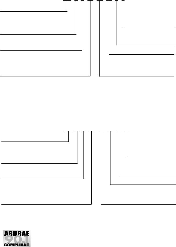
MODEL NUMBER NOMENCLATURE |
|
|
|
|
|
|
|||||||||||||||||||
|
|
580F036-150 (Standard and Medium Efficiency) 3 to 121/ Tons |
|
|
|
|
||||||||||||||||||||||
|
|
|
|
|
|
|
|
|
|
|
|
|
|
|
|
|
|
|
|
|
|
|
|
2 |
|
|
|
|
|
|
|
|
580F E V 060 |
120 N KB |
|
|
|
|
|
|
|||||||||||||||||
|
|
|
|
|
|
|
|
|
|
|
|
|
|
|
|
|
|
|
|
|
|
|
|
|
|
|||
580F – Packaged Rooftop |
|
|
|
|
|
|
|
|
|
|
|
|
|
|
|
|
|
Factory-Installed Options Code |
||||||||||
|
Standard Efficiency |
|
|
|
|
|
|
|
|
|
|
|
|
|
|
|
|
|||||||||||
|
|
|
|
|
|
|
|
|
|
|
|
|
|
|
|
|
|
|
|
|
|
|
|
|
||||
|
|
|
|
|
|
|
|
|
|
|
|
|
|
|
|
|
|
|
|
|
|
|
|
|
|
|
||
Voltage Designation |
|
|
|
|
|
|
|
|
|
|
|
|
|
|
|
|
|
|
|
|
|
|
|
|
|
|
||
J – 208/230-1-60 |
|
|
|
|
|
|
|
|
|
|
|
|
|
|
|
|
|
|
|
|
|
|
|
|
|
|
|
|
P – 208/230-3-60 |
|
|
|
|
|
|
|
|
|
|
|
|
|
|
|
|
|
|
|
|
Gas Heat Options |
|
|
|
|
|||
E – 460-3-60 |
|
|
|
|
|
|
|
|
|
|
|
|
|
|
|
|
|
|
|
|
A |
– Standard |
|
|
|
|
||
T – 575-3-60 |
|
|
|
|
|
|
|
|
|
|
|
|
|
|
|
|
|
|
|
|
N |
– Low NOx Unit |
|
|
|
|
||
Fuel Control Type/Heat Exchanger |
|
|
|
|
|
|
|
|
|
|
|
|
S |
– Stainless Steel Heat Exchanger |
||||||||||||||
|
|
|
|
|
|
|
|
|
|
|
|
|
|
|
|
|
|
|
||||||||||
|
|
|
|
|
|
|
|
|
|
|
|
|
|
|
|
|
|
|
||||||||||
V – Natural Gas/Direct Spark Ignition |
|
|
|
|
|
|
|
|
|
|
|
|
|
|
|
|
|
|
|
|||||||||
N – Low NOx Natural Gas/Direct Spark Ignition/Stainless |
|
|
|
|
|
|
|
|
|
|
|
|
|
|
|
|
|
|
|
|||||||||
|
Steel Heat Exchanger |
|
|
|
|
|
|
|
|
|
|
|
|
|
|
|
|
|
|
|
Gas Heat Input (Btuh) |
|
|
|
||||
|
|
|
|
|
|
|
|
|
|
|
|
|
|
|
|
|
|
|
|
|
|
|
|
|
||||
|
|
|
|
|
|
|
|
|
|
|
|
|
|
|
|
|
|
|
|
|
|
|
|
|||||
Nominal Tons |
|
|
|
|
|
|
|
|
|
|
|
|
|
|
|
|
|
|
|
|
Standard Units |
Low NOx Units |
||||||
036 |
– 3 |
091 |
– 7-1/2 (Medium Efficiency) |
|
|
|
074 |
– 74,000 |
060 |
– |
60,000 |
|
||||||||||||||||
048 |
– 4 |
103 |
– 8-1/2 (Medium Efficiency) |
|
|
|
115 |
– 115,000 |
090 |
– |
90,000 |
|
||||||||||||||||
060 |
– 5 |
120 |
– 10 |
|
|
|
125 |
– 125,000 |
120 |
– 120,000 |
||||||||||||||||||
072 |
– 6 |
121 |
– 10 (Medium Efficiency) |
|
|
|
150 |
– 150,000 |
|
|
|
|
||||||||||||||||
073 |
– 6 (Medium |
150 |
– 12-1/2 |
|
|
|
180 |
– 180,000 |
|
|
|
|
||||||||||||||||
|
Efficiency) |
151 |
– 12-1/2 (Medium Efficiency) |
|
|
|
224 |
– 224,000 |
|
|
a48-8190 |
|||||||||||||||||
090 |
– 7-1/2 |
|
|
|
|
|
|
|
|
|
|
|
|
|
|
250 |
– 250,000 |
|
|
|||||||||
|
|
|
|
|
|
|
|
|
|
|
|
|
|
|
|
|
|
|
|
|
|
|
|
|
|
|
|
|
NOTE: The example model number 580FEV060120NKB designates a 5-ton 460-3-60 volt Low NOx, gas/electric rooftop unit with 120,000 Btuh natural gas heat, EconoMi$er2 and alternate drive. Low NOx units must show the “N” designation in the model number.
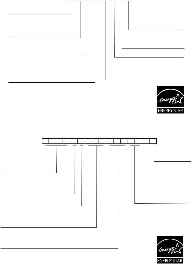
MODEL NUMBER NOMENCLATURE 581B036-150 (High Efficiency) — 3 to 121/2 Tons
581B E V 060 120 N DA
581B – Single Package
High-Efficiency
Gas/Electric Unit
Voltage Designation
E – 460-3-60
J – 208/230-1-60
P – 208/230-3-60
T – 575-3-60
Fuel Control Type/Heat Exchanger
V – Natural Gas/Direct Spark Ignition
Nominal Tons |
|
||
036 – |
3 |
090 |
– 7-1/2 |
048 – |
4 |
102 |
– 8-1/2 |
060 – |
5 |
120 |
– 10 |
072 – |
6 |
150 |
– 12-1/2 |
*Refer to the Trade Prices for ordering codes of factory-installed options.
Factory-Installed Options*
Gas Heat Options
A – Standard
N – Low NOx Unit
S – Stainless Steel Heat Exchanger
Gas Heat Input (Btuh) |
|
|
|
|||
072 |
– |
72,000 |
180 |
– |
180,000 |
|
115 |
– |
115,000 |
224 |
– |
224,000 |
|
125 |
– |
125,000 |
250 |
– |
250,000 |
|
150 |
– |
150,000 |
|
|
|
|
Low NOx |
California Compliant 3 Phase |
|||||
060 |
– |
60,000 |
071 |
– |
72,000 |
|
090 |
– |
90,000 |
114 – |
115,000 |
a48-8191 |
|
120 |
– |
120,000 |
149 |
– |
150,000 |
|
The Example model number 581BEV060120NDA designates a high efficiency 5-ton 460-3-60 volt Low NOx gas/electric roof top unit with 120,000 Btuh natural gas heat and EconoMi$er IV. Low NOx units must show an “N” in the nomenclature.
5
MODEL NUMBER NOMENCLATURE — 579F180-300
579F E V 180 230 – – C B
579F – Single-Package
Standard-Efficiency Gas/Electric Unit
Voltage Designation
E – 460-3-60
P – 208/230-3-60
T – 575-3-60
Fuel and Control Type
V – Natural Gas/Electric Relight Pilot
Nominal Tons
180 – 15 Tons
216 – 18 Tons
240 – 20 Tons
300 – 25 Tons
NOTES:
Fan Drive Option
(Standard Motor)
B – Standard Low-Medium
Fan Drive Static
Capability
D – Alternate High Fan
Drive Static Capability
Factory-Installed Outdoor-Air
and Other Upgrade Options
C – EconoMi$er IV
H – Manual Outdoor-Air Damper
Design Series Code
Gas Heat Input (Btuh) |
|
||
230 |
– 230,000 |
|
|
275 |
– 275,000 |
|
|
300 |
– 300,000 |
a48-8192 |
|
360 |
– 360,000 |
||
|
|||
1.All indoor-fan motors 5 hp and larger meet the minimum efficiency requirements as established by the Energy Policy Act of 1992 (EPACT) effective October 24, 1997.
2.The example model number 579FEV180230--CB designates a 15-ton 460-3-60 volt gas/ electric rooftop unit with 230,000 Btuh natural gas heat input, EconoMi$er IV, and the standard low-medium fan drive static capability.
MODEL NUMBER NOMENCLATURE 580F180-300
580F E V 180 275 – – C B
580F – Single Package
Medium-Efficiency Gas/Electric Unit
Voltage Designation
E – 460-3-60
P – 208/230-3-60
T – 575-3-60
Fuel and Control Type
V – Natural Gas/Electric Relight Pilot
Nominal Tons
180 – 15 Tons
210 – 18 Tons
240 – 20 Tons
300 – 25 Tons
Fan Drive Position
(Standard Motor)
B – Standard Low-Medium
Fan Drive Static
Capability
D– Alternate High Fan Drive Static Capability
Factory-Installed Outdoor-Air
and Other Upgrade Options
C – EconoMi$er IV
H – Manual Outdoor-Air Damper
Design Series Change
Gas Heat Input (Btuh) |
|
||
275 |
– 275,000 |
|
|
300 |
– |
300,000 |
a48-8193 |
360 |
– |
360,000 |
|
NOTES:
1.All indoor-fan motors 5 hp and larger meet the minimum efficiency requirements as established by the Energy Policy Act of 1992 (EPACT) effective October 24, 1997.
2.The example model number 580FEV180275--CB designates a 15-ton 460-3-60 volt gas/ electric rooftop unit with 275,000 Btuh natural gas heat input, EconoMi$er IV, and the standard low-medium fan drive static capability.
6
MODEL NUMBER NOMENCLATURE 581A155, 180, 181 — 13 to 15 Tons
581A E |
V 180 230 – – C B |
|
581A – Single Package |
Fan Drive Position |
|
High Efficiency Gas/Electric Unit |
(Standard Motor) |
|
|
B – Standard Low-Medium |
|
|
Fan Drive Static |
|
|
Capability |
|
Voltage Designation |
D – Alternate High Fan |
|
Drive Static Capability |
|
|
E – 460-3-60 |
|
|
|
|
|
P – 208/230-3-60 |
|
|
T – 575-3-60 |
Factory-Installed Outdoor-Air |
|
|
||
|
and Other Upgrade Options |
|
|
C – EconoMi$er IV |
|
|
H – Manual Outdoor-Air Damper |
|
Fuel and Control Type |
|
|
V – Natural Gas/Electric Relight Pilot |
Design Series Change |
|
|
|
|
|
Gas Heat Input (Btuh) |
|
Nominal Tons |
230 – 230,000 |
|
275 – 275,000 |
a48-8194 |
|
155 – 13 Tons |
300 – 300,000 |
|
180 – 15 Tons |
360 – 360,000 |
|
181 – 15 Tons with hot gas reheat* |
|
|
*See pages 213 and 214 for cooling capacity tables for 5581A181 unit. For all other data, contact application engineering.
NOTE: All indoor-fan motors 5 hp and larger meet the minimum efficiency requirements as established by the Energy Policy Act of 1992 (EPACT) effective October 24, 1997.
The example model number: 581AEV180230--CB designates a 15 ton 460-3-60 high efficiency gas/electric rooftop unit with 230,000 Btuh natural gas input, EconoMi$er IV and standard, low-medium fan drive static capability.
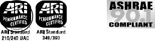
MODEL NUMBER NOMENCLATURE 581A210-300 — 18 to 25 Tons
5 8 1 A E A 2 1 0 2 5 0 – – A A
|
|
|
|
|
|
|
Factory-Installed |
581A – High Efficiency Rooftop |
|
|
|
|
|
Options* |
|
|
|
|
|
|
|
||
Units Gas Heating/ |
|
|
|
|
|
|
|
Electric Cooling |
|
|
|
|
|
|
|
Constant Volume |
|
|
|
|
|
|
|
Voltage Designation |
|
|
|
|
Coil Protection Options* |
||
|
|
|
|
|
|
|
|
E – 460-3-60 |
|
|
|
|
|
|
|
P – 208/230-3-60 |
|
|
|
|
|
|
|
T – 575-3-60 |
|
|
|
|
|
|
|
Indoor Fan, Orientation, Hinged Doors |
Design Series Code |
||||||
Return/Supply Smoke Detector Options* |
|
|
|
|
|
|
|
Nominal Cooling Capacity |
|
|
|
|
|
|
|
210 – 18 Tons |
|
|
|
|
|
|
a48-8208 |
240 – 20 Tons |
|
|
|
|
|
|
|
300 – 25 Tons |
|
|
|
|
|
|
|
Gas Heat Input (Btuh) |
|
|
|
|
|
|
|
250 – 250,000 |
25S-- 250,000 w/SS Heat Exchanger |
|
|
|
|
|
|
365 – 365,000 |
36S-- 365,000 w/SS Heat Exchanger |
|
|
|
|
|
|
400 – 400,000 |
40S-- 400,000 w/SS Heat Exchanger |
|
|
|
|
|
|
SS — Stainless Steel *Refer to unit price pages.
7
ARI* CAPACITY RATINGS — 580F036-151
|
|
NOMINAL |
STANDARD |
|
NET COOLING |
TOTAL |
|
|
|
SEER† |
|
SOUND |
|||||
UNIT 580F |
|
CAPACITY |
|
|
|
|
|
|
|
RATING |
|||||||
TONS |
CFM |
|
|
kW |
|
Belt Drive |
|
Direct Drive |
|
||||||||
|
|
|
(Btuh) |
|
|
|
|
(dB) |
|||||||||
|
|
|
|
|
|
|
|
|
|
|
|
|
|
|
|||
036 |
|
3 |
|
1200 |
|
35,000 |
4.0 |
|
10.0 |
|
|
9.7 |
|
81 |
|||
048 |
|
4 |
|
1600 |
|
47,000 |
5.3 |
|
10.0 |
|
|
9.7 |
|
81 |
|||
060 |
|
5 |
|
2000 |
|
57,000 |
6.7 |
|
10.0 |
|
|
9.7 |
|
81 |
|||
|
|
|
|
|
|
|
|
|
|
|
|
|
|
|
|
||
UNIT |
|
NOMINAL |
|
NET COOLING |
|
TOTAL |
|
|
|
|
|
SOUND |
|
|
|
||
|
|
CAPACITY |
|
|
|
EER |
|
RATING |
|
IPLV |
|||||||
580F |
|
TONS |
|
|
kW |
|
|
|
|
||||||||
|
|
(Btuh) |
|
|
|
|
|
|
|
(dB) |
|
|
|
||||
|
|
|
|
|
|
|
|
|
|
|
|
|
|
|
|||
072 |
|
6 |
|
72,000 |
|
|
8.0 |
|
|
9.0 |
|
81 |
|
** |
|||
073 |
|
6 |
|
71,000 |
|
|
7.0 |
|
|
10.1 |
|
80 |
|
** |
|||
090 |
|
71/2 |
|
85,000 |
|
|
9.6 |
|
|
8.9 |
|
87 |
|
9.40 |
|||
091 |
|
71/2 |
|
88,000 |
|
|
8.7 |
|
|
10.1 |
|
82 |
|
10.5 |
|||
103 |
|
81/2 |
|
100,000 |
|
|
9.9 |
|
|
10.1 |
|
82 |
|
10.4 |
|||
120 |
|
10 |
|
117,000 |
|
|
13.0 |
|
|
9.0 |
|
88 |
|
9.40 |
|||
121 |
|
10 |
|
114,000 |
|
|
11.3 |
|
|
10.1 |
|
84 |
|
11.0 |
|||
150 |
|
121/2 |
|
144,000 |
|
|
16.0 |
|
|
9.0 |
|
87 |
|
9.20 |
|||
151 |
|
121/2 |
|
136,000 |
|
|
14.3 |
|
|
9.5 |
|
86 |
|
9.70 |
|||
|
|
LEGEND |
dB |
— |
Sound Levels (decibels) |
db |
— |
Dry Bulb |
EER |
— |
Energy Efficiency Ratio |
IPLV |
— |
Integrated Part-Load Values |
SEER — |
Seasonal Energy Efficiency Ratio |
|
wb |
— |
Wet Bulb |
*Air Conditioning and Refrigeration Institute.
†Applies only to units with capacity of 65,000 Btuh or less. **The IPLV applies only to two-stage cooling units.
NOTES:
1.Rated in accordance with ARI Standards 210/240 (for sizes 036120) or 360, (for size 150 and 151) and 270.
2.ARI ratings are net values, reflecting the effects of circulating fan heat.
3.Ratings are based on:
Cooling Standard: 80 F db, 67 F wb indoor entering-air temperature and 95 F db air entering outdoor unit.
IPLV Standard: 80 F db, 67 F wb indoor entering-air temperature and 80 F db outdoor entering-air temperature.
4.All 580F036, 048, 060, 073, 091, 103, 121, 151 units are in compliance with ASHRAE 90.1-1999 Energy Standard for minimum SEER and EER requirements. Refer to state and local codes or visit the following website: http://solstice.crest.org/efficiency/bcap to determine if compliance with this standard pertains to a given geographical area of the United States.
5.All 581B036-120 units are in compliance with Energy Star high efficiency requirements.
HEATING CAPACITIES AND EFFICIENCIES (Standard-Efficiency Units) — 580F036-151
208/230-1-60 — SINGLE-STAGE GAS HEAT
UNIT |
INPUT |
OUTPUT |
TEMPERATURE |
MINIMUM HEATING |
|
EFFICIENCY |
|
580F |
CAPACITY |
CAPACITY |
RISE (°F) |
AIRFLOW (CFM) |
AFUE (%) |
|
Steady State (%) |
036074 |
74,000 |
57,000 |
25-55 |
1004 |
80 |
|
80 |
036115 |
115,000 |
89,000 |
55-85 |
1002 |
80 |
|
80 |
048074 |
74,000 |
57,000 |
25-55 |
1004 |
80 |
|
80 |
048115 |
115,000 |
91,000 |
35-65 |
1327 |
80 |
|
80 |
048150 |
150,000 |
118,000 |
50-80 |
1396 |
80 |
|
80 |
060074 |
74,000 |
57,000 |
25-55 |
1004 |
80 |
|
80 |
060115 |
115,000 |
91,000 |
35-65 |
1327 |
80 |
|
80 |
060150 |
150,000 |
118,000 |
50-80 |
1314 |
80 |
|
80 |
208/230-1-60 — SINGLE-STAGE GAS HEAT — LOW NOx
UNIT |
INPUT |
OUTPUT |
TEMPERATURE |
MINIMUM HEATING |
|
EFFICIENCY |
|
580F |
CAPACITY |
CAPACITY |
RISE (°F) |
AIRFLOW (CFM) |
AFUE (%) |
|
Steady State (%) |
036060N |
60,000 |
49,000 |
20-50 |
910 |
80 |
|
80 |
036090N |
90,000 |
73,000 |
30-60 |
1130 |
80 |
|
80 |
048060N |
60,000 |
49,000 |
20-50 |
910 |
80 |
|
80 |
048090N |
90,000 |
73,000 |
30-60 |
1130 |
80 |
|
80 |
048120N |
120,000 |
98,000 |
40-70 |
1300 |
80 |
|
80 |
060060N |
60,000 |
49,000 |
20-50 |
910 |
80 |
|
80 |
060090N |
90,000 |
73,000 |
30-60 |
1130 |
80 |
|
80 |
060120N |
120,000 |
98,000 |
40-70 |
1300 |
80 |
|
80 |
8
ARI* CAPACITY RATINGS (cont)
HEATING CAPACITIES AND EFFICIENCIES (Standard Efficiency Units) — 580F036-151 (cont)
208/230/460-3-60 — SINGLE-STAGE GAS HEAT — LOW NOx
UNIT |
INPUT |
OUTPUT |
TEMPERATURE |
MINIMUM HEATING |
|
EFFICIENCY |
|
580F |
CAPACITY |
CAPACITY |
RISE (°F) |
AIRFLOW (CFM) |
AFUE (%) |
|
Steady State (%) |
036060N |
60,000 |
49,000 |
20-50 |
910 |
80 |
|
80 |
036090N |
90,000 |
73,000 |
30-60 |
1130 |
80 |
|
80 |
048060N |
60,000 |
49,000 |
20-50 |
910 |
80 |
|
80 |
048090N |
90,000 |
73,000 |
30-60 |
1130 |
80 |
|
80 |
048120N |
120,000 |
98,000 |
40-70 |
1300 |
80 |
|
80 |
060060N |
60,000 |
47,000 |
20-50 |
910 |
80 |
|
80 |
060090N |
90,000 |
73,000 |
30-60 |
1130 |
80 |
|
80 |
060120N |
120,000 |
98,000 |
40-70 |
1300 |
80 |
|
80 |
208/230, 460, 575-3-60 — 2-STAGE GAS HEAT
UNIT |
INPUT CAPACITY |
OUTPUT CAPACITY |
TEMPERATURE |
MINIMUM HEATING |
EFFICIENCY |
|||
580F |
1st Stage |
2nd Stage |
1st Stage |
2nd Stage |
RISE (°F) |
AIRFLOW (CFM) |
AFUE (%) |
Steady State (%) |
036115 |
82,000 |
115,000 |
65,600 |
92,000 |
55-85 |
1004 |
80 |
80 |
048150 |
120,000 |
150,000 |
96,000 |
120,000 |
50-80 |
1396 |
80 |
80 |
060150 |
120,000 |
150,000 |
96,000 |
120,000 |
50-80 |
1314 |
80 |
80 |
072150 |
120,000 |
150,000 |
96,000 |
120,000 |
50-80 |
1390 |
80 |
80 |
090180 |
120,000 |
180,000 |
96,000 |
144,000 |
35-65 |
2060 |
80 |
80 |
090224 |
180,000 |
224,000 |
144,000 |
179,200 |
45-75 |
2230 |
80 |
80 |
120180 |
120,000 |
180,000 |
90,000 |
144,000 |
35-65 |
2060 |
80 |
80 |
120224 |
180,000 |
224,000 |
144,000 |
179,200 |
35-65 |
2510 |
80 |
80 |
120250 |
200,000 |
250,000 |
160,000 |
200,000 |
40-70 |
2650 |
80 |
80 |
150224 |
180,000 |
224,000 |
144,000 |
179,200 |
35-65 |
2510 |
80 |
80 |
150250 |
200,000 |
250,000 |
160,000 |
200,000 |
40-70 |
2650 |
80 |
80 |
208/230, 460, 575-3-60 — SINGLE-STAGE GAS HEAT
UNIT |
INPUT |
OUTPUT |
TEMPERATURE |
MINIMUM HEATING |
EFFICIENCY |
|
580F |
CAPACITY |
CAPACITY |
(°F) |
AIRFLOW (CFM) |
AFUE (%) |
Steady State (%) |
036074 |
74,000 |
59,200 |
15-45 |
1220 |
80 |
80 |
048074 |
74,000 |
59,200 |
15-45 |
1220 |
80 |
80 |
048115 |
115,000 |
92,000 |
35-65 |
1320 |
80 |
80 |
060074 |
74,000 |
59,200 |
15-45 |
1220 |
80 |
80 |
060115 |
115,000 |
92,000 |
35-65 |
1320 |
80 |
80 |
072074 |
74,000 |
59,200 |
15-45 |
1220 |
80 |
80 |
072115 |
115,000 |
92,000 |
35-65 |
1320 |
80 |
80 |
090125, 091125 |
125,000 |
100,000 |
20-50 |
1860 |
80 |
80 |
103125 |
125,000 |
100,000 |
20-50 |
1860 |
80 |
80 |
LEGEND
AFUE — Annual Fuel Utilization Efficiency
HEATING CAPACITIES AND EFFICIENCIES (Medium-Efficiency Units) — 580F036-151
UNIT |
HEATING INPUT (Btuh) |
OUTPUT CAPACITY |
TEMPERATURE |
MINIMUM HEATING |
AFUE |
STEADY-STATE |
580F |
Stage 2/Stage 1 |
(Btuh) |
RISE (F) |
AIRFLOW (CFM) |
(%) |
EFFICIENCY (%) |
073074 |
—/ 74,000 |
59,200 |
25-55 |
1220 |
80.0 |
80.0 |
073115 |
—/115,000 |
92,000 |
35-65 |
1320 |
80.0 |
80.0 |
073150 |
150,000/120,000 |
120,000 |
50-80 |
1390 |
80.0 |
80.0 |
091125 |
—/125,000 |
100,000 |
20-50 |
1860 |
80.0 |
80.0 |
091180 |
180,000/120,000 |
144,000 |
35-65 |
2060 |
80.0 |
80.0 |
091224 |
224,000/180,000 |
179,200 |
45-75 |
2180 |
80.0 |
80.0 |
103125 |
—/125,000 |
100,000 |
20-50 |
1860 |
80.0 |
80.0 |
103180 |
180,000/120,000 |
144,000 |
35-65 |
2060 |
80.0 |
80.0 |
103224 |
224,000/180,000 |
179,200 |
45-75 |
2180 |
80.0 |
80.0 |
121180 |
180,000/120,000 |
144,000 |
35-65 |
2060 |
80.0 |
80.0 |
121224 |
224,000/180,000 |
179,200 |
35-65 |
2510 |
80.0 |
80.0 |
121250 |
250,000/200,000 |
200,000 |
40-70 |
2650 |
80.0 |
80.0 |
151224 |
224,000/180,000 |
179,200 |
35-65 |
2510 |
80.0 |
80.0 |
151250 |
250,000/200,000 |
200,000 |
40-70 |
2650 |
80.0 |
80.0 |
9
ARI* CAPACITY RATINGS — 581B036-150
UNIT |
NOMINAL |
COOLING |
TOTAL |
SEER† |
EER |
SOUND RATING |
IPLV |
|
581B |
TONS |
(Btuh) |
kW |
dB |
||||
|
|
|
||||||
036 |
3 |
36,000 |
3.21 |
13.0 |
11.20 |
76 |
** |
|
048 |
4 |
46,000 |
4.25 |
13.0 |
11.05 |
76 |
** |
|
060 |
5 |
61,000 |
5.55 |
13.0 |
11.00 |
80 |
** |
|
072 |
6 |
73,000 |
6.70 |
— |
11.00 |
80 |
** |
|
090 |
71/2 |
90,000 |
8.18 |
— |
11.00 |
82 |
11.6 |
|
102 |
81/2 |
103,000 |
8.90 |
— |
11.60 |
82 |
12.8 |
|
120 |
10 |
120,000 |
10.91 |
— |
11.00 |
84 |
11.4 |
|
150 |
121/2 |
138,000 |
14.40 |
— |
9.6 |
86 |
10.3 |
LEGEND
EER — Energy Efficiency Ratio
IPLV — Integrated Part-Load Value
SEER — Seasonal Energy Efficiency Ratio
*Air-Conditioning & Refrigeration Institute.
†Applies only to units with capacity of 65,000 Btuh or less. **The IPLV is not applicable to single-compressor units.
NOTES:
1.Rated in accordance with ARI Standard 210/240 (036-120 units) or 360 (150 units) and 270 (036-150 units).
2.Ratings are net values, reflecting the effects of circulating fan heat. Ratings are based on:
Cooling Standard: 80 F db, 67 wb indoor entering-air temperature and 95 F db outdoor entering-air temperature.
IPLV Standard: 80 F db, 67 F wb indoor entering-air temperature and 80 F db outdoor entering-air temperature.
|
|
|
|
Sizes 036-120 |
Sizes 150 |
||
|
Only |
|
Only |
3.All 581B036-150 units are in compliance with ASHRAE 90.1-1999 Energy Standard for minimum SEER and EER requirements. Refer to state and local codes or visit the following website: http://solstice.crest.org/efficiency/bcap to determine if compliance with this standard pertains to a given geographical area of the United States.
4.All 581B036-120 units are Energy Star certified.
HEATING CAPACITIES AND EFFICIENCIES — 581B036-150
208/230-1-60 — SINGLE-STAGE GAS HEAT
UNIT |
INPUT CAPACITY |
OUTPUT CAPACITY |
TEMPERATURE |
MINIMUM HEATING |
EFFICIENCY |
||
581B |
RISE (°F) |
AIRFLOW (CFM) |
AFUE (%) |
Steady State (%) |
|||
|
|
||||||
036072 |
72,000 |
58,000 |
25-55 |
1004 |
82.8 |
82.0 |
|
036115 |
115,000 |
90,000 |
55-85 |
1002 |
80.0 |
80.0 |
|
048072 |
72,000 |
58,000 |
25-55 |
1004 |
82.8 |
82.0 |
|
048115 |
115,000 |
90,000 |
35-65 |
1320 |
81.0 |
81.0 |
|
048150 |
150,000 |
118,000 |
50-80 |
1396 |
80.4 |
80.0 |
|
060072 |
72,000 |
58,000 |
25-55 |
1004 |
82.8 |
82.0 |
|
060115 |
115,000 |
92,000 |
35-65 |
1327 |
81.0 |
81.0 |
|
060150 |
150,000 |
118,000 |
50-80 |
1314 |
80.4 |
80.0 |
|
|
LEGEND |
|
|
|
|
|
|
AFUE — Annual Fuel Utilization Efficiency. |
|
|
|
|
|||
|
|
208/230-1-60 — SINGLE-STAGE GAS HEAT — LOW NOx |
|
|
|||
|
|
|
|
|
|
||
UNIT |
INPUT CAPACITY |
OUTPUT CAPACITY |
TEMPERATURE |
MINIMUM HEATING |
EFFICIENCY |
||
581B |
RISE (°F) |
AIRFLOW (CFM) |
AFUE (%) |
Steady State (%) |
|||
|
|
||||||
036060N |
60,000 |
50,000 |
20-50 |
930 |
80.2 |
81.2 |
|
036090N |
90,000 |
74,000 |
30-60 |
1150 |
81.0 |
81.4 |
|
048060N |
60,000 |
50,000 |
20-50 |
930 |
80.2 |
81.2 |
|
048090N |
90,000 |
74,000 |
30-60 |
1150 |
81.0 |
81.4 |
|
048120N |
120,000 |
101,000 |
40-70 |
1340 |
80.7 |
82.4 |
|
060060N |
60,000 |
50,000 |
20-50 |
930 |
80.2 |
81.2 |
|
060090N |
90,000 |
74,000 |
30-60 |
1150 |
81.0 |
81.4 |
|
060120N |
120,000 |
101,000 |
40-70 |
1340 |
80.7 |
82.4 |
|
LEGEND
AFUE — Annual Fuel Utilization Efficiency.
10
ARI* CAPACITY RATINGS (cont)
HEATING CAPACITIES AND EFFICIENCIES — 581B036-150(cont)
208/230/460-3-60 — SINGLE-STAGE GAS HEAT — LOW NOx
UNIT |
|
INPUT CAPACITY |
|
OUTPUT CAPACITY |
|
TEMPERATURE |
|
MINIMUM HEATING |
|
EFFICIENCY |
||||||||||
581B |
|
|
|
|
RISE (°F) |
|
|
AIRFLOW (CFM) |
|
AFUE (%) |
|
Steady State (%) |
||||||||
|
|
|
|
|
|
|
|
|
|
|
|
|
||||||||
036060N |
60,000 |
|
|
|
50,000 |
|
|
|
|
20-50 |
|
|
930 |
|
80.2 |
81.2 |
||||
036090N |
90,000 |
|
|
|
74,000 |
|
|
|
|
30-60 |
|
|
1150 |
|
81.0 |
81.4 |
||||
048060N |
60,000 |
|
|
|
50,000 |
|
|
|
|
20-50 |
|
|
930 |
|
80.2 |
81.2 |
||||
048090N |
90,000 |
|
|
|
74,000 |
|
|
|
|
30-60 |
|
|
1150 |
|
81.0 |
81.4 |
||||
048120N |
120,000 |
|
|
|
101,000 |
|
|
|
|
40-70 |
|
|
1340 |
|
80.7 |
82.4 |
||||
060060N |
60,000 |
|
|
|
50,000 |
|
|
|
|
20-50 |
|
|
930 |
|
80.2 |
81.2 |
||||
060090N |
90,000 |
|
|
|
74,000 |
|
|
|
|
30-60 |
|
|
1150 |
|
81.0 |
81.4 |
||||
060120N |
120,000 |
|
|
|
101,000 |
|
|
|
|
40-70 |
|
|
1340 |
|
80.7 |
82.4 |
||||
|
|
|
|
|
|
208/230/460-3-60 — SINGLE-STAGE GAS HEAT |
|
|
|
|||||||||||
|
|
|
|
|
|
|
(California Compliant Models) |
|
|
|
||||||||||
|
|
|
|
|
|
|
|
|
|
|
|
|
|
|
||||||
UNIT |
|
INPUT CAPACITY |
|
OUTPUT CAPACITY |
|
TEMPERATURE |
|
MINIMUM HEATING |
|
EFFICIENCY |
||||||||||
581B |
|
|
|
|
RISE (°F) |
|
|
AIRFLOW (CFM) |
|
AFUE (%) |
|
Steady State (%) |
||||||||
|
|
|
|
|
|
|
|
|
|
|
|
|
||||||||
036071 |
72,000 |
|
|
|
59,040 |
|
|
|
|
25-55 |
|
|
1000 |
|
82.0 |
82.0 |
||||
036114 |
115,000 |
|
|
|
93,150 |
|
|
|
|
55-85 |
|
|
1020 |
|
80.0 |
80.0 |
||||
048071 |
72,000 |
|
|
|
59,040 |
|
|
|
|
25-55 |
|
|
1000 |
|
82.0 |
82.0 |
||||
048114 |
115,000 |
|
|
|
93,150 |
|
|
|
|
30-60 |
|
|
1440 |
|
81.0 |
81.0 |
||||
048149 |
150,000 |
|
|
|
120,000 |
|
|
|
|
50-80 |
|
|
1390 |
|
80.0 |
80.0 |
||||
060071 |
72,000 |
|
|
|
59,040 |
|
|
|
|
25-55 |
|
|
1220 |
|
82.0 |
82.0 |
||||
060114 |
115,000 |
|
|
|
93,150 |
|
|
|
|
35-65 |
|
|
1330 |
|
81.0 |
81.0 |
||||
060149 |
150,000 |
|
|
|
120,000 |
|
|
|
|
50-80 |
|
|
1390 |
|
80.0 |
80.0 |
||||
|
|
|
|
|
|
208/230/460-3-60 — 2-STAGE GAS HEAT |
|
|
|
|||||||||||
|
|
|
|
|
|
|
|
|
|
|
|
|
|
|||||||
UNIT |
|
INPUT CAPACITY |
|
OUTPUT CAPACITY |
|
|
TEMPERATUR |
|
MINIMUM |
EFFICIENCY |
||||||||||
581B |
|
1st Stage |
2nd Stage |
1st Stage |
2nd Stage |
|
E |
|
|
HEATING |
AFUE (%) |
|
Steady State (%) |
|||||||
|
|
RISE (°F) |
|
|
AIRFLOW (CFM) |
|
||||||||||||||
|
|
|
|
|
|
|
|
|
|
|
|
|
|
|
|
|
||||
036072 |
|
50,000 |
72,000 |
41,000 |
|
59,040 |
|
|
25-55 |
|
|
|
1004 |
|
82.8 |
|
82.0 |
|||
036115 |
|
82,000 |
115,000 |
65,600 |
|
93,150 |
|
|
55-85 |
|
|
|
1002 |
|
80.0 |
|
80.0 |
|||
048072 |
|
50,000 |
72,000 |
41,000 |
|
59,040 |
|
|
25-55 |
|
|
|
1004 |
|
82.8 |
|
82.0 |
|||
048115 |
|
82,000 |
115,000 |
66,420 |
|
93,150 |
|
|
35-65 |
|
|
|
1330 |
|
81.0 |
|
81.0 |
|||
048150 |
|
120,000 |
150,000 |
96,000 |
|
120,000 |
|
|
50-80 |
|
|
|
1390 |
|
80.4 |
|
80.0 |
|||
060072 |
|
50,000 |
72,000 |
41,000 |
|
59,040 |
|
|
25-55 |
|
|
|
1004 |
|
82.8 |
|
82.0 |
|||
060115 |
|
82,000 |
115,000 |
66,420 |
|
93,150 |
|
|
35-65 |
|
|
|
1330 |
|
81.0 |
|
81.0 |
|||
060150 |
|
120,000 |
150,000 |
96,000 |
|
120,000 |
|
|
50-80 |
|
|
|
1370 |
|
80.4 |
|
80.0 |
|||
072072 |
|
50,000 |
72,000 |
41,000 |
|
59,040 |
|
|
25-55 |
|
|
|
1220 |
|
82.0 |
|
82.0 |
|||
072115 |
|
82,000 |
115,000 |
66,420 |
|
93,150 |
|
|
35-65 |
|
|
|
1330 |
|
81.0 |
|
81.0 |
|||
072150 |
|
120,000 |
150,000 |
96,000 |
|
120,000 |
|
|
50-80 |
|
|
|
1390 |
|
80.0 |
|
80.0 |
|||
090125 |
|
90,000 |
125,000 |
73,800 |
|
102,500 |
|
|
20-50 |
|
|
|
1900 |
|
82.0 |
|
82.0 |
|||
090180 |
|
120,000 |
180,000 |
98,400 |
|
147,600 |
|
|
35-65 |
|
|
|
1440 |
|
82.0 |
|
82.0 |
|||
090224 |
|
180,000 |
224,000 |
147,600 |
|
183,680 |
|
|
45-75 |
|
|
|
2230 |
|
82.0 |
|
82.0 |
|||
102125 |
|
90,000 |
125,000 |
73,800 |
|
102,500 |
|
|
20-50 |
|
|
|
1900 |
|
82.0 |
|
82.0 |
|||
102180 |
|
120,000 |
180,000 |
98,400 |
|
147,600 |
|
|
35-65 |
|
|
|
1440 |
|
82.0 |
|
82.0 |
|||
102224 |
|
180,000 |
224,000 |
147,600 |
|
183,680 |
|
|
45-75 |
|
|
|
2230 |
|
82.0 |
|
82.0 |
|||
120180 |
|
120,000 |
180,000 |
98,400 |
|
147,600 |
|
|
35-65 |
|
|
|
1440 |
|
82.0 |
|
82.0 |
|||
120224 |
|
180,000 |
224,000 |
147,600 |
|
183,680 |
|
|
35-65 |
|
|
|
2570 |
|
82.0 |
|
82.0 |
|||
120250 |
|
200,000 |
250,000 |
160,000 |
|
200,000 |
|
|
40-70 |
|
|
|
2650 |
|
80.0 |
|
80.0 |
|||
150224 |
|
180,000 |
224,000 |
147,600 |
|
183,680 |
|
|
35-65 |
|
|
|
2570 |
|
82.0 |
|
82.0 |
|||
150250 |
|
200,000 |
250,000 |
160,000 |
|
200,000 |
|
|
40-70 |
|
|
|
2650 |
|
80.0 |
|
80.0 |
|||
LEGEND
AFUE — Annual Fuel Utilization Efficiency
NOTE: Capacities for stainless steel heat exchanger units are the same as standard units.
11

ARI* CAPACITY RATINGS — 579F180-300
LOW HEAT UNITS
UNIT |
NOMINAL |
NET COOLING |
|
TOTAL |
|
SOUND |
|
CAPACITY |
|
EER |
RATING |
IPLV |
|||
579F |
TONS |
|
WATTS |
||||
(Btuh) |
|
|
(dB) |
|
|||
|
|
|
|
|
|
||
180 |
15 |
174,000 |
20,128 |
8.6 |
88 |
9.3 |
|
216 |
18 |
188,000 |
21,619 |
8.7 |
88 |
9.5 |
|
240 |
20 |
220,000 |
25,513 |
8.6 |
94 |
8.7 |
|
300 |
25 |
268,000 |
31,068 |
8.6 |
94 |
9.2 |
|
|
|
HIGH HEAT UNITS |
|
|
|
||
|
|
|
|
|
|
|
|
UNIT |
NOMINAL |
NET COOLING |
|
TOTAL |
|
SOUND |
|
CAPACITY |
|
EER |
RATING |
IPLV |
|||
579F |
TONS |
|
WATTS |
||||
(Btuh) |
|
|
(dB) |
|
|||
|
|
|
|
|
|
||
180 |
15 |
174,000 |
|
20,154 |
8.6 |
88 |
9.3 |
216 |
18 |
186,000 |
|
21,798 |
8.5 |
88 |
9.3 |
240 |
20 |
218,000 |
|
25,719 |
8.5 |
94 |
8.5 |
300 |
25 |
268,000 |
|
31,600 |
8.5 |
94 |
8.9 |
|
LEGEND |
|
|
|
|
|
|
dB |
— Sound Levels (decibels) |
|
db |
— Dry Bulb |
|
EER — Energy Efficiency Ratio |
||
IPLV |
— |
Integrated Part-Load Values |
wb |
— |
Wet Bulb |
*Air Conditioning and Refrigeration Institute.
NOTES:
1.Rated in accordance with ARI Standards 360 and 270.
2.The 579F300 is beyond the scope of the ARI Certification Program.
3.ARI ratings are net values, reflecting the effects of circulating fan heat.
4.Ratings are based on:
Cooling Standard: 80 F db, 67 F wb indoor entering-air temperature and 95 F db air entering outdoor unit.
IPLV Standard: 80 F db, 67 F wb indoor entering-air temperature and 80 F db outdoor entering-air temperature.
HEATING CAPACITIES AND EFFICIENCIES — 579F180-300
UNIT |
HEATING INPUT |
OUTPUT CAPACITY |
TEMPERATURE |
STEADY-STATE |
MINIMUM |
|
(Btuh) |
||||||
579F |
(Btuh) |
RISE (F) |
EFFICIENCY (%) |
HEATING CFM |
||
Stage 2/Stage 1* |
||||||
|
|
|
|
|
||
180230 |
230,000/172,000 |
186,000 |
15-45 |
81.0 |
3830 |
|
180300 |
300,000/225,000 |
243,000 |
30-60 |
81.0 |
3750 |
|
216275 |
275,000/206,000 |
223,000 |
15-45 |
81.0 |
4580 |
|
216360 |
360,000/270,000 |
292,000 |
20-50 |
81.0 |
5400 |
|
240275 |
275,000/206,000 |
223,000 |
15-45 |
81.0 |
4580 |
|
240360 |
360,000/270,000 |
292,000 |
20-50 |
81.0 |
5400 |
|
300275 |
275,000/206,000 |
223,000 |
15-45 |
81.0 |
4580 |
|
300360 |
360,000/270,000 |
292,000 |
20-50 |
81.0 |
5400 |
*All units are 2-stage heat.
NOTE: Minimum allowable temperature of mixed-air entering the heat exchanger during first-stage heating is 45 F. There is no minimum mixed-air temperature limitation during second-stage heating. For entering-air temperatures below 45 F both stages of heat must be energized together to minimize condensation issues and ensure proper unit operation.
AIR QUANTITY LIMITS
UNIT 579F |
MINIMUM CFM |
MAXIMUM CFM |
180 |
4500 |
7,500 |
216 |
5400 |
9,000 |
240 |
6000 |
10,000 |
300 |
7000 |
11,250 |
LOW OUTDOOR TEMPERATURE
OPERATING LIMITS (F)
UNITS |
TEMPERATURE |
All |
40 |
180 and 216 with Low Ambient Kit |
10 |
240 and 300 with Low Ambient Kit |
25 |
All with Motormaster® Head Pressure Control |
–20 |
12

ARI* CAPACITY RATINGS — 580F180-300
UNIT SIZE |
NOMINAL |
NET COOLING |
TOTAL |
|
SOUND |
|
|
580F |
EER |
RATING |
IPLV |
||||
TONS |
CAPACITY (Btuh) |
WATTS |
|||||
(Low Heat) |
|
(dB) |
|
||||
|
|
|
|
|
|||
180 |
15 |
176,000 |
17,064 |
9.5 |
88 |
9.5 |
|
210 |
18 |
202,000 |
21,166 |
9.7 |
88 |
10.2 |
|
240 |
20 |
236,000 |
24,832 |
9.5 |
94 |
10.1 |
|
300 |
25 |
278,000 |
28,535 |
9.7 |
94 |
10.4 |
|
|
|
|
|
|
|
|
|
UNIT SIZE |
NOMINAL |
NET COOLING |
TOTAL |
|
SOUND |
|
|
580F |
EER |
RATING |
IPLV |
||||
TONS |
CAPACITY (Btuh) |
WATTS |
|||||
(High Heat) |
|
(dB) |
|
||||
|
|
|
|
|
|||
180 |
15 |
176,000 |
17,179 |
9.5 |
88 |
9.5 |
|
210 |
18 |
202,000 |
21,301 |
9.7 |
88 |
10.1 |
|
240 |
20 |
236,000 |
24,832 |
9.5 |
94 |
10.0 |
|
300 |
25 |
277,000 |
29,067 |
9.5 |
94 |
10.0 |
|
LEGEND |
Bels |
— Sound Levels (1 bel = 10 decibels) |
db |
— Dry Bulb |
EER — Energy Efficiency Ratio |
|
IPLV |
— Integrated Part-Load Values |
wb |
— Wet Bulb |
*Air Conditioning and Refrigeration Institute.
NOTES:
1.Rated in accordance with ARI Standards 360 and 270.
2.ARI ratings are net values, reflecting the effects of circulating fan heat.
3.Ratings are based on:
Cooling Standard: 80 F db, 67 F wb indoor entering-air temperature and 95 F db air entering outdoor unit.
IPLV Standard: 80 F db, 67 F wb indoor entering-air temperature and 80 F db outdoor entering-air temperature.
4.All 580F180-300 units are in compliance with ASHRAE 90.1- 1999 Energy Standard for minimum SEER and EER requirements. Refer to state and local codes or visit the following website: http://solstice.crest.org/efficiency/bcap to determine if compliance with this standard pertains to a given geographical area of the United States.
HEATING CAPACITIES AND EFFICIENCIES — 580F180-300
UNIT |
HEATING INPUT |
OUTPUT CAPACITY |
TEMPERATURE |
STEADY-STATE |
MINIMUM |
|
(Btuh) |
||||||
580F |
(Btuh) |
RISE (F) |
EFFICIENCY (%) |
HEATING CFM |
||
Stage 2/Stage 1* |
||||||
|
|
|
|
|
||
180275 |
275,000/206,000 |
223,000 |
15-45 |
81.0 |
3750 |
|
180360 |
360,000/270,000 |
292,000 |
20-50 |
81.0 |
3830 |
|
210275 |
275,000/206,000 |
223,000 |
15-45 |
81.0 |
4580 |
|
210360 |
360,000/270,000 |
292,000 |
20-50 |
81.0 |
5400 |
|
240275 |
275,000/206,000 |
223,000 |
15-45 |
81.0 |
4580 |
|
240360 |
360,000/270,000 |
292,000 |
20-50 |
81.0 |
5400 |
|
300275 |
275,000/206,000 |
223,000 |
15-45 |
81.0 |
4580 |
|
300360 |
360,000/270,000 |
292,000 |
20-50 |
81.0 |
5400 |
*All units are 2-stage heat.
NOTE: Minimum allowable temperature of mixed-air entering the heat exchanger during first-stage heating is 45 F. There is no minimum mixed-air temperature limitation during second-stage heating. For entering-air temperatures below 45 F both stages of heat must be energized together to minimize condensation issues and ensure proper unit operation.
AIR QUANTITY LIMITS (Cooling)
UNIT 580F |
MINIMUM CFM |
MAXIMUM CFM |
180 |
4500 |
7,500 |
210 |
5400 |
9,000 |
240 |
6000 |
10,000 |
300 |
7000 |
11,250 |
COOLING OPERATION
LOW OUTDOOR TEMPERATURE OPERATING LIMITS (F)
UNITS |
TEMPERATURE |
All — Standard Unit |
40 |
180 and 210 with Low Ambient Kit |
10 |
240 and 300 with Low Ambient Kit |
25 |
All with Motormaster® Head Pressure Control |
–20 |
13

ARI* CAPACITY RATINGS — 581A155,180
LOW HEAT UNITS
UNIT |
NOMINAL |
NET COOLING |
|
TOTAL |
|
SOUND |
|
CAPACITY |
|
EER |
RATING |
IPLV |
|||
581A |
TONS |
|
WATTS |
||||
(Btuh) |
|
|
(dB) |
|
|||
|
|
|
|
|
|
||
155230 |
13 |
134,000 |
|
12,209 |
10.60 |
88 |
11.4 |
180275 |
15 |
180,000 |
|
17,064 |
10.50 |
88 |
11.4 |
|
|
|
HIGH HEAT UNITS |
|
|
|
|
|
|
|
|
|
|
|
|
UNIT |
NOMINAL |
NET COOLING |
|
TOTAL |
|
SOUND |
|
CAPACITY |
|
EER |
RATING |
IPLV |
|||
581A |
TONS |
|
WATTS |
||||
(Btuh) |
|
|
(dB) |
|
|||
|
|
|
|
|
|
||
155300 |
13 |
134,000 |
|
12,218 |
10.60 |
88 |
11.4 |
180360 |
15 |
180,000 |
|
17,179 |
10.50 |
88 |
11.1 |
|
LEGEND |
dB |
— Sound Levels (decibels) |
db |
— Dry Bulb |
EER — Energy Efficiency Ratio |
|
IPLV |
— Integrated Part-Load Values |
wb |
— Wet Bulb |
*Air Conditioning and Refrigeration Institute.
NOTES:
1.Rated in accordance with ARI Standards 360 and 270.
2.ARI ratings are net values, reflecting the effects of circulating fan heat.
3.Ratings are based on:
Cooling Standard: 80 F db, 67 F wb indoor entering-air temperature and 95 F db air entering outdoor unit.
IPLV Standard: 80 F db, 67 F wb indoor entering-air temperature and 80 F db outdoor entering-air temperature.
4.All 581A155, 180 units are in compliance with ASHRAE 90.1- 1999 Energy Standard for minimum EER requirements. Refer to state and local codes or visit the following website: http://solstice.crest.org/efficiency/bcap to determine if compliance with this standard pertains to a given geographical area of the United States.
HEATING CAPACITIES AND EFFICIENCIES — 581A155-180
|
HEATING |
OUTPUT |
TEMPERATURE |
AGA STEADY |
MINIMUM HEATING |
|
UNIT 581A |
INPUT (Btuh) |
CAPACITY |
STATE |
|||
RISE (F) |
CFM† |
|||||
|
Stage 2/Stage 1* |
(Btuh) |
EFFICIENCY (%) |
|||
|
|
|
||||
155230 |
230,000/172,000 |
186,000 |
15-45 |
81.0 |
3750 |
|
155300 |
300,000/225,000 |
243,000 |
30-60 |
81.0 |
3830 |
|
180275 |
275,000/206,000 |
223,000 |
15-45 |
81.0 |
4580 |
|
180360 |
360,000/270,000 |
292,000 |
20-50 |
81.0 |
5400 |
*All units are 2-stage heat.
†Minimum heating cfm must be maintained to ensure proper heating operation.
NOTE: Minimum allowable temperature of mixed air entering the heat exchanger during first stage heating is 45 F. There is no minimum mixed-air limitation during second-stage heating. For entering air temperatures below 45 F, both stages of heat must be energized together to minimize condensation issues and ensure proper unit operation.
LOW OUTDOOR AIR TEMPERATURE
COOLING OPERATION LIMITS
|
|
TEMPERATURE LIMIT (F) |
||
UNIT SIZE |
Standard |
Unit With |
Unit With |
|
581A |
Motormaster® |
|||
Unit |
Low Ambient Kit |
|||
|
Control |
|||
|
|
|
||
155, 180 |
40 |
20 |
–20 |
|
AIR QUANTITY LIMITS (Cooling)
UNIT 581A |
MINIMUM CFM |
MAXIMUM CFM |
155 |
3900 |
6500 |
180 |
4500 |
7500 |
14

ARI* CAPACITY RATINGS — 581A210-300
UNIT |
NOMINAL |
CFM |
NET COOLING |
TOTAL |
EER |
SOUND RATING |
IPLV† |
|
581A |
TONS |
CAPACITY (Btuh) |
kW |
(dB) |
||||
|
|
|
||||||
210 |
18 |
5,500 |
200,000 |
18.5 |
10.8 |
81.7 |
12.0 |
|
240 |
20 |
6,000 |
234,000 |
21.7 |
10.8 |
81.7 |
11.9 |
|
300** |
25 |
7,500 |
278,000 |
27.8 |
10.0 |
84.6 |
10.9 |
|
|
LEGEND |
db |
— |
Dry Bulb |
EER — |
Energy Efficiency Ratio |
|
IPLV |
— |
Integrated Part-Load Values |
wb |
— |
Wet Bulb |
*Air Conditioning and Refrigeration Institute.
†IPLV values are calculated based on control configuration T.CTL = 2 (2 Stage Y1).
**Size 300 unit is not listed with ARI, but is tested to ARI standards.
NOTES:
1.Rated in accordance with ARI Standards 360-93 and 270-95.
2.ARI ratings are net values, reflecting the effects of circulating fan heat.
3.Ratings are based on:
Cooling Standard: 80 F db, 67 F wb indoor entering-air temperature and 95 F db air entering outdoor unit.
IPLV Standard: 80 F db, 67 F wb indoor entering-air temperature and 80 F db outdoor entering-air temperature.
4.All 581A210-300 units are in compliance with ASHRAE 90.1 2001 Energy Standard for minimum EER requirements. Refer to state and local codes or visit the following website: http://solstice.crest.org/efficiency/bcap to determine if compliance with this standard pertains to a given geographical area of the United States.
HEATING CAPACITIES AND EFFICIENCIES — 581A210-300
VERTICAL SUPPLY — NATURAL GAS
UNIT |
HEATING INPUT |
OUTPUT CAPACITY |
TEMPERATURE |
STEADY-STATE |
MINIMUM |
581A |
(Btuh) Stage 2/Stage 1 |
(Btuh) |
RISE (F) |
EFFICIENCY % |
HEATING CFM |
210250 |
250,000/199,000 |
205,000 |
15-45 |
82% |
4218 |
210365 |
365,000/281,000 |
296,000 |
25-55 |
81% |
4977 |
210400 |
400,000/317,000 |
328,000 |
25-55 |
82% |
5522 |
240250 |
250,000/199,000 |
205,000 |
15-45 |
82% |
4218 |
240365 |
365,000/281,000 |
296,000 |
25-55 |
81% |
4977 |
240400 |
400,000/317,000 |
328,000 |
25-55 |
82% |
5522 |
300250 |
250,000/199,000 |
205,000 |
15-45 |
82% |
4218 |
300365 |
365,000/281,000 |
296,000 |
25-55 |
81% |
4977 |
300400 |
400,000/317,000 |
328,000 |
25-55 |
82% |
5522 |
NOTE: All units are 2-stage gas heat.
HORIZONTAL SUPPLY — NATURAL GAS
UNIT |
HEATING INPUT |
OUTPUT CAPACITY |
TEMPERATURE |
STEADY-STATE |
MINIMUM |
581A |
(Btuh) Stage 2/Stage 1 |
(Btuh) |
RISE (F) |
EFFICIENCY % |
HEATING CFM |
210250 |
250,000/199,000 |
205,000 |
15-45 |
82% |
4218 |
210365 |
365,000/281,000 |
296,000 |
25-55 |
81% |
4977 |
210400 |
400,000/317,000 |
328,000 |
25-55 |
82% |
5522 |
240250 |
250,000/199,000 |
205,000 |
15-45 |
82% |
4218 |
240365 |
365,000/281,000 |
296,000 |
25-55 |
81% |
4977 |
240400 |
400,000/317,000 |
328,000 |
25-55 |
82% |
5522 |
300250 |
250,000/199,000 |
205,000 |
15-45 |
82% |
4218 |
300365 |
365,000/281,000 |
296,000 |
25-55 |
81% |
4977* |
300400 |
400,000/317,000 |
325,000 |
25-55 |
82% |
5522* |
*7000 cfm minimum recommended above 1.0 in. wg external static pressure.
NOTE: All units are 2-stage gas heat.
VERTICAL SUPPLY — PROPANE
UNIT |
HEATING INPUT |
OUTPUT CAPACITY |
TEMPERATURE |
STEADY-STATE |
MINIMUM |
581A |
(Btuh) Stage 2/Stage 1 |
(Btuh) |
RISE (F) |
EFFICIENCY % |
HEATING CFM |
210250 |
250,000/207,000 |
205,000 |
15-45 |
82% |
4218 |
210365 |
365,000/291,000 |
296,000 |
25-55 |
81% |
4480 |
210400 |
400,000/331,000 |
328,000 |
25-55 |
82% |
5522 |
240250 |
250,000/207,000 |
205,000 |
15-45 |
82% |
4218 |
240365 |
365,000/291,000 |
296,000 |
25-55 |
81% |
4480 |
240400 |
400,000/331,000 |
328,000 |
25-55 |
82% |
5522 |
300250 |
250,000/207,000 |
205,000 |
15-45 |
82% |
4218 |
300365 |
365,000/291,000 |
296,000 |
25-55 |
81% |
4480 |
300400 |
400,000/331,000 |
328,000 |
25-55 |
82% |
5522 |
NOTE: All units are 2-stage gas heat.
HORIZONTAL SUPPLY — PROPANE
UNIT |
HEATING INPUT |
OUTPUT CAPACITY |
TEMPERATURE |
STEADY-STATE |
MINIMUM |
581A |
(Btuh) Stage 2/Stage 1 |
(Btuh) |
RISE (F) |
EFFICIENCY % |
HEATING CFM |
210250 |
225,000/207,000 |
185,000 |
15-45 |
82% |
3807 |
210365 |
329,000/291,000 |
266,000 |
25-55 |
81% |
4480 |
210400 |
356,000/331,000 |
292,000 |
25-55 |
82% |
4916 |
240250 |
225,000/207,000 |
184,500 |
15-45 |
82% |
3796 |
240365 |
329,000/291,000 |
266,000 |
25-55 |
81% |
4480 |
240400 |
356,000/331,000 |
292,000 |
25-55 |
82% |
4916 |
300250 |
225,000/207,000 |
185,000 |
15-45 |
82% |
3807 |
300365 |
329,000/291,000 |
266,000 |
25-55 |
81% |
4480* |
300400 |
356,000/331,000 |
292,000 |
25-55 |
82% |
4920* |
*7000 cfm minimum recommended above 1.0 in. wg external static pressure. NOTE: All units are 2-stage gas heat.
15
OPTIONS AND ACCESSORIES
581B036-150 AND 580F036-151
ITEM |
OPTION* |
ACCESSORY† |
100% Open Two-Position Damper |
|
X |
25% Open Two-Position Damper |
|
X |
Condenser Coil Grille |
|
X |
Condenser Coil Hail Guard Assembly |
|
X |
Convenience Outlet (Load Side) |
X |
|
Copper Fins Indoor and Outdoor Coil |
X |
|
Copper Fins Outdoor Coil |
X |
|
E-Coat Outdoor Coil (Aluminum) |
X |
|
E-Coat Outdoor Coil (Copper) |
X |
|
EconoMi$er IV with Controller |
X |
X |
EconoMi$er2 (without controller) |
X |
X |
Electronic Programmable Thermostat |
|
X |
Enthalpy or Differential Enthalpy Sensor |
|
X |
Fan/Filter Status |
|
X |
Flue Discharge Deflector |
|
X |
Flue Shield |
|
X |
High-Static Motor and Drive |
X |
|
Hinged Access Panels (581B only) |
X |
|
Hinged Panel Kit for Economizer |
|
X |
Perfect Humidity™ Dehumidification Package (581B only) |
X |
|
Humidistat |
|
X |
Indoor Air Quality (CO2) Sensor |
|
X |
Light Commercial Thermidistat™ Device |
|
X |
Low NOX (036-060) |
X |
|
Louvered Hail Guard |
X |
X |
LP (Liquid Propane) Conversion Kit |
|
X |
Manual Outdoor-Air Damper |
|
X |
Motormaster® I, II, IV Head Pressure Control Low Ambient Kit) |
|
X |
Outdoor Air Enthalpy Sensor |
|
X |
Power Exhaust Transformer for 575 v |
|
X |
Power Exhaust with Barometric Relief |
|
X |
Pre-Coat Aluminum Fins on Outdoor Coil |
X |
|
Return Air CO2 Sensor (EconoMi$er IV) |
|
X |
Return Air Enthalpy Sensor |
|
X |
Return Air Temperature Sensor |
|
X |
Roof Curbs (Vertical and Horizontal Discharge) |
|
X |
Smoke Detectors, Supply/Return (Blanket Quote Control) |
X |
|
Stainless Steel Heat Exchanger |
X |
|
Thermostats and Subbases |
|
X |
Thru-the-Bottom Utility Connections |
|
X |
Time Guard II (Compressor Cycle Delay) Control Circuit |
|
X |
Unit-Mounted Non-Fused Disconnect |
X |
|
UVC Lights (Blanket Quote Control) |
X |
X |
*Factory-installed. |
|
|
†Field-installed. |
|
|
NOTES: |
|
|
1.Refer to unit price pages or contact your local representative for accessory and option package information.
2.Some options may increase product lead times.
16
OPTIONS AND ACCESSORIES (cont)
579F180-300, 580F180-300, AND 581A155-181
ITEM |
OPTION* |
ACCESSORY† |
25% Open Two-Position Damper |
|
X |
Barometric Relief Damper (not for use with Horizontal Adapter Curb) |
|
X |
Condenser Coil Hail Guard Assembly (180-240) |
|
X |
Convenience Outlet (Load Side) |
X |
|
Copper Fins Indoor and Outdoor Coil |
X |
|
Copper Fins Outdoor Coil |
X |
|
E-Coat Outdoor Coil (Aluminum) |
X |
|
E-Coat Outdoor Coil (Copper) |
X |
|
EconoMi$er IV with Controller |
X |
X |
EconoMi$er2 (without Controller) |
|
X |
Electronic Programmable Thermostat |
|
X |
Enthalpy or Differential Enthalpy Sensor |
|
X |
Fan/Filter Status |
|
X |
High-Static Motor and Drive |
X |
|
Hinged Access Panels |
X |
|
Horizontal Adapter Curb (180-240) |
|
X |
Hot Gas Reheat Dehumidification Package (581A181 only) |
X |
|
Humidistat |
|
X |
Indoor Air Quality (CO2) Sensor |
|
X |
Light Commercial Thermidistat™ Device |
|
X |
LP (Liquid Propane) Conversion Kit |
|
X |
Manual Outdoor-Air Damper |
|
X |
Motormaster® I, V Head Pressure Control (Low Ambient Kit) |
|
X |
Outdoor Air Enthalpy Sensor |
|
X |
Power Exhaust without Barometric Relief |
|
X |
Pre-coat Aluminum Fins on Outdoor Coil |
X |
|
Return Air CO2 Sensor |
|
X |
Return Air Enthalpy Sensor |
|
X |
Return Air Temperature Sensor |
|
X |
Roof Curbs (Vertical and Horizontal Discharge) |
|
X |
Thermostats and Subbases |
|
X |
Time Guard II (Compressor Cycle Delay) Control Circuit |
|
X |
Ultraviolet Germicidal Lamps |
X |
|
Unit-Mounted Non-Fused Disconnect |
X |
|
Winter Start Time Delay |
|
X |
*Factory-installed. |
|
|
†Field-installed. |
|
|
NOTES: |
|
|
1. Refer to unit price pages or contact your local representative for |
|
|
accessory and option package information. |
|
|
2. Some options may increase product lead times. |
|
|
3. No other options are available with hot gas reheat units. |
|
|
17
OPTIONS AND ACCESSORIES (cont)
581A210-300
ITEM |
OPTION* |
ACCESSORY† |
EconoMi$er IV |
X |
X |
Power Exhaust |
X |
X |
Barometric Relief |
X |
X |
Hail Guard |
X |
X |
Horizontal Kit |
X |
X |
Return Smoke Detector |
X |
X |
Supply Smoke Detector |
|
X |
Return and Supply Smoke Detector |
X |
|
Non-Fused Disconnect |
X |
|
Non-Powered Convenience Outlet |
X |
|
Outdoor Air Enthalpy Sensor |
|
X |
Return Air Enthalpy Sensor |
|
X |
Return Air Temperature Sensor |
|
X |
Return Air CO2 Sensor |
|
X |
Indoor Air Quality (CO2) Room Sensor |
|
X |
Hot Gas Reheat |
X |
|
Non-Powered Convenience Outlet |
X |
|
Pre-Coat Condenser |
X |
|
E-Coat Condenser Coil |
X |
|
Copper Condenser Coil |
X |
|
Copper Evaporator Coil |
X |
|
E-Coat Copper Evaporator Coil |
X |
|
Low Range Drive |
X |
|
Mid-Low Range Drive |
X |
|
Mid-High Range Drive |
X |
|
High Range Drive |
X |
|
Roof Curb (14 in.) |
|
X |
Roof Curb (24 in.) |
|
X |
Low Heat Gas |
X |
|
High Heat Gas |
X |
|
Medium Heat Gas |
X |
|
Stainless Steel Heat Exchangers |
X |
|
Propane Kit |
|
X |
Drip Edge |
|
X |
Two-Position Damper |
X |
X |
Condensate Overflow Switch |
|
X |
Phase Loss Detection |
|
X |
Manual Damper |
X |
X |
Thermostat and Subbase |
|
X |
Hinged Access Panels |
X |
|
*Factory-installed. |
|
|
†Field-installed. |
|
|
NOTES:
1.Refer to unit price pages or contact your local representative for accessory and option package information.
2.Some options may increase product lead times.
18
OPTIONS AND ACCESSORIES (cont)
Roof Curbs (Horizontal and Vertical) permit installation and securing of ductwork to curb prior to mounting unit on the curb. Both 14-in. and 24-in. roof curbs are available as field-installed accessories.
EconoMi$er IV is available as a factory-installed option in vertical supply/return configuration only for unit sizes 036-151. Vertical or horizontal configuration is available for unit sizes 155-300. (The EconoMi$er IV is available as a field-installed accessory for horizontal and/or vertical supply return configurations.) The EconoMi$er IV is provided with an industry standard, stand-alone, solid-state controller that is easy to configure and troubleshoot. The EconoMi$er IV is compatible with nonDDC applications. The EconoMi$er IV is equipped with a barometric relief damper capable of relieving up to 100% return air (for unit sizes 036-151 only). Dry bulb outdoor-air temperature sensor is provided as standard. The return air sensor, indoor enthalpy sensor, and outdoor enthalpy sensor are provided as field-installed accessories to provide enthalpy control, differential enthalpy control, and differential dry bulb temperature control.
EconoMi$er IV on 579F and 581A units is used for both vertical and horizontal return air configurations.
EconoMi$er2 is available as a blanket quote control or as a field-installed accessory for horizontal and/or vertical supply return configurations. The EconoMi$er2 is provided without a controller for use with field-installed third-party controls. The EconoMi$er2 is equipped with a barometric relief damper capable of relieving up to 100% return air. Dry bulb outdoor-air temperature sensor is provided as standard. The enthalpy, differential temperature (adjustable), and differential enthalpy control are provided as field-installed accessories. The EconoMi$er2 is capable of control from a 4 to 20 mA signal through optional 4 to 20 mA design without microprocessor control (required for third party control interface).
Manual Outdoor-Air Damper can be preset to admit up to 50% outdoor air for year round ventilation and is available as a fieldinstalled accessory.
Two-Position Damper package is available as an accessory. Both 25% or 100% outdoor air dampers are available.
Head Pressure Control (Motormaster) accessory package maintains condensing temperature between 90 F and 110 F at outdoor ambient temperatures down to –20 F by condenser-fan speed modulation or condenser-fan cycling and wind baffles.
Unit-Mounted, Non-Fused Disconnect Switch provides unit power shutoff. The switch is accessible from outside the unit, provides power off lockout capability and is available as a factory-installed option.
Convenience Outlet is factory-installed and internally mounted with easily accessible 115-v female receptacle.
Compressor Cycle Delay (Time Guard II) accessory prevents unit from restarting for minimum of 5 minutes after shutdown.
Thru-The-Bottom Utility Connectors permit electrical connections to be brought to the unit through the basepan. Connectors are available as field-installed accessories.
Fan/Filter Status Switch accessory provides status of indoor (evaporator) fan (ON/OFF) or filter (CLEAN/DIRTY).
Power Exhaust accessory will provide system exhaust of up to 100% of return air (vertical only). The power exhaust is a fieldinstalled accessory (separate vertical and horizontal design).
Ultraviolet Germicidal Lamps eliminate odor causing mold and fungus that may develop in the wet area of the evaporator section of the unit. The high output, low temperature germicidal lamps are field installed in the evaporator section of the unit, aimed at the evaporator coil and condensate pan.
Hinged Panel Option provides hinged access panels for the filter, compressor, evaporator fan, and control box areas. Filter hinged panels permit tool-less entry for changing filters. Each hinged panel is permanently attached to the rooftop unit. Hinged panels are a factory-installed option.
19

PHYSICAL DATA — 580F036-073
151 |
UNIT SIZE 580F |
|
036 |
|
|
048 |
|
|
060 |
|
072 |
|
|
073 |
|||||
NOMINAL CAPACITY (tons) |
|
3 |
|
|
|
4 |
|
|
|
5 |
|
6 |
|
|
6 |
||||
580F036- |
|
|
|
|
|
|
|
|
|
|
|
|
|
|
|
|
|
|
|
OPERATING WEIGHT (lb) |
|
|
|
|
|
|
|
|
|
|
|
|
|
|
|
|
|
|
|
|
Unit |
|
|
|
|
|
|
|
|
|
|
|
|
|
|
|
|
|
|
|
Al/Al* |
|
460 |
|
|
470 |
|
|
490 |
|
565 |
|
|
615 |
|||||
|
Al/Cu* |
|
465 |
|
|
476 |
|
|
497 |
|
576 |
|
|
626 |
|||||
|
Cu/Cu* |
|
468 |
|
|
482 |
|
|
505 |
|
587 |
|
|
637 |
|||||
|
EconoMi$er IV |
|
50 |
|
|
50 |
|
|
50 |
|
50 |
|
|
50 |
|||||
|
EconoMi$er2 |
|
46 |
|
|
46 |
|
|
46 |
|
46 |
|
|
46 |
|||||
|
Roof Curb† |
|
115 |
|
|
115 |
|
|
115 |
|
115 |
|
|
115 |
|||||
|
COMPRESSOR |
|
|
|
|
|
|
|
|
|
|
|
|
|
|
|
|
|
|
|
Type |
|
|
|
|
|
Reciprocating |
|
|
|
|
|
|
Scroll |
|
|
|||
|
Quantity |
|
1 |
|
|
|
1 |
|
|
|
1 |
|
1 |
|
|
1 |
|||
|
|
|
|
|
|
|
|||||||||||||
|
No. Cylinders (per Circuit) |
|
2 |
|
|
|
2 |
|
|
|
2 |
|
NA |
|
|
2 |
|||
|
Oil (oz) |
|
50 |
|
|
50 |
|
|
50 |
|
54 |
|
|
60 |
|||||
|
REFRIGERANT TYPE |
|
|
|
|
|
|
|
|
|
R-22 |
|
|
|
|
|
|
||
|
Expansion Device |
|
|
|
|
|
|
|
Acutrol™ Metering Device |
|
|
|
|
|
|
||||
|
Operating Charge (lb-oz) |
|
|
|
|
|
|
|
|
|
|
|
|
|
|
|
|
|
|
|
|
|
|
|
|
|
|
|
|
|
|
|
|
|
|
|
|
|
|
|
Circuit 1 (first stage) |
|
4-5 |
|
|
6-6 |
|
|
7-14 |
|
9-0 |
|
|
11-0 |
|||||
|
Circuit 2 (second stage) |
|
— |
|
|
— |
|
|
— |
|
— |
|
|
— |
|||||
|
CONDENSER FAN |
|
|
|
|
|
|
|
|
|
Propeller Type |
|
|
|
|
|
|
||
|
Nominal Cfm |
|
3500 |
|
|
4000 |
|
|
4000 |
|
4000 |
|
|
4100 |
|||||
|
Quantity...Diameter (in.) |
|
1...22.0 |
|
|
1...22.0 |
|
|
1...22.0 |
|
1...22.0 |
|
|
1...22.0 |
|||||
|
Motor Hp...Rpm |
|
1/ ...1100 |
|
|
1/ ...1100 |
|
|
1/ ...1100 |
|
1/ ...1100 |
|
|
1/ ...1100 |
|||||
|
Watts Input (Total) |
|
4 |
|
|
|
4 |
|
|
|
4 |
|
|
4 |
|
|
|
4 |
|
|
|
325 |
|
|
325 |
|
|
325 |
|
325 |
|
|
320 |
||||||
|
CONDENSER COIL |
|
|
|
|
|
3/ -in. OD Enhanced Copper Tubes, Aluminum Lanced Fins |
|
|
||||||||||
|
|
|
|
|
8 |
|
|
|
|
|
|
|
|
|
|
|
|
||
|
Rows...Fins/in. |
|
1...17 |
|
|
2...17 |
|
|
2...17 |
|
2...17 |
|
|
2...17 |
|||||
|
Total Face Area (sq ft) |
|
8.36 |
|
|
8.36 |
|
|
10.42 |
|
10.42 |
|
|
16.5 |
|||||
|
EVAPORATOR FAN |
|
|
|
|
|
|
|
|
|
Centrifugal Type |
|
|
|
|
|
|
||
|
Quantity...Size (in.) |
Std |
1...10 x 10 |
|
|
1...10 x 10 |
|
|
1...11 x 10 |
|
1...10 x 10 |
|
|
1...10 x 10 |
|||||
|
|
Alt |
1...10 x 10 |
|
|
1...10 x 10 |
|
|
1...10 x 10 |
|
— |
|
|
— |
|||||
|
|
High-Static |
1...10 x 10 |
|
|
1...10 x 10 |
|
|
1...10 x 10 |
|
1...10 x 10 |
|
|
1...10 x 10 |
|||||
|
Type Drive |
Std |
Direct |
|
|
Direct |
|
|
Direct |
|
Belt |
|
|
Belt |
|||||
|
|
Alt |
Belt |
|
|
Belt |
|
|
Belt |
|
— |
|
|
— |
|||||
|
Nominal Cfm |
High-Static |
Belt |
|
|
Belt |
|
|
Belt |
|
Belt |
|
|
Belt |
|||||
|
|
1200 |
|
|
1600 |
|
|
2000 |
|
2400 |
|
|
2100 |
||||||
|
Maximum Continuous Bhp |
Std |
.34 |
|
|
.75 |
|
|
1.20 |
|
2.40 |
|
|
2.40 |
|||||
|
|
Alt |
1.20 |
|
|
1.20 |
|
|
1.30/2.40** |
|
— |
|
|
— |
|||||
|
|
High-Static |
2.40 |
|
|
2.40 |
|
|
2.90 |
|
2.90 |
|
|
2.90 |
|||||
|
Motor Frame Size |
Std |
48 |
|
|
48 |
|
|
48 |
|
56 |
|
|
56 |
|||||
|
|
Alt |
48 |
|
|
48 |
|
|
56 |
|
— |
|
|
— |
|||||
|
|
High-Static |
56 |
|
|
56 |
|
|
56 |
|
56 |
|
|
56 |
|||||
|
Nominal Rpm High/Low |
Std |
860/800 |
|
|
1075/970 |
|
|
1075/1040 |
|
— |
|
|
— |
|||||
|
|
Alt |
1620 |
|
|
1620 |
|
|
1725 |
|
— |
|
|
— |
|||||
|
|
High-Static |
1725 |
|
|
1725 |
|
|
1725 |
|
1725 |
|
|
1725 |
|||||
|
Fan Rpm Range |
Std |
— |
|
|
— |
|
|
— |
|
1070-1460 |
|
|
1070-1460 |
|||||
|
|
Alt |
685-1045 |
|
|
770-1175 |
|
|
900-1300 |
|
— |
|
|
— |
|||||
|
Motor Bearing Type |
High-Static |
1075-1455 |
|
|
1075-1455 |
|
|
1300-1685 |
|
1300-1685 |
|
|
1300-1685 |
|||||
|
|
Ball |
|
|
Ball |
|
|
Ball |
|
Ball |
|
|
Ball |
||||||
|
Maximum Allowable Rpm |
|
2100 |
|
|
2100 |
|
|
2100 |
|
2100 |
|
|
2100 |
|||||
|
Motor Pulley Pitch Diameter Min/Max (in.) |
Std |
— |
|
|
— |
|
|
— |
|
2.8/3.8 |
|
|
2.8/3.8 |
|||||
|
|
Alt |
1.9/2.9 |
|
|
1.9/2.9 |
|
|
2.8/3.8 |
|
— |
|
|
— |
|||||
|
|
High-Static |
2.8/3.8 |
|
|
2.8/3.8 |
|
|
3.4/4.4 |
|
3.4/4.4 |
|
|
3.4/4.4 |
|||||
|
Nominal Motor Shaft Diameter (in.) |
Std |
1/ |
|
|
|
1/ |
|
|
|
1/ |
2 |
|
5/ |
8 |
|
|
5/ |
8 |
|
|
Alt |
2 |
|
|
2 |
|
|
5/ |
|
|
|
|
|
|||||
|
|
1/ |
|
|
|
1/ |
|
|
|
8 |
|
— |
|
|
— |
||||
|
|
High-Static |
2 |
|
|
2 |
|
|
7/ |
|
7/ |
|
|
|
7/ |
|
|||
|
|
5/ |
|
|
|
5/ |
|
|
|
8 |
|
8 |
|
|
8 |
||||
|
Fan Pulley Pitch Diameter (in.) |
Std |
8 |
|
|
8 |
|
|
|
|
|
|
|
|
|||||
|
— |
|
|
— |
|
|
— |
|
4.5 |
|
|
4.5 |
|||||||
|
|
Alt |
4.5 |
|
|
4.0 |
|
|
5.5 |
|
— |
|
|
— |
|||||
|
|
High-Static |
4.5 |
|
|
4.5 |
|
|
4.5 |
|
4.5 |
|
|
4.5 |
|||||
|
Belt, Quantity...Type...Length (in.) |
Std |
— |
|
|
— |
|
|
— |
|
1...A...39 |
|
|
1...A...39 |
|||||
|
|
Alt |
1...A...36 |
|
|
1...A...36 |
|
|
1...A...40 |
|
— |
|
|
— |
|||||
|
|
High-Static |
1...A...39 |
|
|
1...A...39 |
|
|
1...A...40 |
|
1...A...40 |
|
|
1...A...40 |
|||||
|
Pulley Center Line Distance (in.) |
Std |
— |
|
|
— |
|
|
— |
|
14.7-15.5 |
|
|
14.7-15.5 |
|||||
|
|
Alt |
10.0-12.4 |
|
|
10.0-12.4 |
|
|
14.7-15.5 |
|
— |
|
|
— |
|||||
|
|
High-Static |
10.0-12.4 |
|
|
10.0-12.4 |
|
|
14.7-15.5 |
|
14.7-15.5 |
|
|
14.7-15.5 |
|||||
|
Speed Change per Full Turn of |
Std |
— |
|
|
— |
|
|
— |
|
80 |
|
|
80 |
|||||
|
Movable Pulley Flange (rpm) |
Alt |
48 |
|
|
70 |
|
|
80 |
|
— |
|
|
— |
|||||
|
|
High-Static |
65 |
|
|
65 |
|
|
60 |
|
60 |
|
|
60 |
|||||
|
Movable Pulley Maximum Full Turns |
Std |
— |
|
|
— |
|
|
— |
|
5 |
|
|
5 |
|||||
|
From Closed Position |
Alt |
5 |
|
|
|
5 |
|
|
|
5 |
|
— |
|
|
— |
|||
|
|
High-Static |
6 |
|
|
|
6 |
|
|
|
5 |
|
5 |
|
|
5 |
|||
|
Factory Setting |
Std |
— |
|
|
— |
|
|
— |
|
3 |
|
|
3 |
|||||
|
|
Alt |
3 |
|
|
|
3 |
|
|
|
3 |
|
— |
|
|
— |
|||
|
|
High-Static |
31/ |
2 |
|
|
31/ |
2 |
|
|
31/ |
|
31/ |
|
|
31/ |
|||
|
Factory Speed Setting (rpm) |
Std |
|
|
|
|
|
|
|
2 |
|
|
2 |
|
|
|
2 |
||
|
— |
|
|
— |
|
|
— |
|
1225 |
|
|
1226 |
|||||||
|
|
Alt |
829 |
|
|
932 |
|
|
1100 |
|
— |
|
|
— |
|||||
|
Fan Shaft Diameter at Pulley (in.) |
High-Static |
1233 |
|
|
1233 |
|
|
1416 |
|
1396 |
|
|
1416 |
|||||
|
|
5/ |
|
|
|
5/ |
|
|
|
5/ |
8 |
|
5/ |
8 |
|
|
5/ |
8 |
|
|
|
|
8 |
|
|
8 |
|
|
|
|
|
|
|
|
|||||
|
EVAPORATOR COIL |
|
|
|
3/ -in. OD Enhanced Copper Tubes, Aluminum Double-Wavy Fins |
|
|
||||||||||||
|
|
|
|
|
8 |
|
|
|
|
|
|
|
|
|
|
|
|
||
|
Rows...Fins/in. |
|
2...15 |
|
|
2...15 |
|
|
3...15 |
|
4...15 |
|
|
4...15 |
|||||
|
Total Face Area (sq ft) |
|
4.17 |
|
|
5.5 |
|
|
5.5 |
|
5.5 |
|
|
5.5 |
|||||
|
LEGEND |
|
Al |
— |
Aluminum |
Bhp |
— |
Brake Horsepower |
Cu |
— |
Copper |
*Evaporator coil fin material/condenser coil fin material. Contact your local representative for details about coated fins.
†Weight of 14-in. roof curb. **Single phase/three-phase.
††Rollout switch lockout is manually reset by interrupting power to unit or resetting thermostat.
***Three-phase standard high heat models have heating input values as shown. Single-phase standard high heat models have one-stage heating with heating input values as follows:
580F036 — 115,000 Btuh
580F048,060 — 150,000 Btuh
†††California SCAQMD compliant Low NOx models have combustion products that are controlled to 40 nanograms per joule or less.
NOTES:
1.High-static motor not available on single-phase units.
2.An LP kit is available as an accessory. Kit may be used at elevations as high as 2000 ft. LP kit is not used with Low NOx units.
20
|
|
|
PHYSICAL DATA — 580F036-073 (cont) |
|
|
|
-580F036 |
|
|||
|
|
|
|
|
|
|
|
|
|
|
|
UNIT SIZE 580F |
|
|
|
036 |
048 |
060 |
072 |
073 |
|
|
|
|
|
|
|
|
|
||||||
FURNACE SECTION |
|
|
|
|
|
|
|
|
|
|
|
Rollout Switch Cutout |
|
|
|
|
|
|
|
|
|
|
|
Temp (F)†† |
|
|
|
195 |
195 |
195 |
195 |
195 |
|
|
|
Burner Orifice Diameter |
|
|
|
|
|
|
|
|
|
|
|
(in. ...drill size) |
|
|
|
|
|
|
|
|
|
151 |
|
Natural Gas |
|
Std |
074 |
— |
.113...33 |
.113...33 |
.113...33 |
.113...33 |
|
|
|
|
|
|
115 |
.113...33 |
.113...33 |
.113...33 |
.113...33 |
.113...33 |
|
|
|
|
|
|
150 |
.113...33 |
.129...30 |
.129...30 |
.129...30 |
.129...30 |
|
|
|
|
|
|
060N |
— |
.102...38 |
.102...38 |
— |
— |
|
|
|
|
|
|
090N |
.102...38 |
.102...38 |
.102...38 |
— |
— |
|
|
|
|
|
|
|
|
|
||||||
|
|
|
120N |
.102...38 |
.116...32 |
.116...32 |
— |
— |
|
|
|
Liquid Propane |
|
Alt |
074 |
— |
.089...43 |
.089...43 |
.089...43 |
.089...43 |
|
|
|
|
|
|
115 |
.089...43 |
.089...43 |
.089...43 |
.089...43 |
.089...43 |
|
|
|
Thermostat Heat Anticipator |
|
150 |
.089...43 |
.104...37 |
.104...37 |
.102...38 |
.104...37 |
|
|
|
|
|
|
|
|
|
|
|
|
|
|
||
Setting (amps) |
|
|
|
|
|
|
|
|
|
|
|
208/230 v and 575 Stage 1 |
|
|
.14 |
.14 |
.14 |
.14 |
.14 |
|
|
|
|
|
Stage 2 |
|
|
.14 |
.14 |
.14 |
.14 |
.14 |
|
|
|
460 v |
Stage 1 |
|
|
.14 |
.14 |
.14 |
.14 |
.14 |
|
|
|
|
Stage 2 |
|
|
.14 |
.14 |
.14 |
.14 |
.14 |
|
|
|
Gas Input (Btuh) |
Standard Units |
|
074 |
— |
—/74,000 |
—/74,000 |
—/74,000 |
—/74,000 |
|
|
|
|
(Stage 1/Stage 2) |
|
115 |
—/74,000 |
—/115,000 |
—/115,000 |
—/115,000 |
—/115,000 |
|
|
|
|
|
|
150*** |
82,000/115,000 |
120,000/150,000 |
120,000/150,000 |
120,000/150,000 |
120,000/150,000 |
|
|
|
|
Low NOx Units |
|
060N††† |
— |
60,000 |
60,000 |
— |
— |
|
|
|
|
|
|
090N††† |
60,000 |
90,000 |
90,000 |
— |
— |
|
|
|
Efficiency (Steady |
|
|
120N††† |
90,000 |
120,000 |
120,000 |
— |
— |
|
|
|
|
|
|
|
|
|
|
|
|
|
|
|
State) (%) |
|
|
|
80 |
80 |
80 |
80 |
80 |
|
|
|
Temperature Rise Range |
|
074 |
— |
15-45 |
15-45 |
15-45 |
15-45 |
|
|
|
|
|
|
|
115 |
15-45 |
35-65 |
35-65 |
35-65 |
35-65 |
|
|
|
|
|
|
150 |
55-85 |
50-80 |
50-80 |
50-80 |
50-80 |
|
|
|
|
|
|
060N |
— |
20-50 |
20-50 |
— |
— |
|
|
|
|
|
|
090N |
20-50 |
30-60 |
30-60 |
— |
— |
|
|
|
Manifold Pressure (in. wg) |
|
120N |
30-60 |
40-70 |
40-70 |
— |
— |
|
|
|
|
|
|
|
|
|
|
|
|
|
|
||
Natural Gas |
|
Std |
|
3.5 |
3.5 |
3.5 |
3.5 |
3.5 |
|
|
|
Liquid Propane |
|
Alt |
|
3.5 |
3.5 |
3.5 |
3.5 |
3.5 |
|
|
|
Gas Valve Quantity |
|
|
|
1 |
1 |
1 |
1 |
1 |
|
|
|
Gas Valve Pressure Range |
|
|
|
|
|
|
|
|
|
|
|
Psig |
|
|
|
0.180-0.487 |
0.180-0.487 |
0.180-0.487 |
0.180-0.487 |
0.180-0.487 |
|
|
|
in. wg |
|
|
|
5.0-13.5 |
5.0-13.5 |
5.0-13.5 |
5.0-13.5 |
5.0-13.5 |
|
|
|
Field Gas Connection |
|
|
|
|
|
|
|
|
|
|
|
Size (in.) |
|
|
|
1/ |
1/ |
1/ |
1/ |
1/ |
|
|
|
|
|
|
|
2 |
2 |
2 |
2 |
2 |
|
|
|
HIGH-PRESSURE SWITCH (psig) |
|
|
|
|
|
|
|
|
|
|
|
Standard Compressor |
|
|
|
450 ± 50 |
|
500 ± 50 |
500 ± 50 |
|
|
|
|
Internal Relief (Differential) |
|
|
|
|
|
|
|
|
|
|
|
Cutout |
|
|
|
|
428 |
|
428 |
428 |
|
|
|
Reset (Auto.) |
|
|
|
|
320 |
|
320 |
320 |
|
|
|
LOW-PRESSURE SWITCH (psig) |
|
|
|
|
|
|
|
|
|
|
|
Cutout |
|
|
|
|
|
7 ± 3 |
|
|
|
|
|
Reset (Auto.) |
|
|
|
|
|
22 ± 7 |
|
|
|
|
|
FREEZE PROTECTION |
|
|
|
|
|
|
|
|
|
|
|
THERMOSTAT (F) |
|
|
|
|
|
|
|
|
|
|
|
Opens |
|
|
|
|
|
30 ± 5 |
|
|
|
|
|
Closes |
|
|
|
|
|
45 ± 5 |
|
|
|
|
|
OUTDOOR-AIR INLET SCREENS |
|
|
|
|
Cleanable |
|
|
|
|
|
|
Quantity...Size (in.) |
|
|
|
|
Varies by Option Selected |
|
|
|
|
||
RETURN-AIR FILTERS |
|
|
|
|
|
Throwaway |
|
|
|
|
|
Quantity...Size (in.) |
|
|
|
|
|
2...16 x 25 x 2 |
|
|
|
|
|
|
LEGEND |
|
Al |
— |
Aluminum |
Bhp |
— |
Brake Horsepower |
Cu |
— |
Copper |
*Evaporator coil fin material/condenser coil fin material. Contact your local representative for details about coated fins.
†Weight of 14-in. roof curb. **Single phase/three-phase.
††Rollout switch lockout is manually reset by interrupting power to unit or resetting thermostat.
***Three-phase standard high heat models have heating input values as shown. Single-phase standard high heat models have one-stage heating with heating input values as follows:
580F036 — 115,000 Btuh
580F048,060 — 150,000 Btuh
†††California SCAQMD compliant Low NOx models have combustion products that are controlled to 40 nanograms per joule or less.
NOTES:
1.High-static motor not available on single-phase units.
2.An LP kit is available as an accessory. Kit may be used at elevations as high as 2000 ft. LP kit is not used with Low NOx units.
21

PHYSICAL DATA — 580F090,120,150 UNITS
151 |
NOMINAL CAPACITY (tons) |
|
71/2 |
|
|
10 |
|
|
121/2 |
|||
|
UNIT SIZE 580F |
|
090 |
|
|
120 |
|
|
|
150 |
||
580F036- |
|
|
|
|
|
|
|
|
|
|
|
|
OPERATING WEIGHT (lb) |
|
|
|
|
|
|
|
|
|
|
|
|
|
Unit |
|
|
|
|
|
|
|
|
|
|
|
|
Al/Al* |
|
870 |
|
|
1035 |
|
|
1050 |
|||
|
Al/Cu* |
|
881 |
|
|
1057 |
|
|
1077 |
|||
|
Cu/Cu* |
|
893 |
|
|
1080 |
|
|
1100 |
|||
|
Economizer |
|
|
|
|
|
|
|
|
|
|
|
|
EconoMi$er IV |
|
75 |
|
|
75 |
|
|
|
75 |
||
|
Roof Curb† |
|
143 |
|
|
143 |
|
|
|
143 |
||
|
COMPRESSOR |
|
|
|
|
|
|
|
|
|
|
|
|
Type |
|
Reciprocating |
|
|
Reciprocating |
|
|
Scroll |
|||
|
Quantity |
|
2 |
|
|
2 |
|
|
|
2 |
||
|
No. Cylinders (per Circuit) |
|
2 |
|
|
2 |
|
|
|
— |
||
|
Oil (oz) |
|
42 ea |
|
|
54 ea |
|
|
54 ea |
|||
|
REFRIGERANT TYPE |
|
|
|
|
R-22 |
|
|
|
|||
|
Expansion Device |
|
|
Fixed Orifice Metering Device |
|
|
|
|||||
|
Operating Charge (lb-oz) |
|
|
|
|
|
|
|
|
|
|
|
|
Circuit 1 (first stage) |
|
4-13 |
|
|
7- 3 |
|
|
|
8-10 |
||
|
|
|
|
|
||||||||
|
Circuit 2 (second stage) |
|
4-14 |
|
|
7-13 |
|
|
|
8- 6 |
||
|
CONDENSER COIL |
|
3/ -in. OD Enhanced Copper Tubes, Aluminum Lanced Fins |
|||||||||
|
|
|
8 |
|
|
|
|
|
|
|
|
|
|
Rows...Fins/in. |
|
1...17 |
|
|
2...17 |
|
|
2...17 |
|||
|
Total Face Area (sq ft) |
|
20.50 |
|
|
20.47 |
|
|
25.00 |
|||
|
CONDENSER FAN |
|
|
|
|
Propeller Type |
|
|
|
|||
|
Nominal Cfm |
|
6400 |
|
|
7000 |
|
|
7000 |
|||
|
Quantity...Diameter (in.) |
|
2...22 |
|
|
2...22 |
|
|
2...22 |
|||
|
Motor Hp...Rpm |
|
1/ ...1100 |
|
|
1/ ...1100 |
|
|
1/ |
...1100 |
||
|
Watts Input (Total) |
|
4 |
|
|
4 |
|
|
|
4 |
600 |
|
|
|
600 |
|
|
600 |
|
|
|
||||
|
EVAPORATOR COIL |
|
3/ -in. OD Enhanced Copper Tubes, Aluminum Double-Wavy Fins, Face Split |
|||||||||
|
|
|
8 |
|
|
|
|
|
|
|
|
|
|
Rows...Fins/in. |
|
3...15 |
|
|
3...15 |
|
|
4...15 |
|||
|
Total Face Area (sq ft) |
|
8.0 |
|
|
10.0 |
|
|
|
11.1 |
||
|
EVAPORATOR FAN |
|
|
|
|
Centrifugal Type |
|
|
|
|||
|
Quantity...Size (in.) |
Std |
1...15 x 15 |
|
|
1...15 x 15 |
|
|
1...15 x 15 |
|||
|
|
Alt |
1...15 x 15 |
|
|
1...15 x 15 |
|
|
1...15 x 15 |
|||
|
|
High-Static |
1...15 x 15 |
|
|
1...15 x 15 |
|
|
|
— |
||
|
Type Drive |
Std |
Belt |
|
|
Belt |
|
|
|
Belt |
||
|
|
Alt |
Belt |
|
|
Belt |
|
|
|
Belt |
||
|
Nominal Cfm |
High-Static |
Belt |
|
|
Belt |
|
|
|
— |
||
|
|
3000 |
|
|
4000 |
|
|
5000 |
||||
|
Maximum Continuous Bhp |
Std |
2.40 |
|
|
2.40 |
|
|
|
3.70 |
||
|
|
Alt |
2.40 |
|
|
2.90 |
|
|
|
5.25 |
||
|
|
High-Static |
3.70 |
|
|
5.25 |
|
|
|
— |
||
|
Motor Frame Size |
Std |
56 |
|
|
56 |
|
|
|
56 |
||
|
|
Alt |
56 |
|
|
56 |
|
|
|
56 |
||
|
|
High-Static |
56 |
|
|
56 |
|
|
|
— |
||
|
Fan Rpm Range |
Std |
590-840 |
|
|
685-935 |
|
|
860-1080 |
|||
|
|
Alt |
685-935 |
|
|
835-1085 |
|
|
830-1130 |
|||
|
Motor Bearing Type |
High-Static |
860-1080 |
|
|
830-1130 |
|
|
|
— |
||
|
|
Ball |
|
|
Ball |
|
|
|
Ball |
|||
|
Maximum Allowable Rpm |
|
2100 |
|
|
2100 |
|
|
2100 |
|||
|
Motor Pulley Pitch Diameter Min/Max (in.) |
Std |
2.4/3.4 |
|
|
2.8/3.8 |
|
|
4.0/5.0 |
|||
|
|
Alt |
2.8/3.8 |
|
|
3.4/4.4 |
|
|
3.1/4.1 |
|||
|
|
High-Static |
4.0/5.0 |
|
|
2.8/3.8 |
|
|
|
— |
||
|
Nominal Motor Shaft Diameter (in.) |
Std |
5/ |
|
|
5/ |
8 |
|
|
|
7/ |
8 |
|
|
Alt |
8 |
|
|
7/ |
|
|
|
7/ |
||
|
|
1/ |
|
|
8 |
|
|
|
8 |
|||
|
|
High-Static |
2 |
|
|
7/ |
|
|
|
|
||
|
|
7/ |
|
|
8 |
|
|
|
— |
|||
|
Fan Pulley Pitch Diameter (in.) |
Std |
8 |
|
|
|
|
|
|
8.0 |
||
|
7.0 |
|
|
7.0 |
|
|
|
|||||
|
|
Alt |
7.0 |
|
|
7.0 |
|
|
|
5.9 |
||
|
|
High-Static |
8.0 |
|
|
5.8 |
|
|
|
— |
||
|
Belt, Quantity...Type...Length (in.) |
Std |
1...A...48 |
|
|
1...A...49 |
|
|
1...A...53 |
|||
|
|
Alt |
1...A...48 |
|
|
1...A...51 |
|
|
1...BX...48 |
|||
|
|
High-Static |
1...A...53 |
|
|
1...BX...48 |
|
|
|
— |
||
|
Pulley Center Line Distance (in.) |
Std |
16.75-19.25 |
|
|
15.85-17.50 |
|
|
15.85-17.50 |
|||
|
|
Alt |
16.75-19.25 |
|
|
15.85-17.50 |
|
|
15.85-17.50 |
|||
|
|
High-Static |
16.75-19.25 |
|
|
15.85-17.50 |
|
|
|
— |
||
|
Speed Change per Full Turn of |
Std |
50 |
|
|
50 |
|
|
|
44 |
||
|
Movable Pulley Flange (rpm) |
Alt |
50 |
|
|
50 |
|
|
|
50 |
||
|
|
High-Static |
60 |
|
|
60 |
|
|
|
— |
||
|
Movable Pulley Maximum Full Turns |
Std |
5 |
|
|
5 |
|
|
|
5 |
||
|
From Closed Position |
Alt |
5 |
|
|
5 |
|
|
|
6 |
||
|
|
High-Static |
5 |
|
|
6 |
|
|
|
— |
||
|
Factory Setting |
Std |
5 |
|
|
5 |
|
|
|
5 |
||
|
|
Alt |
5 |
|
|
5 |
|
|
|
5 |
||
|
|
High-Static |
5 |
|
|
5 |
|
|
|
— |
||
|
Factory Speed Setting (rpm) |
Std |
590 |
|
|
685 |
|
|
|
860 |
||
|
|
Alt |
685 |
|
|
835 |
|
|
|
960 |
||
|
Fan Shaft Diameter at Pulley (in.) |
High-Static |
860 |
|
|
887 |
|
|
|
— |
||
|
|
1 |
|
|
1 |
|
|
|
1 |
|||
|
|
LEGEND |
Al |
— |
Aluminum |
Bhp |
— |
Brake Horsepower |
Cu |
— |
Copper |
*Evaporator coil fin material/condenser coil fin material. Contact your local representative for details about coated fins.
†Weight of 14-in. roof curb.
**Rollout switch lockout is manually reset by interrupting power to unit or resetting thermostat.
NOTE: High-static motor not available on size 150 units.
22
|
|
PHYSICAL DATA — 580F090,120,150 UNITS (cont) |
|
|
|
|
-580F036 |
|
|||||||
|
|
|
|
|
|
|
|
|
|
|
|
|
|
|
|
UNIT SIZE 580F |
|
|
|
090 |
|
120 |
|
150 |
|
|
|||||
|
|
|
|
|
|
|
|
||||||||
FURNACE SECTION |
|
|
|
|
|
|
|
|
|
|
|
|
|
|
|
Rollout Switch Cutout |
|
|
|
|
|
|
|
|
|
|
|
|
|
|
|
Temp (F)** |
|
|
|
195 |
|
195 |
|
195 |
|
|
|
||||
Burner Orifice Diameter |
|
|
|
|
|
|
|
|
|
|
|
|
|
|
|
(in. ...drill size) |
|
|
|
|
|
|
|
|
|
|
|
|
|
151 |
|
Natural Gas |
|
Std |
Low |
.120...31 |
|
.120...31 |
.120...31 |
|
|
||||||
|
|
|
Med |
.120...31 |
|
.120...31 |
.129...30 |
|
|
||||||
|
|
|
High |
.120...31 |
|
.129...30 |
— |
|
|
|
|
||||
Liquid Propane |
|
Alt |
Low |
.096...41 |
|
.096...41 |
.096...41 |
|
|
|
|||||
|
|
|
Med |
.096...41 |
|
.096...41 |
.102...38 |
|
|
|
|||||
|
|
|
|
|
|
|
|||||||||
Thermostat Heat Anticipator |
|
High |
.096...41 |
|
.102...38 |
— |
|
|
|
|
|||||
|
|
|
|
|
|
|
|
|
|
|
|
|
|
||
Setting (amps) |
|
|
|
|
|
|
|
|
|
|
|
|
|
|
|
208/230 v and 575 |
Stage 1 |
|
|
|
.14 |
|
|
.14 |
|
.14 |
|
|
|
|
|
|
Stage 2 |
|
|
|
.20 |
|
|
.20 |
|
.20 |
|
|
|
|
|
460 v |
Stage 1 |
|
|
|
.14 |
|
|
.14 |
|
.14 |
|
|
|
|
|
|
Stage 2 |
|
|
|
.20 |
|
|
.20 |
|
.20 |
|
|
|
|
|
Gas Input (Btuh) Stage 1 |
|
Low |
125,000 |
|
120,000 |
180,000 |
|
|
|
||||||
|
|
|
Med |
120,000 |
|
180,000 |
200,000 |
|
|
|
|||||
|
|
|
High |
180,000 |
|
200,000 |
— |
|
|
|
|
||||
Stage 2 |
|
Low |
|
— |
|
|
180,000 |
224,000 |
|
|
|
||||
|
|
|
Med |
180,000 |
|
224,000 |
250,000 |
|
|
|
|||||
Efficiency (Steady |
|
|
High |
224,000 |
|
250,000 |
— |
|
|
|
|
||||
|
|
|
|
|
|
|
|
|
|
|
|
|
|
|
|
State) (%) |
|
|
|
|
80 |
|
|
80 |
|
80 |
|
|
|
|
|
Temperature Rise Range |
|
Low |
20-50 |
|
35-65 |
|
35-65 |
|
|
|
|||||
|
|
|
Med |
35-65 |
|
35-65 |
|
40-70 |
|
|
|
||||
Manifold Pressure (in. wg) |
|
High |
45-75 |
|
40-70 |
|
— |
|
|
|
|
||||
|
|
|
|
|
|
|
|
|
|
|
|
|
|
||
Natural Gas |
|
Std |
|
|
3.5 |
|
|
3.5 |
|
3.5 |
|
|
|
|
|
Liquid Propane |
|
Alt |
|
|
3.5 |
|
|
3.5 |
|
3.5 |
|
|
|
|
|
Gas Valve Quantity |
|
|
|
|
1 |
|
|
|
1 |
|
1 |
|
|
|
|
Gas Valve Pressure Range |
|
|
|
|
|
|
|
|
|
|
|
|
|
|
|
Psig |
|
|
|
0.180-0.487 |
|
0.180-0.487 |
0.180-0.487 |
|
|
|
|||||
in. wg |
|
|
|
5.0-13.5 |
|
5.0-13.5 |
5.0-13.5 |
|
|
|
|||||
Field Gas Connection |
|
|
|
|
|
|
|
|
|
|
|
|
|
|
|
Size (in.) |
|
|
|
1/ /3/ |
/3/ |
|
3/ /3/ /3/ |
4 |
3/ /3/ |
4 |
|
|
|
||
|
|
|
|
2 |
4 |
4 |
|
4 |
4 |
4 |
|
|
|
||
HIGH-PRESSURE SWITCH (psig) |
|
|
|
|
|
|
|
|
|
|
|
|
|
|
|
Standard Compressor |
|
|
|
|
|
450 ± 50 |
|
|
500 ± 50 |
|
|
|
|||
Internal Relief (Differential) |
|
|
|
|
|
|
|
|
|
|
|
|
|
|
|
Cutout |
|
|
|
|
|
|
428 |
|
|
428 |
|
|
|
||
Reset (Auto.) |
|
|
|
|
|
|
320 |
|
|
320 |
|
|
|
||
LOSS-OF-CHARGE (LOW-PRESSURE) |
|
|
|
|
|
|
|
|
|
|
|
|
|
|
|
SWITCH (psig) |
|
|
|
|
|
|
|
|
|
|
|
|
|
|
|
Cutout |
|
|
|
|
|
|
7 ± 3 |
|
|
|
|
|
|
||
Reset (Auto.) |
|
|
|
|
|
|
22 ± 7 |
|
|
|
|
|
|
||
FREEZE PROTECTION |
|
|
|
|
|
|
|
|
|
|
|
|
|
|
|
THERMOSTAT (F) |
|
|
|
|
|
|
|
|
|
|
|
|
|
|
|
Opens |
|
|
|
|
|
|
30 ± 5 |
|
|
|
|
|
|
||
Closes |
|
|
|
|
|
|
45 ± 5 |
|
|
|
|
|
|
||
OUTDOOR-AIR INLET SCREENS |
|
|
|
Cleanable...Screen size and quantity varies by option selected. |
|
|
|
|
|||||||
RETURN-AIR FILTERS |
|
|
|
|
|
|
|
Throwaway |
|
|
|
|
|
||
Quantity...Size (in.) |
|
|
|
4...16 x 20 x 2 |
|
4...20 x 20 x 2 |
4...20 x 20 x 2 |
|
|
|
|||||
|
LEGEND |
|
Al |
— |
Aluminum |
Bhp |
— |
Brake Horsepower |
Cu |
— |
Copper |
*Evaporator coil fin material/condenser coil fin material. Contact your local representative for details about coated fins.
†Weight of 14-in. roof curb.
**Rollout switch lockout is manually reset by interrupting power to unit or resetting thermostat.
NOTE: High-static motor not available on size 150 units.
23

580F036-151
PHYSICAL DATA — 580F091,103,121,151 UNITS
ASHRAE 90.1 COMPLIANT UNITS
UNIT SIZE 580F |
|
091 |
|
103 |
|
121 |
|
151 |
|||||
NOMINAL CAPACITY (tons) |
|
71/ |
|
81/ |
|
10 |
|
121/ |
2 |
||||
|
|
|
|
|
2 |
|
|
2 |
|
|
|
|
|
OPERATING WEIGHT (lb) |
|
|
|
|
|
|
|
|
|
|
|
||
Unit |
|
|
|
|
|
|
|
|
|
|
|
|
|
|
Al/Al* |
|
870 |
|
880 |
|
1035 |
|
1050 |
||||
|
Al/Cu* |
|
881 |
|
896 |
|
1057 |
|
1077 |
||||
|
Cu/Cu* |
|
893 |
|
907 |
|
1080 |
|
1100 |
||||
EconoMi$er IV |
|
75 |
|
75 |
|
75 |
|
75 |
|||||
EconoMi$er2 |
|
71 |
|
71 |
|
71 |
|
71 |
|||||
Roof Curb† |
|
143 |
|
143 |
|
143 |
|
143 |
|||||
COMPRESSOR |
|
|
|
|
|
|
|
|
|
|
|
||
Type |
|
|
Reciprocating |
|
Scroll |
|
Scroll |
|
Scroll |
||||
Quantity |
|
2 |
|
2 |
|
2 |
|
2 |
|
||||
No. Cylinders (per Circuit) |
|
2 |
|
2 |
|
2 |
|
2 |
|
||||
Oil (oz) (each compressor) |
|
42 |
|
53 |
|
50 |
|
60 |
|
||||
REFRIGERANT TYPE |
|
|
|
|
|
|
R-22 |
|
|
||||
Expansion Device |
|
|
|
|
Acutrol™ Metering Device |
|
|
||||||
Operating Charge (lb-oz) |
|
|
|
|
|
|
|
|
|
|
|
||
|
|
|
|
|
|
|
|
|
|
|
|||
|
Circuit 1 (first stage) |
|
7-10 |
|
7-14 |
|
8-10 |
|
9-8 |
||||
|
Circuit 2 (second stage) |
|
8-2 |
|
8-5 |
|
8-8 |
|
9-5 |
||||
CONDENSER FAN |
|
|
|
|
|
Propeller Type |
|
|
|||||
Nominal Cfm |
|
6500 |
|
6500 |
|
7000 |
|
7000 |
|||||
Quantity...Diameter (in.) |
|
2...22 |
|
2...22 |
|
2...22 |
|
2...22 |
|||||
Motor Hp...Rpm |
|
1/4...1100 |
|
1/4...1100 |
|
1/4...1100 |
|
1/4...1100 |
|||||
Watts Input (Total) |
|
650 |
|
650 |
|
650 |
|
650 |
|||||
CONDENSER COIL |
|
|
|
3/ -in. OD Enhanced Copper Tubes, Aluminum Lanced Fins |
|
|
|||||||
|
|
|
|
|
|
8 |
|
|
|
|
|
|
|
Rows...Fins/in. |
|
2...17 |
|
2...17 |
|
2...17 |
|
2...17 |
|||||
Total Face Area (sq ft) |
|
20.50 |
|
20.50 |
|
25.00 |
|
25.00 |
|||||
EVAPORATOR FAN |
|
|
|
|
|
Centrifugal Type |
|
|
|||||
Quantity...Size (in.) |
Std |
1...15 x 15 |
|
1...15 x 15 |
|
1...15 x 15 |
|
1...15 x 15 |
|||||
|
|
|
Alt |
1...15 x 15 |
|
— |
|
1...15 x 15 |
|
1...15 x 15 |
|||
|
|
|
High-Static |
1...15 x 15 |
|
1...15 x 15 |
|
1...15 x 15 |
|
— |
|
||
Type Drive |
Std |
Belt |
|
Belt |
|
Belt |
|
Belt |
|||||
|
|
|
Alt |
Belt |
|
— |
|
Belt |
|
Belt |
|||
Nominal Cfm |
High-Static |
Belt |
|
Belt |
|
Belt |
|
— |
|
||||
|
2900 |
|
3000 |
|
3200 |
|
5000 |
||||||
Maximum Continuous Bhp |
Std |
2.40 |
|
2.40 |
|
2.40 |
|
3.70 |
|||||
|
|
|
Alt |
2.40 |
|
— |
|
2.90 |
|
5.25 |
|||
|
|
|
High-Static |
3.70 |
|
3.70 |
|
5.25 |
|
— |
|
||
Motor Frame Size |
Std |
56 |
|
56 |
|
56 |
|
56 |
|
||||
|
|
|
Alt |
56 |
|
— |
|
56 |
|
56 |
|
||
|
|
|
High-Static |
56 |
|
56 |
|
56 |
|
— |
|
||
Fan Rpm Range |
Std |
590-840 |
|
685-935 |
|
685-935 |
|
860-1080 |
|||||
|
|
|
Alt |
685-935 |
|
— |
|
835-1085 |
|
830-1130 |
|||
Motor Bearing Type |
High-Static |
860-1080 |
|
860-1080 |
|
830-1130 |
|
— |
|
||||
|
Ball |
|
Ball |
|
Ball |
|
Ball |
||||||
Maximum Allowable Rpm |
|
1500 |
|
1500 |
|
1500 |
|
1500 |
|||||
Motor Pulley Pitch Diameter Min/Max (in.) |
Std |
2.4/3.4 |
|
2.8/3.8 |
|
2.8/3.8 |
|
4.0/5.0 |
|||||
|
|
|
Alt |
2.8/3.8 |
|
— |
|
3.4/4.4 |
|
3.1/4.1 |
|||
|
|
|
High-Static |
4.0/5.0 |
|
4.0/5.0 |
|
2.8/3.8 |
|
— |
|
||
Nominal Motor Shaft Diameter (in.) |
Std |
5/ |
8 |
|
5/ |
8 |
|
5/ |
|
7/ |
|
||
|
|
|
Alt |
5/ |
|
|
|
8 |
|
8 |
|
||
|
|
|
8 |
|
— |
|
7/ |
|
7/ |
|
|||
|
|
|
High-Static |
7/ |
|
7/ |
|
|
8 |
|
8 |
|
|
|
|
|
8 |
|
8 |
|
7/ |
|
— |
|
|||
Fan Pulley Pitch Diameter (in.) |
Std |
|
|
|
|
8 |
|
8.0 |
|
||||
7.0 |
|
7.0 |
|
7.0 |
|
|
|||||||
|
|
|
Alt |
7.0 |
|
— |
|
7.0 |
|
5.9 |
|
||
|
|
|
High-Static |
8.0 |
|
8.0 |
|
5.8 |
|
— |
|
||
Belt, Quantity...Type...Length (in.) |
Std |
1...A...48 |
|
1...A...48 |
|
1...A...49 |
|
1...A...53 |
|||||
|
|
|
Alt |
1...A...48 |
|
— |
|
1...A...51 |
|
1...BX...48 |
|||
|
|
|
High-Static |
1...A...53 |
|
1...A...53 |
|
1...BX...48 |
|
— |
|
||
Pulley Center Line Distance (in.) |
Std |
16.75-19.25 |
|
16.75-19.25 |
|
15.85-17.50 |
|
15.85-17.50 |
|||||
|
|
|
Alt |
16.75-19.25 |
|
— |
|
15.85-17.50 |
|
15.85-17.50 |
|||
|
|
|
High-Static |
16.75-19.25 |
|
16.75-19.25 |
|
15.85-17.50 |
|
— |
|
||
Speed Change per Full Turn of |
Std |
50 |
|
50 |
|
50 |
|
44 |
|
||||
|
Movable Pulley Flange (rpm) |
Alt |
50 |
|
— |
|
50 |
|
50 |
|
|||
|
|
|
High-Static |
60 |
|
60 |
|
60 |
|
— |
|
||
Movable Pulley Maximum Full Turns |
Std |
5 |
|
5 |
|
5 |
|
5 |
|
||||
|
From Closed Position |
Alt |
5 |
|
— |
|
5 |
|
6 |
|
|||
|
|
|
High-Static |
5 |
|
5 |
|
6 |
|
— |
|
||
Factory Setting |
Std |
5 |
|
5 |
|
5 |
|
5 |
|
||||
|
|
|
Alt |
5 |
|
— |
|
5 |
|
5 |
|
||
|
|
|
High-Static |
5 |
|
5 |
|
5 |
|
— |
|
||
Factory Speed Setting (rpm) |
Std |
590 |
|
685 |
|
685 |
|
860 |
|||||
|
|
|
Alt |
685 |
|
— |
|
835 |
|
887 |
|||
Fan Shaft Diameter at Pulley (in.) |
High-Static |
860 |
|
860 |
|
887 |
|
— |
|
||||
|
1 |
|
1 |
|
1 |
|
1 |
|
|||||
EVAPORATOR COIL |
|
3/ -in. OD Enhanced Copper Tubes, Aluminum Double-Wavy Fins, Face Split |
|
||||||||||
|
|
|
|
8 |
|
|
|
|
|
|
|
|
|
Rows...Fins/in. |
|
3...15 |
|
3...15 |
|
3...15 |
|
4...15 |
|||||
Total Face Area (sq ft) |
|
8.9 |
|
8.9 |
|
10.0 |
|
11.1 |
|||||
|
LEGEND |
|
|
*Evaporator coil fin material/condenser coil fin material. Contact your local repre- |
|||||||||
Al |
— |
Aluminum |
|
|
sentative for details about coated fins. |
|
|
||||||
|
|
†Weight of 14-in. roof curb. |
|
|
|
|
|
||||||
Bhp |
— |
Brake Horsepower |
|
|
|
|
|
|
|
||||
|
|
**Rollout switch lockout is manually reset by interrupting power to unit or resetting |
|||||||||||
Cu |
— |
Copper |
|
|
|||||||||
|
|
thermostat. |
|
|
|
|
|
|
|||||
|
|
|
|
|
|
|
|
|
|
|
|||
24

PHYSICAL DATA — 580F091,103,121,151 UNITS (cont)
ASHRAE 90.1 COMPLIANT UNITS (cont)
UNIT SIZE 580F |
|
|
|
091 |
|
103 |
|
121 |
151 |
|||
FURNACE SECTION |
|
|
|
|
|
|
|
|
|
|
||
Rollout Switch Cutout |
|
|
|
|
|
|
|
|
|
|||
Temp (F)** |
|
|
|
195 |
|
195 |
|
195 |
195 |
|||
Burner Orifice Diameter |
|
|
|
|
|
|
|
|
|
|||
(in. ...drill size) |
|
|
|
|
|
|
|
|
|
|
||
|
Natural Gas |
|
Std |
Low |
.120...31 |
|
.120...31 |
|
.120...31 |
.120...31 |
||
|
|
|
|
|
Med |
.120...31 |
|
.120...31 |
|
.120...31 |
.129...30 |
|
|
|
|
|
|
High |
.120...31 |
|
.120...31 |
|
.129...30 |
— |
|
|
Liquid Propane |
|
Alt |
Low |
.096...41 |
|
.096...41 |
|
.096...41 |
.096...41 |
||
|
|
|
|
|
Med |
.096...41 |
|
.096...41 |
|
.096...41 |
.102...38 |
|
Thermostat Heat Anticipator |
|
High |
.096...41 |
|
.096...41 |
|
.102...38 |
— |
||||
|
|
|
|
|
|
|
|
|
||||
Setting (amps) |
|
|
|
|
|
|
|
|
|
|
||
|
208/230 v and 575 |
Stage 1 |
|
|
.14 |
|
.14 |
|
.14 |
.14 |
||
|
|
|
Stage 2 |
|
|
.20 |
|
.20 |
|
.20 |
.20 |
|
|
460 v |
Stage 1 |
|
|
.14 |
|
.14 |
|
.14 |
.14 |
||
|
|
|
Stage 2 |
|
|
.20 |
|
.20 |
|
.20 |
.20 |
|
Gas Input (Btuh) Stage 1 |
|
Low |
125,000 |
|
125,000 |
|
120,000 |
180,000 |
||||
|
|
|
|
|
Med |
120,000 |
|
120,000 |
|
180,000 |
200,000 |
|
|
|
|
|
|
High |
180,000 |
|
180,000 |
|
200,000 |
— |
|
|
|
Stage 2 |
|
Low |
— |
|
— |
|
180,000 |
224,000 |
||
|
|
|
|
|
Med |
180,000 |
|
180,000 |
|
224,000 |
250,000 |
|
Efficiency (Steady |
|
|
High |
224,000 |
|
224,000 |
|
250,000 |
— |
|||
|
|
|
|
|
|
|
|
|
|
|||
|
State) (%) |
|
|
|
80 |
|
80 |
|
80 |
80 |
||
Temperature Rise Range |
|
Low |
20-50 |
|
20-50 |
|
35-65 |
35-65 |
||||
|
|
|
|
|
Med |
35-65 |
|
35-65 |
|
35-65 |
40-70 |
|
Manifold Pressure (in. wg) |
|
High |
45-75 |
|
45-75 |
|
40-70 |
— |
||||
|
|
|
|
|
|
|
|
|
||||
|
Natural Gas |
|
Std |
|
3.5 |
|
3.5 |
|
3.5 |
3.5 |
||
|
Liquid Propane |
|
Alt |
|
3.5 |
|
3.5 |
|
3.5 |
3.5 |
||
Gas Valve Quantity |
|
|
|
1 |
|
1 |
|
1 |
1 |
|||
Gas Valve Pressure Range |
|
|
|
|
|
|
|
|
|
|||
|
Psig |
|
|
|
0.180-0.487 |
|
0.180-0.487 |
|
0.180-0.487 |
0.180-0.487 |
||
|
in. wg |
|
|
|
5.0-13.5 |
|
5.0-13.5 |
|
5.0-13.5 |
5.0-13.5 |
||
Field Gas Connection |
|
|
|
|
|
|
|
|
|
|||
Size (in.) |
|
|
Low |
1/ |
|
1/ |
2 |
|
3/ |
3/ |
||
|
|
|
|
|
Med |
2 |
|
3/ |
|
4 |
4 |
|
|
|
|
|
|
3/ |
|
4 |
|
3/ |
3/ |
||
|
|
|
|
|
High |
4 |
|
3/ |
|
4 |
4 |
|
|
|
|
|
|
3/ |
|
4 |
|
3/ |
— |
||
|
|
|
|
|
|
4 |
|
|
|
4 |
|
|
HIGH-PRESSURE SWITCH (psig) |
|
|
|
|
|
|
|
|
|
|||
Standard Compressor |
|
|
|
450 ± 50 |
|
|
500 ± 50 |
|||||
Internal Relief (Differential) |
|
|
|
|
|
|
|
|
|
|||
Cutout |
|
|
|
|
428 |
|
|
428 |
||||
Reset (Auto.) |
|
|
|
|
320 |
|
|
320 |
||||
LOW-PRESSURE SWITCH (psig) |
|
|
|
|
|
|
|
|
|
|||
Cutout |
|
|
|
|
|
|
7 ± 3 |
|
|
|||
Reset (Auto.) |
|
|
|
|
|
|
22 ± 7 |
|
|
|||
FREEZE PROTECTION |
|
|
|
|
|
|
|
|
|
|
||
THERMOSTAT (F) |
|
|
|
|
|
|
|
|
|
|
||
Opens |
|
|
|
|
|
|
30 ± 5 |
|
|
|||
Closes |
|
|
|
|
|
|
45 ± 5 |
|
|
|||
OUTDOOR-AIR INLET SCREENS |
|
|
|
|
|
Cleanable |
|
|
||||
Quantity...Size (in.) |
|
|
|
|
|
Varies by Option Selected |
|
|||||
RETURN-AIR FILTERS |
|
|
|
|
|
|
Throwaway |
|
|
|||
Quantity...Size (in.) |
|
|
|
4...16 x 20 x 2 |
|
4...20 x 20 x 2 |
|
4...20 x 20 x 2 |
4...20 x 20 x 2 |
|||
|
LEGEND |
|
|
|
|
*Evaporator coil fin material/condenser coil fin material. Contact your local repre- |
||||||
Al |
— |
Aluminum |
|
|
|
|
sentative for details about coated fins. |
|
||||
|
|
|
|
†Weight of 14-in. roof curb. |
|
|
||||||
Bhp |
— |
Brake Horsepower |
|
|
|
|
|
|||||
|
|
|
**Rollout switch lockout is manually reset by interrupting power to unit or resetting |
|||||||||
Cu |
— |
Copper |
|
|
|
|
||||||
|
|
|
|
thermostat. |
|
|
|
|
||||
|
|
|
|
|
|
|
|
|
|
|
||
151-580F036
25
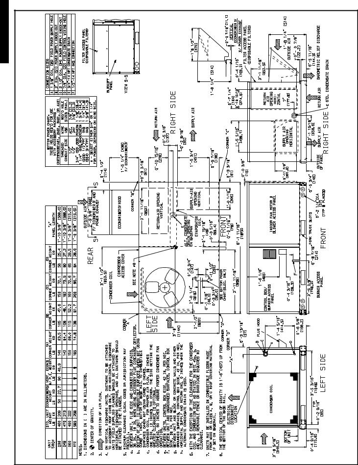
BASE UNIT DIMENSIONS — 580F036-072 |
580F036-151 |
a48-8195 |
26 |

BASE UNIT DIMENSIONS — 580F073
151-580F036 |
a48-8196 |
27 |
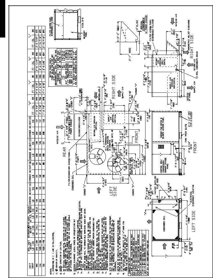
BASE UNIT DIMENSIONS — 580F090,120,150
580F036-151 |
a48-8197 |
28 |
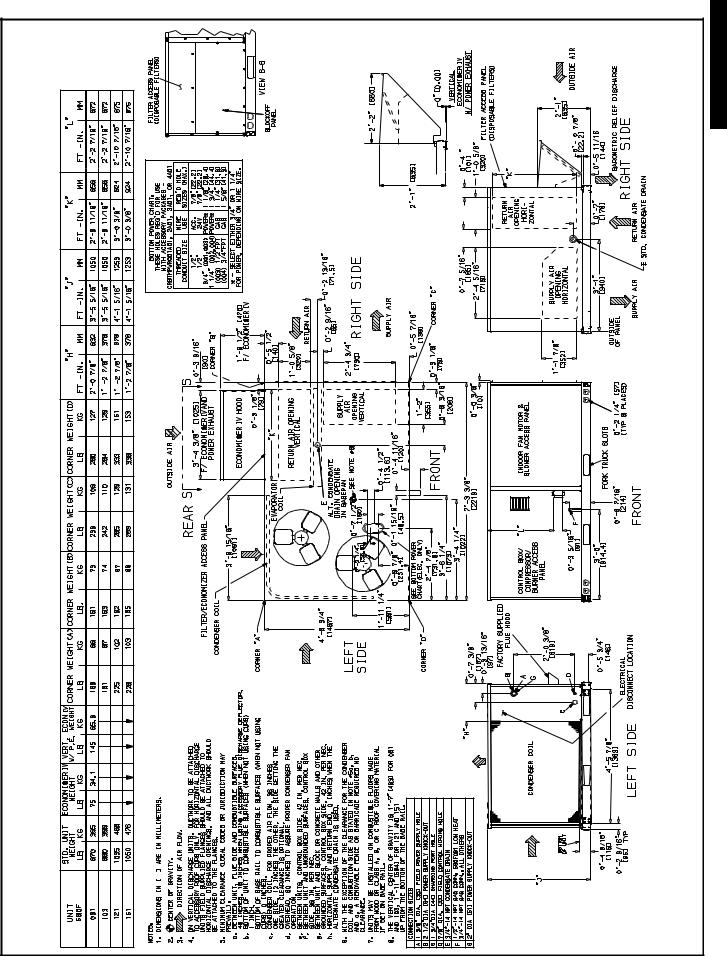
BASE UNIT DIMENSIONS — 580F091,103,121,151
151-580F036 |
a48-8198 |
29 |

ACCESSORY DIMENSIONS — 580F
151 |
ROOF CURB |
|
|
|
A |
|
|
UNIT SIZE |
|
|||||||||||||||||||||||||||||||
ACCESSORY |
|
|
|
|
|
|
||||||||||||||||||||||||||||||||||
580F036- |
CRRFCURB001A01 |
1′ -2″ |
|
|
|
|
|
|
580F |
|
||||||||||||||||||||||||||||||
|
|
|
|
|
|
|
|
|
|
|
|
|
|
[356] |
|
|
|
|
|
|
|
|||||||||||||||||||
|
CRRFCURB002A01 |
2′ -0″ |
036-073 |
|
|
|
|
|
|
|||||||||||||||||||||||||||||||
|
|
|
|
|
|
|
|
|
|
|
|
|
|
|
|
|
|
|
|
|||||||||||||||||||||
|
|
|
|
|
|
|
|
|
|
|
|
|
|
[610] |
|
|
|
|
|
|
|
|
|
|
|
|
|
|
|
|
|
|
|
|||||||
|
|
|
|
|
|
|
|
|
|
|
|
|
|
|
|
|
|
|
|
|
|
|
|
|
|
|
|
|
|
|
|
|
|
|
|
|
|
|
|
|
|
|
|
|
|
|
|
|
|
|
|
|
|
|
|
|
|
|
|
|
|
|
|
|
|
|
|
|
|
|
|
|
|
|
|
|
|
|
|
|
|
|
|
|
|
|
|
|
|
|
|
|
|
|
|
|
|
|
|
|
|
|
|
|
|
|
|
|
|
|
|
|
|
|
|
|
|
|
|
|
|
|
|
|
|
|
|
|
|
|
|
|
|
|
|
|
|
|
|
|
|
|
|
|
|
|
|
|
|
|
|
|
|
|
|
|
|
|
|
|
|
|
|
|
|
|
|
|
|
|
|
|
|
|
|
|
|
|
|
|
|
|
|
|
|
|
|
|
|
|
|
|
|
|
|
|
|
|
|
|
|
|
|
|
|
|
|
|
|
|
|
|
|
|
|
|
|
|
|
|
|
|
|
|
|
|
|
|
|
|
|
|
|
|
|
|
|
|
|
|
|
|
|
|
|
|
|
|
|
|
|
|
|
|
|
|
|
|
|
|
|
|
|
|
|
|
|
|
|
|
|
|
|
|
|
|
|
|
|
|
|
|
|
|
|
|
|
|
|
|
|
|
|
|
|
|
|
|
|
|
|
|
|
|
|
|
|
|
|
|
|
|
|
|
|
|
|
|
|
|
|
|
|
|
|
|
|
|
|
|
|
|
|
|
|
|
|
|
|
|
|
|
|
|
|
|
|
|
|
|
|
|
|
|
|
|
|
|
|
|
|
|
|
|
|
|
|
|
|
|
|
|
|
|
|
|
|
|
|
|
|
|
|
|
|
|
|
|
|
|
|
|
|
|
|
|
|
|
|
|
|
|
|
|
|
|
|
|
|
|
|
|
|
|
|
|
|
|
|
|
|
|
|
|
|
|
|
|
|
|
|
|
|
|
|
|
|
|
|
|
|
|
|
|
|
|
|
|
|
|
|
|
|
|
|
|
|
|
|
|
|
|
|
|
|
|
|
|
|
|
|
|
|
|
|
|
|
|
|
|
|
|
|
|
|
|
|
|
|
|
|
|
|
|
|
|
|
|
|
|
|
|
|
|
|
|
|
|
|
|
|
|
|
|
|
|
|
|
|
|
|
|
|
|
|
|
|
|
|
|
|
|
|
|
|
|
|
|
|
|
|
|
|
|
|
|
|
|
|
|
|
|
|
|
|
|
|
|
|
|
|
|
|
|
|
|
|
|
|
|
|
|
|
|
|
|
|
|
|
|
|
|
|
|
|
|
|
|
|
|
|
|
|
|
|
|
|
|
|
|
|
|
|
|
|
|
|
|
|
|
|
|
|
|
|
|
|
|
|
|
|
|
|
|
|
|
|
|
|
|
|
|
|
|
|
|
|
|
|
|
|
|
|
|
|
|
|
|
|
|
|
|
|
|
|
|
|
|
|
|
|
|
|
|
|
|
|
|
|
|
|
|
|
|
|
|
|
|
|
|
|
|
|
|
|
|
|
|
|
|
|
|
|
|
|
|
|
|
|
|
|
|
|
|
|
|
|
|
|
|
|
|
|
|
|
|
|
|
|
|
|
|
|
|
|
|
|
|
|
|
|
|
|
|
|
|
|
|
|
|
|
|
|
|
|
|
|
|
|
|
|
|
|
|
|
|
|
|
|
|
|
|
|
|
|
|
|
|
|
|
|
|
|
|
|
|
|
|
|
|
|
|
|
|
|
|
|
|
|
|
|
|
|
|
|
|
|
|
|
|
|
|
|
|
|
|
|
|
|
|
|
|
|
|
|
|
|
|
|
|
|
|
|
|
|
|
|
|
|
|
|
|
|
|
|
|
|
|
|
|
|
|
|
|
|
|
|
|
|
|
|
|
|
|
|
|
|
|
|
|
|
|
|
|
|
|
|
|
|
|
|
|
|
|
|
|
|
|
|
|
|
|
|
|
|
|
|
|
|
|
|
|
|
|
|
|
|
|
|
|
|
|
|
|
|
|
|
|
|
|
|
|
|
|
|
|
|
|
|
|
|
|
|
|
|
|
|
|
|
|
|
|
|
|
|
|
|
|
|
|
|
|
|
|
|
|
|
|
|
|
|
|
|
|
|
|
|
|
|
|
|
|
|
|
|
|
|
|
|
|
|
|
|
|
|
|
|
|
|
|
|
|
|
|
|
|
|
|
|
|
|
|
|
|
|
|
|
|
|
|
|
|
|
|
|
|
|
|
|
|
|
|
|
|
|
|
|
|
|
|
|
|
|
|
|
|
|
|
|
|
|
|
|
|
|
|
|
|
|
|
|
|
|
|
|
|
|
|
|
|
|
|
|
|
|
|
|
|
|
|
|
|
|
|
|
|
|
|
|
|
|
|
|
|
|
|
|
|
|
|
|
|
|
|
|
|
|
|
|
|
|
|
|
|
|
|
|
|
|
|
|
|
|
|
|
|
|
|
|
|
|
|
|
|
|
|
|
|
|
|
|
|
|
|
|
|
|
|
|
|
|
|
|
|
|
|
|
|
|
|
|
|
|
|
|
|
|
|
|
|
|
|
|
|
|
|
|
|
|
|
|
|
|
|
|
|
|
|
|
|
|
|
|
|
|
|
|
|
|
|
|
|
|
|
|
|
|
|
|
|
|
|
|
|
|
|
|
|
|
|
|
|
|
|
|
|
|
|
|
|
|
|
|
|
|
|
|
|
|
|
|
|
|
|
|
|
|
|
|
|
|
|
|
|
|
|
|
|
|
|
|
|
|
|
|
|
|
|
|
|
|
|
|
|
|
|
|
|
|
|
|
|
|
|
|
|
|
|
|
|
|
|
|
|
|
|
|
|
|
|
|
|
|
|
|
|
|
|
|
|
|
|
|
|
|
|
|
|
|
|
|
|
|
|
|
|
|
|
|
|
|
|
|
|
|
|
|
|
|
|
|
|
|
|
|
|
|
|
|
|
|
|
|
|
|
|
|
|
|
|
|
|
|
|
|
|
|
|
|
|
|
|
CONNECTOR |
|
|
|
D ALT |
|
|
|
|
ACCESSORY |
|||
B |
|
C |
DRAIN |
|
GAS |
POWER |
CONTROL |
|||||
PKG. ACCY. |
|
|
|
HOLE |
|
|
|
|
POWER |
|||
|
|
|
|
|
|
|
|
|
||||
CRBTMPWR001A01 |
|
|
|
|
|
|
3/4″ [19] NPT |
3/4″ [19] NPT |
1/2″ |
1/2″ |
||
CRBTMPWR002A01 |
11 |
/16″ |
1′ -4″ |
1 |
3 |
/4″ |
11/ ″ [31.7] |
|||||
|
1′ -9 |
|
|
|
4 |
[12.7] |
[12.7] |
|||||
CRBTMPWR003A01 |
[551] |
[406] |
[44.5] |
1/ |
″ [12.7] NPT |
3/ ″ [19] NPT |
||||||
NPT |
NPT |
|||||||||||
|
|
|
|
|
|
|
2 |
|
4 |
|||
CRBTMPWR004A01 |
|
|
|
|
|
|
3/4″ [19] NPT |
11/4″ [31.7] |
|
|
||
NOTES:
1.Roof curb accessory is shipped disassembled.
2.Insulated panels.
3. Dimensions in [ ] are in millimeters.
4.Roof curb, galvanized steel.
5.Attach ductwork to curb (flanges of duct rest on curb).
6.Service clearance: 4 ft on each side.
7. Direction of airflow.
8.Connector packages CRBTMPWR001A01 and 2A01 are for thru-the-curb type gas. Packages CRBTMPWR003A01 and 4A01 are for thru-the-bottom type gas connections.
a48-7317
Roof Curb
30
Loading...