


|
Bryant |
SINGLE PACKAGE |
Model 588A |
|
Air Conditioning |
||
|
|
GAS HEATING/ |
Sizes 018-060 |
|
|
ELECTRIC COOLING UNITS |
11¤2 to 5 Tons |
|
|
|
|
DESCRIPTION
All 588A models feature one piece, compact design and are fully self-contained units that are prewired, prepiped, and precharged for minimum installation expense. Unit is designed for easy use in either down¯ow (vertical) or horizontal applications.
STANDARD FEATURES
FACTORY-ASSEMBLED PACKAGE is a compact, fully selfcontained, gas heating/electric cooling unit that is prewired, prepiped, and precharged for minimum installation expense.
588A units are lightweight and available in a variety of standard heating and cooling sizes with voltage options to meet residential and light commercial requirements. Unit installs easily on a rooftop or a ground-level pad.
CONVERTIBLE DUCT CONFIGURATION on the 588A is designed for easy use in either down¯ow or horizontal discharge applications.
HIGH-EFFICIENCY DESIGN with SEERs (Seasonal Energy Ef- ®ciency Ratios) of 10.0.
DURABLE, DEPENDABLE COMPRESSORS are designed for high efficiency. Each compressor is hermetically sealed against contamination to help promote longer life and dependable operation. Each compressor also has vibration isolation to provide quiet operation. Rotary, reciprocating, or scroll compressors are used. Compressors have internal high-pressure and overcurrent protection.
DIRECT-DRIVE MULTISPEED, PSC (permanent split capacitor) BLOWER MOTOR is standard on all models.
DIRECT-DRIVE, PSC CONDENSER-FAN MOTORS are designed to help reduce energy consumption and provide for cooling operation down to 40 F.
REFRIGERANT SYSTEM is designed to provide dependability. Liquid refrigerant strainers are used to promote clean, unrestricted operation. Each unit leaves the factory with a full refrigerant charge. Refrigerant service connections make checking operating pressures easier.
EVAPORATOR AND CONDENSER COILS are computerdesigned for optimum heat transfer and cooling efficiency. Condenser coil is fabricated of copper tube and aluminum ®ns and is located inside the unit for protection against damage and for long life and reliable operation. The condenser coil is internally mounted and protected by a composite grille.
Copper ®n coils for condenser coil are also available by special order. These coils are recommended in applications where aluminum ®ns are likely to be damaged due to corrosion. Copper ®n coils are ideal for seacoast applications.
MONOPORT INSHOT BURNERS produce precise air-to-gas mixture, which provides for clean and efficient combustion. The large monoport on the inshot (or injection type) burners seldom, if ever, needs cleaning.
WEATHERIZED CABINETS are constructed of heavy-duty, phosphated, zinc-coated prepainted steel capable of withstanding 500 hours in salt spray. Interior surfaces of the evaporator compartment are insulated with foil-faced ®berglass to help keep the conditioned air from being affected by the outdoor ambient temperature and provide improved air quality. Conforms to American Society of Heating, Refrigeration and Air Conditioning Engineers (ASHRAE) No. 62P. Sloped condensate pan permits an external drain.
LOW SOUND RATINGS ensure a quiet indoor and outdoor environment with sound ratings as low as 7.4 bels.
EASY TO SERVICE CABINETS provide easy accessibility to serviceable components during maintenance and installation. Rounded corners are an important safety feature, and a highquality ®nish ensures an attractive appearance.
LOW AND HIGH VOLTAGE ELECTRICAL ENTRIES allow low and high voltage to be brought in either through the duct panel or rear ¯ue panel.
INTEGRATED GAS CONTROL BOARD provides safe and ef- ®cient control of heating and simpli®es troubleshooting through its built-in diagnostic function.
OPTIONAL BASE RAILS provide holes for rigging and handling as well as an elevated mounting frame that provides structural support for horizontal installations.
DOWNFLOW OPTIONS is converted for down¯ow at factory for easy vertical ductwork connections.
Form No. PDS 588A.18.4B
FACTORY-INSTALLED OPTIONS DESCRIPTION AND USAGE
Unit With Base Rail Ð Unit has rigging holes and an elevated mounting frame.
SUGGESTED USE:
·Rigging holes to provide greater ease in handling. Frame to provide elevation and structural support for horizontal applications.
Down¯ow Option Ð Unit is shipped from factory con®gured for down¯ow application. Unit is equipped with base rail.
SUGGESTED USE:
· To provide easy vertical ductwork connections.
FIELD-INSTALLED ACCESSORY DESCRIPTION AND USAGE
Flat Roof Curb Ð Consists of galvanized steel support frame in 8-, 11-, and 14-in. high designs. Provides wood nailer to attach roof counter ¯ashing. Insulated basepans in curbs are provided to prevent condensation. Ductwork attaches to rails provided in the roof curb. A gasket is provided to form an airtight and watertight seal between unit and curb. The roof curb design meets the standards of the NRCA (National Roo®ng Contractors' Association).
SUGGESTED USE:
·Slab-mounted applications when elevation of the unit above the slab is necessary.
·Rooftop application for down¯ow discharge.
·Curbs are preassembled and are available for ¯at or pitched roofs.
Pitched Roof Curb Ð Provided in ratios of 1, 2, 3, 4, 5, and 6 to 12 for use on pitched roof applications.
SUGGESTED USE:
· For when a roof curb is needed on a pitched roof.
Modulating Economizer Ð Economizer is available for down- ¯ow or horizontal applications, and is designed for easy installation. Economizer reduces energy costs and extends equipment life by allowing the use of outdoor air to supply ``free'' cooling when conditions are favorable.
Constant ventilation is recommended for light commercial applications when the conditioned space is occupied.
The economizer is shipped complete with a damper motor and linkage, enthalpy control, low-voltage wiring harness, and a rainhood. Adequate wire lengths are provided (additional ®eldsupplied wires are not required). Horizontal economizers are also furnished with a 2-in. disposable air ®lter and gasket material.
Modulating economizer package consists of low-leakage dampers with controls. The economizer will allow a ®xed percentage of outdoor ventilation air into the unit whenever the evaporator fan is running.
SUGGESTED USE:
·Allows outdoor air to be used for ``free'' cooling whenever the outdoor air is below the enthalpy control setting.
·To reduce energy usage. Use whenever the hours of operation at temperatures below 40 F are signi®cant.
Two-Position Damper Ð In the two-position dampers, the enthalpy control detects when outdoor air is suitable for ``free'' cooling by measuring the outdoor-air dry bulb temperature and humidity. Whenever the outdoor-air quality is acceptable for ``free'' cooling, the outdoor-air damper opens fully and the return-air damper closes, allowing outdoor air to enter the building.
SUGGESTED USE:
·Allows use of outdoor air to cool building without using compressor. Damper closes when evaporator fan is off to prevent cold backdraft, and wasted energy.
Manual Outdoor-Air Damper Ð Package consists of a manually adjustable damper and includes a rainhood and birdscreen.
SUGGESTED USE:
·To allow a ®xed percentage of outdoor air for ventilation under all conditions.
·The damper may be used on either down¯ow or horizontal air- ¯ow applications.
Thermostat and Subbase Ð These accessories provide cooling control for unit. Autochangeover and manual changeover types are available.
SUGGESTED USE:
·To operate and control unit, and to maintain desired building temperature.
The 0° F Low Ambient Kit Ð Kit permits operation down to 0° F.
SUGGESTED USE:
·When mechanical cooling is required when outdoor-air temperature is between 40 F and 0° F.
Natural-to-Propane Conversion Kit Ð Kit consists of gas ori- ®ces and other hardware required to convert the unit for use with LP (liquid propane) gas.
SUGGESTED USE:
·When natural gas cannot be obtained and liquid propane is used as fuel.
Filter Rack Ð Rack features easy installation and serviceability.
The ®lter rack housing is constructed of heavy-gage steel and is fully insulated. Both sides of the ®lter rack are ¯anged for easy installation.
SUGGESTED USE:
· Kit provides ability to locate ®lters inside the unit.
Flexible Duct Kit Ð Consists of 2 ¯exible UL-listed (Underwriters' Laboratories) ducts. The duct construction includes vapor barrier and 1-in. ®berglass insulation. The ``K'' factor is 0.23. Each duct has a square-to-round snap adapter for attachment to the accessory roof curb on one end, and a round clamp collar for attachment to the concentric diffuser box on the other end.
SUGGESTED USE:
·For use with accessory roof curb and concentric box to provide an easily-installed concentric system.
Concentric Diffuser Box Ð Is aerodynamically designed and equipped with a combination 4-way supply and a center return diffuser. A special core is provided within the diffuser box to provide even 4-way distribution.
SUGGESTED USE:
·For use with accessory roof curb and concentric box to provide an easily-installed concentric system.
Crankcase Heater Ð Warms crankcase oil to reduce refrigerant migration and ensure proper compressor lubrication.
SUGGESTED USE:
·For use in applications where crankcase is subjected to low outside temperatures. Recommended on 208/230-v, singlephase, 024-042 units only.
Solid-State ComprotecT Device Ð Package consists of a control to be ®eld-wired into the unit controls, and provides a 5-minute delay in compressor operation between cooling cycles.
SUGGESTED USE:
·Prevents compressor short cycling when rapid compressor cycles may be a problem.
2
FIELD-INSTALLED ACCESSORY DESCRIPTION AND
USAGE (cont)
Lifting Bracket Kit Ð Provides attachment point for rigging straps.
SUGGESTED USE:
·When unit needs to be lifted or moved. The kit is not required when unit is equipped with optional base rail or down¯ow application.
Highand Low-Pressure Switches Ð Protect the unit from running at unsuitable pressures.
SUGGESTED USE:
· Provides additional safety features when needed.
CONTENTS
Page
Model Description . . . . . . . . . . . . . . . . . . . . . . . . . . . . . . . . . 3
ARI Cooling Capacities . . . . . . . . . . . . . . . . . . . . . . . . . . . . . 4
Heating Capacities and Efficiencies . . . . . . . . . . . . . . . . . . . 4
Dimensional Drawings . . . . . . . . . . . . . . . . . . . . . . . . . . . . 5-10
Speci®cations. . . . . . . . . . . . . . . . . . . . . . . . . . . . . . . . . . 11,12
Selection Procedure . . . . . . . . . . . . . . . . . . . . . . . . . . . . . . 13
Net Cooling Capacities . . . . . . . . . . . . . . . . . . . . . . . . . . 14-16
Air Delivery . . . . . . . . . . . . . . . . . . . . . . . . . . . . . . . . . . . . 17,18
Electrical Data . . . . . . . . . . . . . . . . . . . . . . . . . . . . . . . . . . . 20
Operating Sequence . . . . . . . . . . . . . . . . . . . . . . . . . . . . . . 21
Typical Field Wiring . . . . . . . . . . . . . . . . . . . . . . . . . . . . . 22-24
Typical Installation . . . . . . . . . . . . . . . . . . . . . . . . . . . . . . . . 25
Application Data . . . . . . . . . . . . . . . . . . . . . . . . . . . . . . . . . 25
Engineers' Speci®cation Guide. . . . . . . . . . . . . . . . . . . . . . 26
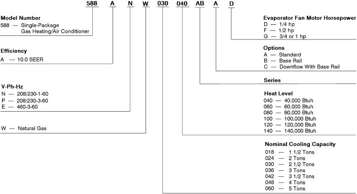
MODEL DESCRIPTION
3

ARI* COOLING CAPACITIES
UNIT 588A |
NOMINAL |
STANDARD |
NET COOLING² |
SEER²** |
SOUND RATINGS²² |
|
TONS |
CFM |
CAPACITIES (Btuh) |
(Bels) |
|||
|
|
|||||
018 |
11¤2 |
600 |
17,000 |
10.0 |
7.4 |
|
024 |
2 |
800 |
24,000 |
10.0 |
7.6 |
|
030 |
21¤2 |
1000 |
29,200 |
10.0 |
8.0 |
|
036 |
3 |
1200 |
36,000 |
10.0 |
8.0 |
|
042 |
31¤2 |
1400 |
42,500 |
10.0 |
8.2 |
|
048 |
4 |
1600 |
47,000 |
10.0 |
8.2 |
|
060 |
5 |
1995 |
59,500 |
10.0 |
8.2 |
|
|
|
|
|
|
|
|
|
LEGEND |
Bels |
Ð Sound Levels (1 bel = 10 decibels) |
|
db |
Ð dry bulb |
|
SEER |
Ð |
Seasonal Energy Efficiency Ratio |
wb |
Ð |
wet bulb |
*ARI Ð Air-conditioning and Refrigeration Institute.
²Rated in accordance with U.S. Government DOE (Department of Energy) test procedures and/or ARI (Air Conditioning and Refrigeration Institute) Standard 210/240-89.
**All units have factory-installed time-delay relay.
²²Rated in accordance with ARI Standard 270-84.
NOTE: Ratings are net values, re¯ecting the effects of circulating fan heat. Ratings are based on 80 F db, 67 F wb indoor entering-air temperature and 95 F db air entering outdoor unit.
OUTDOOR SOUND: ONE-THIRD OCTAVE BAND DATA Ð DECIBELS
MODEL NO. |
|
|
|
588A |
|
|
|
Frequency (Hz) |
018 |
024 |
030 |
036 |
042 |
048 |
060 |
63 |
49.8 |
38.1 |
45.7 |
47.8 |
45.5 |
56.0 |
54.3 |
125 |
56.5 |
55.0 |
58.1 |
59.3 |
61.2 |
65.6 |
65.1 |
250 |
60.3 |
65.3 |
68.7 |
67.4 |
70.4 |
71.5 |
71.5 |
500 |
59.8 |
67.2 |
64.7 |
68.8 |
69.9 |
71.4 |
72.7 |
1000 |
64.1 |
68.9 |
73.0 |
73.1 |
76.5 |
74.2 |
73.9 |
2000 |
64.1 |
65.5 |
70.2 |
69.5 |
71.3 |
73.3 |
73.4 |
4000 |
65.2 |
63.8 |
68.8 |
68.2 |
73.7 |
69.6 |
71.7 |
8000 |
56.0 |
60.3 |
66.6 |
65.8 |
65.5 |
67.1 |
66.3 |
HEATING CAPACITIES AND EFFICIENCIES
UNIT 588A |
|
HEATING INPUT |
OUTPUT CAPACITY |
TEMPERATURE |
AFUE (%) |
CSE (%) |
|
|
(Btuh) |
(Btuh) |
RISE RANGE (°F) |
||||
|
|
|
|
|
|||
|
018040 |
|
|
|
20-50 |
81.0 |
76.5 |
|
024040 |
|
40,000 |
32,800 |
20-50 |
81.0 |
76.5 |
|
030040 |
|
|
|
20-50 |
81.0 |
76.5 |
|
024060 |
|
|
|
25-55 |
81.0 |
77.5 |
|
030060 |
|
60,000 |
48,600 |
25-55 |
81.0 |
77.5 |
|
036060 |
|
25-55 |
81.0 |
77.5 |
||
|
|
|
|
||||
|
042060 |
|
|
|
25-55 |
81.0 |
77.5 |
|
030080 |
|
|
|
40-70 |
81.0 |
77.5 |
|
036080 |
|
|
|
40-70 |
81.0 |
77.5 |
|
042080 |
|
80,000 |
64,800 |
40-70 |
81.0 |
77.5 |
|
048080 |
|
|
|
40-70 |
81.0 |
77.5 |
|
060080 |
|
|
|
40-70 |
81.0 |
77.5 |
|
036100 |
|
|
|
50-80 |
81.0 |
78.0 |
|
042100 |
|
100,000 |
81,000 |
50-80 |
81.0 |
78.0 |
|
048100 |
|
50-80 |
81.0 |
78.0 |
||
|
|
|
|
||||
|
060100 |
|
|
|
50-80 |
81.0 |
78.0 |
|
036120 |
|
|
|
60-90 |
80.0 |
77.5 |
|
042120 |
|
120,000 |
97,200 |
60-90 |
80.0 |
77.5 |
|
048120 |
|
60-90 |
80.0 |
77.5 |
||
|
|
|
|
||||
|
060120 |
|
|
|
60-90 |
80.0 |
77.5 |
|
048140 |
|
140,000 |
113,000 |
50-80 |
80.0 |
77.5 |
|
060140 |
|
50-80 |
80.0 |
77.5 |
||
|
|
|
|
||||
|
|
LEGEND |
|
|
|
|
|
AFUE |
Ð Annual Fuel Utilization Efficiency |
|
|
|
|
||
CSE |
Ð California Seasonal Efficiency |
|
|
|
|
||
NOTE: Before purchasing this appliance, read important energy cost and efficiency information available from your retailer.
4
CG COND LV
NOTE: outdoor
REQ'D
Duct
Unit
Side
(Except
REQ'D
Unit
Duct
Side
Bottom
Flue
NEC
Between
Unit
Unit
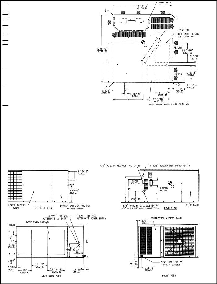
DIMENSIONAL DRAWINGS
Unit 588A Sizes 018-042 Without Base Rail
5
588A018040
588A024040
588A024060
588A030040
CG
COND
LV
NOTE: outdoor
REQ'D
Duct Unit top Side
Compressor (Except
REQ'D
Maximum
Unit top
Duct side
Side
Bottom
Flue
NEC
Between
Unit and
Unit and
grounded
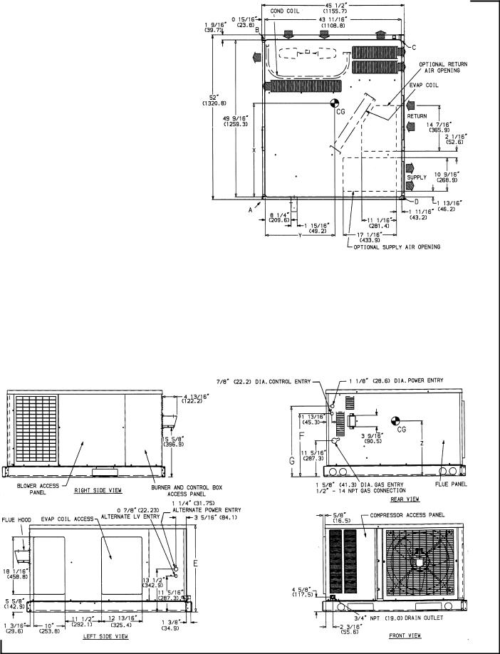
DIMENSIONAL DRAWINGS (cont)
Unit 588A Sizes 018-060 With Optional Base Rail
6
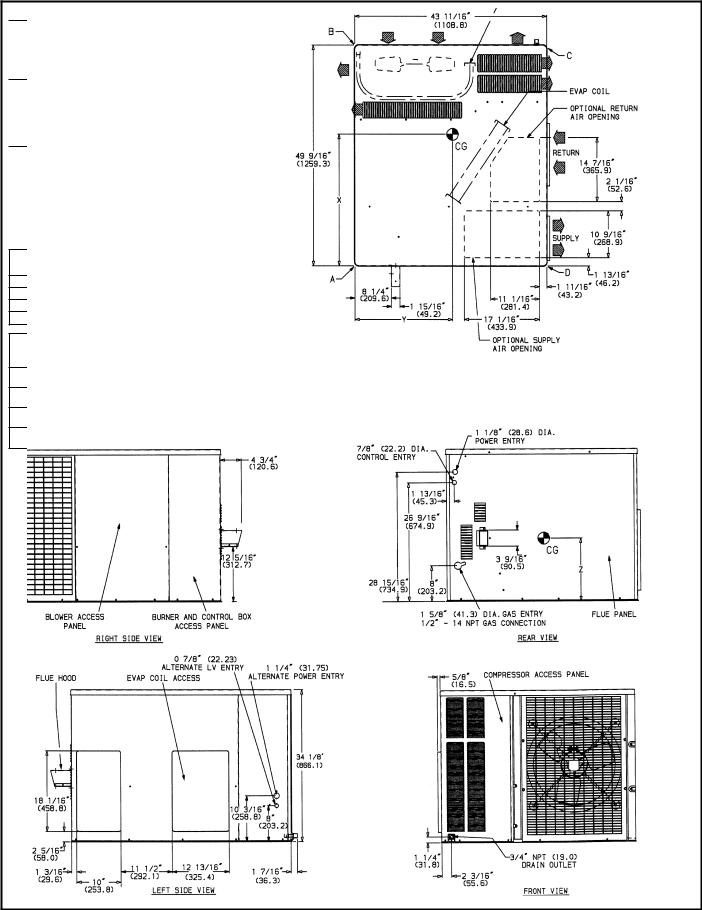
DIMENSIONAL DRAWINGS (cont)
REQ'D
Duct
Unit
Side
(Except
REQ'D
Maximum
Unit
Duct
Side
Bottom
Flue
NEC
Between Unit Unit
surfaces,
CG
COND
LV
NOTE: outdoor
Unit 588A, Sizes 048,060 Without Base Rail
7

DIMENSIONAL DRAWINGS (cont)
REQ'D CLEARANCES FOR SERVICING. in. (mm)
Duct
Unit
Side
(Except
REQ'D
Unit
Duct
Side
Bottom
Flue
NEC
Between Unit Unit
surfaces,
CG
COND
LV
NOTE: outdoor
Unit 588A Sizes 048,060 With Optional Base Rail
8
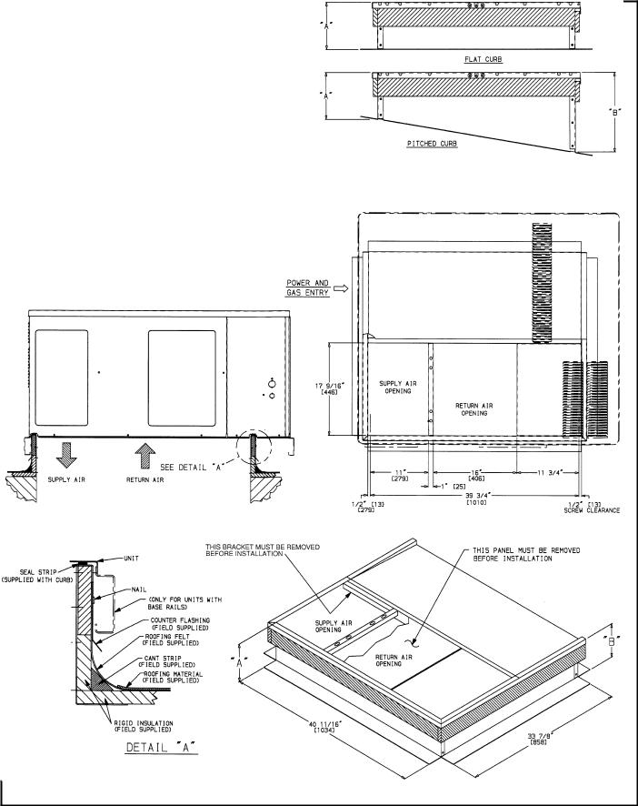
DIMENSIONAL DRAWINGS (cont)
|
PART NUMBER |
``A'' |
``B'' |
PITCH |
|||
|
389099-701 |
89 |
[203] |
Ð |
Ð |
||
FLAT |
389100-701 |
119 [279] |
Ð |
Ð |
|||
|
389101-701 |
149 |
[356] |
Ð |
Ð |
||
|
389103-701 |
89 |
[203] |
107¤89 [276] |
1:12 |
||
|
389104-701 |
89 |
[203] |
139¤169 [344] |
2:12 |
||
PITCHED |
389105-701 |
89 |
[203] |
163¤89 |
[416] |
3:12 |
|
389106-701 |
89 |
[203] |
191¤49 |
[489] |
4:12 |
||
|
|||||||
|
389107-701 |
89 |
[203] |
223¤89 |
[568] |
5:12 |
|
|
389108-701 |
89 |
[203] |
255¤89 |
[651] |
6:12 |
|
NOTES:
1.Roof curb must be set up for unit being installed.
2.Seal strip must be applied as required for unit being installed.
3. Dimensions in [ ] are in millimeters.
4.Roof curb is made of 16 gage steel.
5.Attach ductwork to curb (¯anges of duct rest on curb).
6.Service clearance 4 ft on each side.
7. Direction of air¯ow.
8.Insulated panels: 1-in. thick ®berglass, 1 lb density.
Roof Curb, Sizes 018-060
9
 Loading...