


 Loading...
113A
Legacy-RNC Line 13 Air Conditioner with Puronr Refrigerant
1-1/2 to 5 Nominal Tons (Sizes 018-060)
Product Data
the environmentally sound refrigerant
Bryant’s Air Conditioners with Puron r refrigerant provide a collection of features unmatched by any other family of equipment. The 113A has been designed utilizing Bryant’s Puron refrigerant. The environmentally sound refrigerant allows you to make a responsible decision in the protection of the earth’s ozone layer.
As an Energy Star r Partner, Bryant Heating and Cooling has determined that this product meets the Energy Starr guidelines for energy efficiency. Refer to the combination ratings in the Product Data for system combinations that meet Energy Starr guidelines.
NOTE: Ratings contained in this document are subject to change at any time. Always refer to the AHRI directory (www.ahridirectory.org) for the most up-to-date ratings information.
INDUSTRY LEADING
FEATURES / BENEFITS
Efficiency
S 13 - 14.5 SEER/10.55 - 12 EER
S Microtube Technologyt refrigeration system S Indoor air quality accessories available
Sound
S Sound level as low as 76 dBA
S Sound level as low as 74 dBA with accessory sound blanket
Comfort
S System supports Thermidistatt or standard thermostat controls
Reliability
SPuronr refrigerant - environmentally sound, won’t deplete the ozone layer and low lifetime service cost.
S Scroll compressor
S Internal pressure relief valve S Internal thermal overload
S Filter drier
S Balanced refrigeration system for maximum reliability
Durability
DuraGuardt protection package:
S Solid, durable sheet metal construction S Dense wire coil guard
S Baked-on, complete outer coverage, powder paint
Applications
SLong-line - up to 250 feet (76.20 m) total equivalent length, up to 200 feet (60.96 m) condenser above evaporator, or up to 80 ft. (24.38 m) evaporator above condenser (See Longline Guide for
more information.)
S Low ambient (down to -20_F/-28.9_C) with accessory kit
Warranty
S 5 year limited compressor warranty S 5 year limited parts warranty

113A
MODEL NUMBER NOMENCLATURE
1 |
2 |
3 |
4 |
5 |
6 |
|
7 |
8 |
9 |
10 |
11 |
12 |
14 |
N |
N |
N |
A |
A/N |
N |
N |
N |
N |
A/N |
A/N |
N |
A |
|
1 |
1 |
3 |
A |
N |
A |
0 |
3 |
6 |
0 |
0 |
0 |
0 |
|
Product |
Tier |
SEER |
Major |
Voltage |
Variations |
Cooling Capacity |
Open |
Open |
Open |
Series |
|||
Family |
Series |
|
|
|
|||||||||
|
|
|
|
|
|
|
|
|
|
|
|
||
|
1= |
|
|
N= 208---230---1 |
|
|
|
|
|
0=Not |
0=Not |
0=Not |
|
1=AC |
Legacy |
3=13 SEER |
A=Puron |
A = Standard |
|
|
|
Defined |
|
||||
|
RNC |
|
|
or 208/230---1 |
|
|
|
|
|
Defined |
Defined |
|
|
|
|
|
|
|
|
|
|
|
|
|
|
|
|
|
|
|
|
|
ISO 9001:2000 |
|
|
|
|
|
|
|
|
|
|
|
|
|
|
|
|
|
|
|
|||
|
|
|
|
|
|
|
|
|
|
|
|
||
the environmentally sound refrigerant |
|
|
REGISTERED |
|
|
|
|
|
|
|
|||
This product has been designed and manufactured to meet Energy Star→ criteria for energy efficiency when matched with appropriate coil components.
However, proper refrigerant charge and proper air flow are critical to achieve rated capacity and efficiency. Installation of this product should follow all manufacturing refrigerant charging and air flow instructions. Failure to confirm proper charge and air flow may reduce energy efficiency and shorten equipment life.
STANDARD FEATURES
Feature |
018 |
024 |
030 |
036 |
042 |
048 |
060 |
|
|
|
|
|
|
|
|
Puron Refrigerant |
X |
X |
X |
X |
X |
X |
X |
|
|
|
|
|
|
|
|
Maximum SEER |
14.5 |
14.5 |
14.5 |
14.0 |
14.0 |
14.5 |
13.5 |
|
|
|
|
|
|
|
|
Scroll Compressor |
X |
X |
X |
X |
X |
X |
X |
|
|
|
|
|
|
|
|
Dense Wire Coil Guard |
X |
X |
X |
X |
X |
X |
X |
|
|
|
|
|
|
|
|
Field Installed Filter Drier |
X |
X |
X |
X |
X |
X |
X |
|
|
|
|
|
|
|
|
Front Seating Service Valves |
X |
X |
X |
X |
X |
X |
X |
|
|
|
|
|
|
|
|
Internal Pressure Relief Valve |
X |
X |
X |
X |
X |
X |
X |
|
|
|
|
|
|
|
|
Internal Thermal Overload |
X |
X |
X |
X |
X |
X |
X |
|
|
|
|
|
|
|
|
Long Line capability |
X |
X |
X |
X |
X |
X |
X |
|
|
|
|
|
|
|
|
Low Ambient capability with Kit |
X |
X |
X |
X |
X |
X |
X |
|
|
|
|
|
|
|
|
X = Standard |
|
|
|
|
|
|
|
2

PHYSICAL DATA
UNIT SIZE---VOLTAGE, SERIES |
018---D |
024---D |
030---E |
|
036---E |
|
042---C |
048---E |
060---F |
|
|
|
|
|
|
|
|
|
|
Operating Weight lb (kg) |
107 |
110 |
111 |
|
141 |
|
190 |
186 |
190 |
(48.5) |
(49.9) |
(50.3) |
|
(64.0) |
|
(86.2) |
(84.4) |
(86.2) |
|
|
|
|
|||||||
Shipping Weight lb (kg) |
130 |
134 |
136 |
|
170 |
|
218 |
224 |
226 |
(59.0) |
(60.8) |
(61.7) |
|
(77.1) |
|
(98.9) |
(101.6) |
(102.5) |
|
|
|
|
|||||||
Compressor Type |
|
|
|
|
Scroll |
|
|
|
|
REFRIGERANT |
|
|
|
Puron→ (R---410A) |
|
|
|
||
Control |
|
|
TXV (Puron→ Hard Shutoff) |
|
|
||||
Charge lb (kg) |
3.50 |
3.80 |
4.1 |
|
5.34 |
|
5.84 |
7.00 |
8.19 |
(1.60) |
(1.72) |
(1.86) |
|
(2.42) |
|
(2.65) |
(3.18) |
(3.71) |
|
|
|
|
|||||||
COND FAN |
|
|
Propeller |
Type, Direct |
Drive |
|
|
||
Air Discharge |
|
|
|
|
Vertical |
|
|
|
|
Air Qty (CFM) |
1792 |
2218 |
2218 |
|
2954 |
|
3167 |
3644 |
3129 |
Motor HP |
1/12 |
1/10 |
1/10 |
|
1/4 |
|
1/5 |
1/4 |
1/4 |
Motor RPM |
1100 |
1100 |
1100 |
|
1100 |
|
1100 |
1100 |
800 |
COND COIL |
|
|
|
|
|
|
|
|
|
Face Area (Sq ft) |
8.4 |
8.4 |
9.80 |
|
13.13 |
|
17.25 |
19.40 |
12.93 |
Fins per In. |
20 |
25 |
25 |
|
25 |
|
25 |
25 |
20 |
Rows |
1 |
1 |
1 |
|
1 |
|
1 |
1 |
2 |
Circuits |
3 |
3 |
3 |
|
3 |
|
4 |
5 |
5 |
VALVE CONNECT. (In. ID) |
|
|
|
|
|
|
|
|
|
Vapor |
3/4 |
3/4 |
3/4 |
|
7/8 |
|
7/8 |
7/8 |
1---1/8 |
Liquid |
|
|
|
|
3/8 |
|
|
|
|
REFRIGERANT TUBES (In. OD) |
|
|
|
|
|
|
|
|
|
Rated Vapor* |
3/4 |
3/4 |
7/8 |
|
7/8 |
|
1---1/8 |
1---1/8 |
1---1/8 |
Liquid |
|
|
|
|
3/8 |
|
|
|
|
* Units are rated with 25 ft (7.6 m) of lineset length. See Vapor Line Sizing and Cooling Capacity Loss table when using other sizes and lengths of lineset. Note: See unit Installation Instruction for proper installation.
113A
VAPOR LINE SIZING AND COOLING CAPACITY LOSS
LONG LINE APPLICATION: An application is considered ”Long line” when the total equivalent tubing length exceeds 80 ft. (24.38 m) or when there is more than 20 ft. (6.09 m) vertical separation between indoor and outdoor units. These applications require additional accessories and system modifications for reliable system operation. The maximum allowable total equivalent length is up to 250 ft. (76.2 m). The maximum vertical separation 200 ft. (60.96
m) when outdoor unit is above indoor unit, and up to 80 ft. (24.38 m) when the outdoor unit is below the indoor unit. Refer to Accessory Usage Guideline below for required accessories. See Longline Application Guideline for required piping and system modifications. Also, refer to the table below for the vapor tube diameters based on the total length to minimize the cooling capacity loss.
|
|
|
|
|
|
|
|
|
Cooling Capacity Loss (%) |
|
|
|
|
||
|
Unit |
|
Maximum |
Vapor Line |
|
|
|
Total Equivalent Line Length ft. (m) |
|
|
|
|
|||
|
|
Liquid Line |
Standard |
|
|
|
|
|
|
|
|
|
|||
|
Nominal |
|
Diameters |
|
|
Long Line Application Requires Accessories |
|
||||||||
|
|
Diameters |
Application |
|
|
|
|||||||||
|
Size (Btuh) |
|
(In. OD) |
|
|
|
|
|
|
|
|
|
|||
|
|
(In. OD) |
|
|
|
|
|
|
|
|
|
|
|
||
|
|
|
|
26---50 |
51---80 |
81---100 |
|
101---125 |
126---150 |
151---175 |
176---200 |
|
201---225 |
226---250 |
|
|
|
|
|
|
|
|
|||||||||
|
|
|
|
|
(7.9---15.2) |
(15.5---24.4) |
(24.7---30.5) |
|
(30.8---38.1) |
(38.4---45.7) |
(46.0---53.3) |
(53.6---61.0) |
|
(61.3---68.6) |
(68.9---76.2) |
|
18000 |
|
3/8 |
1/2 |
1 |
2 |
3 |
|
5 |
6 |
7 |
8 |
|
9 |
11 |
|
1 Stage |
|
5/8 |
0 |
1 |
1 |
|
1 |
2 |
2 |
2 |
|
3 |
3 |
|
|
Puron AC |
|
|
3/4 |
0 |
0 |
0 |
|
0 |
1 |
1 |
1 |
|
1 |
1 |
|
24000 |
|
3/8 |
5/8 |
0 |
1 |
2 |
|
2 |
3 |
3 |
4 |
|
5 |
5 |
|
1 Stage |
|
3/4 |
0 |
0 |
1 |
|
1 |
1 |
1 |
1 |
|
2 |
2 |
|
|
Puron AC |
|
|
7/8 |
0 |
0 |
0 |
|
0 |
0 |
1 |
1 |
|
1 |
1 |
|
30000 |
|
3/8 |
5/8 |
1 |
2 |
3 |
|
3 |
4 |
5 |
6 |
|
7 |
8 |
|
1 Stage |
|
3/4 |
0 |
0 |
1 |
|
1 |
1 |
2 |
2 |
|
2 |
3 |
|
|
Puron AC |
|
|
7/8 |
0 |
0 |
0 |
|
0 |
1 |
1 |
1 |
|
1 |
1 |
|
36000 |
|
3/8 |
5/8 |
1 |
2 |
4 |
|
5 |
6 |
8 |
9 |
|
10 |
12 |
|
1 Stage |
|
3/4 |
0 |
1 |
1 |
|
2 |
2 |
3 |
3 |
|
4 |
4 |
|
|
Puron AC |
|
|
|
|
|
|
|
|
|
|
|
|
|
|
|
|
|
7/8 |
0 |
0 |
0 |
|
1 |
1 |
1 |
1 |
|
2 |
2 |
|
|
42000 |
|
3/8 |
3/4 |
0 |
1 |
2 |
|
2 |
3 |
4 |
4 |
|
5 |
6 |
|
1 Stage |
|
7/8 |
0 |
0 |
1 |
|
1 |
1 |
2 |
2 |
|
2 |
3 |
|
|
Puron AC |
|
|
1 1/8 |
0 |
0 |
0 |
|
0 |
0 |
0 |
0 |
|
0 |
0 |
|
48000 |
|
3/8 |
3/4 |
0 |
1 |
2 |
|
3 |
4 |
5 |
5 |
|
6 |
7 |
|
1 Stage |
|
7/8 |
0 |
0 |
1 |
|
1 |
2 |
2 |
2 |
|
3 |
3 |
|
|
Puron AC |
|
|
|
|
|
|
|
|
|
|
|
|
|
|
|
|
|
1 1/8 |
0 |
0 |
0 |
|
0 |
0 |
0 |
0 |
|
1 |
1 |
|
|
60000 |
|
3/8 |
3/4 |
1 |
2 |
4 |
|
5 |
6 |
7 |
9 |
|
10 |
11 |
|
1 Stage |
|
7/8 |
0 |
1 |
2 |
|
2 |
3 |
4 |
4 |
|
5 |
5 |
|
|
Puron AC |
|
|
1 1/8 |
0 |
0 |
0 |
|
1 |
1 |
1 |
1 |
|
1 |
1 |
|
|
|
|
|
|||||||||||
|
Applications in this area are long line. Accessories are required as shown recommended on Long Line Application Guidelines |
|
|
|
|||||||||||
|
Applications in this area may have height restrictions that limit allowable total equivalent length, when outdoor unit is below indoor unit |
See Long Line Applica- |
|||||||||||||
|
tion Guidelines |
|
|
|
|
|
|
|
|
|
|
|
|
|
|
|
|
|
|
|
|
|
|
|
|
|
|
|
|
|
|
3

ACCESSORY THERMOSTATS
THERMOSTAT / SUBBASE PKG. |
DESCRIPTION |
|
T6 |
---PRH---01 |
Programmable Thermidistat |
|
|
|
T6 |
---NRH---01 |
Non---programmable Thermidistat |
|
|
|
T1 |
---PAC---01 |
Legacy RNC Series Programmable AC Stat |
|
|
|
T1 |
---NAC---01 |
Legacy RNC Series Non---programmable AC Stat |
|
|
|
TSTATBBPRH01---B |
Thermidistat Control --- Programmable / Non---Programmable Thermostat with Humidity control |
|
|
|
|
TSTATBBPAC01---B |
Thermostat --- Auto Changeover, 7---Day Programmable, _F/_C, 1---Stage Heat, 1---Stage Cool |
|
|
|
|
TSTATBBNAC01---C |
Thermostat --- Auto Changeover, Non---Programmable, _F/_C, 1---Stage Heat, 1---Stage Cool |
|
|
|
|
TSTATBBBAC01---B |
Builder’s Thermostat --- Manual Changeover, Non---Programmable, _F/_C, 1---Stage Heat, 1---Stage Cool |
|
|
|
|
TSTATBBSEN01---B |
Outdoor Air Temperature Sensor |
|
|
|
|
TSTATXXBBP01 |
Backplate for Builder’s Thermostat |
|
|
|
|
TSTATXXNBP01 |
Backplate for Non---Programmable Thermostat |
|
|
|
|
TSTATXXPBP01 |
Backplate for Programmable Thermostat |
|
|
|
|
TSTATXXCNV10 |
Thermostat Conversion Kit (4 to 5 wires) --- 10 Pack |
|
|
|
ACCESSORIES |
|
|
|
|
|
|
|
|
113A |
|
|
|
|
|
|
|
|
|
|
KIT NUMBER |
DESCRIPTION |
|
|
Size --- Voltage & Series |
|
|
||||
|
|
|
|
|
|
|
||||
|
|
018---D |
024---D |
030---E |
036---E |
042---C |
048---E |
060---F |
||
|
|
|
|
|
|
|
|
|
||
|
|
KAAFT0101AAA |
FREEZE THERMOSTAT |
X |
X |
X |
X |
X |
X |
X |
|
|
|
|
|
|
|
|
|
|
|
|
|
KAATD0101TDR |
TIME DELAY RELAY |
X |
X |
X |
X |
X |
X |
X |
|
|
|
|
|
|
|
|
|
|
|
|
|
KAAWS0101AAA |
WINTER START |
X |
X |
X |
X |
X |
X |
X |
|
|
|||||||||
|
|
|
|
|
|
|
|
|
|
|
|
|
KSALA0301410 |
LOW AMBIENT PSW |
X |
X |
X |
X |
X |
X |
X |
|
|
|
|
|
|
|
|
|
|
|
|
|
KSALA0601AAA{ |
MOTORMASTER 230V |
X |
X |
X |
X |
X |
X |
X |
|
|
|
|
|
|
|
|
|
|
|
|
|
HC32GE234 |
MOTOR FAN BALL BEARING |
X |
|
|
|
|
|
|
|
|
|
|
|
|
|
|
|
|
|
|
|
HC34GE239 |
MOTOR FAN BALL BEARING |
|
X |
X |
|
|
|
|
|
|
|
|
|
|
|
|
|
|
|
|
|
HC40GE226 |
MOTOR FAN BALL BEARING |
|
|
|
X |
|
X |
|
|
|
|
|
|
|
|
|
|
|
|
|
|
HC38GE219 |
MOTOR FAN BALL BEARING |
|
|
|
|
X |
|
|
|
|
|
|
|
|
|
|
|
|
|
|
|
HC40GE228 |
MOTOR FAN BALL BEARING |
|
|
|
|
|
|
X |
|
|
|
|
|
|
|
|
|
|
|
|
|
KSAHS1701AAA |
HARD START (CAP / RELAY) |
X |
X |
X |
X |
X |
X |
X |
|
|
|
|
|
|
|
|
|
|
|
|
|
KSACY0101AAA |
CYCLE PROTECTOR |
X |
X |
X |
X |
X |
X |
X |
|
|
|
|
|
|
|
|
|
|
|
|
|
KSASF0101AAA |
SUPPORT FEET |
X |
X |
X |
X |
X |
X |
X |
|
|
|
|
|
|
|
|
|
|
|
|
|
KAACS0201PTC |
START ASSIST PTC |
X |
X |
X |
X |
X |
X |
X |
|
|
|
|
|
|
|
|
|
|
|
|
|
KAACH1401AAA |
CRANKCASE HTR |
X |
X |
X |
X |
|
|
|
|
|
|
|
|
|
|
|
|
|
|
|
|
KAACH1201AAA |
CRANKCASE HTR |
|
|
|
|
X |
X |
X |
|
|
|
|
|
|
|
|
|
|
|
|
|
KSATX0201PUR |
TXV PURON HSO |
X |
X |
X |
|
|
|
|
|
|
|
|
|
|
|
|
|
|
|
|
|
KSATX0301PUR |
TXV PURON HSO |
|
|
|
X |
X |
|
|
|
|
|
|
|
|
|
|
|
|
|
|
|
KSATX0401PUR |
TXV PURON HSO |
|
|
|
|
|
X |
|
|
|
|
|
|
|
|
|
|
|
|
|
|
KSATX0501PUR |
TXV PURON HSO |
|
|
|
|
|
|
X |
|
|
|
|
|
|
|
|
|
|
|
|
|
KSASH0601COP |
SOUND HOOD |
X |
X |
X |
X |
X |
X |
|
|
|
|
|
|
|
|
|
|
|
|
|
|
KSASH2101COP |
SOUND HOOD |
|
|
|
|
|
|
X |
|
|
|
|
|
|
|
|
|
|
|
|
|
KAALP0401PUR |
LOW PRESSURE SWITCH |
X |
X |
X |
X |
X |
X |
X |
|
|
|
|
|
|
|
|
|
|
|
|
|
KAAHI0501PUR |
HIGH PRESSURE SWITCH |
X |
X |
X |
X |
X |
X |
X |
|
|
|
|
|
|
|
|
|
|
|
X = Available accessories
{Required accessories include ball bearing fan motor, compressor start assist (CAP / Relay), crankcase heater, evaporator freeze stat, hard shut---off TXV.
4

ACCESSORY USAGE GUIDELINE
|
REQUIRED FOR LOW---AMBI- |
REQUIRED FOR LONG |
REQUIRED FOR |
|
|
LINE |
SEA COAST |
||
ACCESSORY |
ENT COOLING APPLICATIONS |
|||
APPLICATIONS* |
APPLICATIONS |
|||
|
(Below 55°F/12.8_C) |
|||
|
(Over 80 ft./24.38 m) |
(Within 2 miles/3.22 km) |
||
|
|
|||
Ball Bearing Fan Motor |
Yes{ |
No |
No |
|
|
|
|
|
|
Compressor Start Assist Capacitor and Relay |
Yes |
Yes |
No |
|
Crankcase Heater |
Yes |
Yes |
No |
|
|
|
|
|
|
Evaporator Freeze Thermostat |
Yes |
No |
No |
|
|
|
|
|
|
Hard Shut---Off TXV |
Yes |
Yes |
Yes |
|
Liquid Line Solenoid Valve |
No |
No |
No |
|
|
|
|
|
|
Motor Master→ Control or |
Yes |
No |
No |
|
Low---ambient Pressure Switch |
||||
|
|
|
||
|
|
|
|
|
Support Feet |
Recommended |
No |
Recommended |
|
Winter Start Control |
Yes |
No |
No |
*For tubing line sets between 80 and 200 ft. (24.38 and 60.96 m) and/or 20 ft. (6.09 m) vertical differential, refer to Residential Split---System Longline Application Guideline.
{ Required for Low---Ambient Controller (full modulation feature) MotorMasterr Control.
Accessory Description and Usage (Listed Alphabetically)
1. Ball-Bearing Fan Motor
A fan motor with ball bearings which permits speed reduction while maintaining bearing lubrication.
Usage Guideline:
Required on all units when MotorMasterr is used.
2. Compressor Start Assist - Capacitor and Relay
Start capacitor and relay gives a ”hard” boost to compressor motor at each start up.
Usage Guideline:
Required for reciprocating compressors in the following applications:
Long line
Low ambient cooling
Hard shut off expansion valve on indoor coil Liquid line solenoid on indoor coil
Required for single-phase scroll compressors in the following applications:
Long line
Low ambient cooling
Suggested for all compressors in areas with a history of low voltage problems.
3. Compressor Start Assist — PTC Type
Solid state electrical device which gives a ”soft” boost to the compressor at each start-up.
Usage Guideline:
Suggested in installations with marginal power supply.
4. Crankcase Heater
An electric resistance heater which mounts to the base of the compressor to keep the lubricant warm during off cycles. Improves compressor lubrication on restart and minimizes the chance of liquid slugging.
Usage Guideline:
Required in low ambient cooling applications. Required in long line applications.
Suggested in all commercial applications.
5. Cycle Protector
The cycle protector is designed to prevent compressor short cycling. This control provides an approximate 5-minute delay after power to the compressor has been interrupted for any reason, including power outage, protector control trip, thermostat jiggling, or normal cycling.
6. Evaporator Freeze Thermostat
An SPST temperature-actuated switch that stops unit operation when evaporator reaches freeze-up conditions.
Usage Guideline:
Required when low ambient kit has been added.
7. Low-Ambient Pressure Switch Kit
A long life pressure switch which is mounted to outdoor unit service valve. It is designed to cycle the outdoor fan motor in order to maintain head pressure within normal operating limits (approximately 100 psig to 225 psig). The control will maintain working head pressure at low-ambient temperatures down to 0_F (-18_C) when properly installed.
Usage Guideline:
A Low-Ambient Pressure Switch or MotorMasterr Low-Ambient Controller must be used when cooling operation is used at outdoor temperatures below 55_F (12.8_C).
8. MotorMasterr Low-Ambient Controller
A fan-speed control device activated by a temperature sensor, designed to control condenser fan motor speed in response to the saturated, condensing temperature during operation in cooling mode only. For outdoor temperatures down to -20_F (-28.9_C), it maintains condensing temperature at 100_F ±10_F (37.8_C ± 5.5_C).
Usage Guideline:
A MotorMasterr Low Ambient Controller or Low-Ambient Pressure Switch must be used when cooling operation is used at outdoor temperatures below 55_F (12.8_C).
Suggested for all commercial applications.
9. Outdoor Air Temperature Sensor
Designed for use with Bryant Thermostats listed in this publication. This device enables the thermostat to display the outdoor temperature. This device also
is required to enable special thermostat features such as auxiliary heat lock out.
Usage Guideline:
Suggested for all Bryant thermostats listed in this publication.
113A
5

113A
Accessory Description and Usage (Listed Alphabetically) (Continued)
10. Sound Hood
Wraparound sound reducing cover for the compressor. Reduces the sound level by about 2 dBA.
Usage Guideline:
Suggested when unit is installed closer than 15 ft (4.57 m) to quiet areas, bedrooms, etc.
Suggested when unit is installed between two houses less than 10 ft (3.05 m) apart.
11. Support Feet
Four stick-on plastic feet that raise the unit 4 in. (101.6 mm) above the mounting pad. This allows sand, dirt, and other debris to be flushed from the unit base, minimizing corrosion.
Usage Guideline:
Suggested in the following applications: Coastal installations.
Windy areas or where debris is normally circulating. Rooftop installations.
For improved sound ratings.
12. Thermostatic Expansion Valve (TXV)
A modulating flow-control valve which meters refrigerant liquid flow rate into the evaporator in response to the superheat of the refrigerant gas leaving the evaporator.
Kit includes valve, adapter tubes, and external equalizer tube. Hard shut off types are available.
NOTE: When using a hard shut off TXV with single phase reciprocating compressors, a Compressor Start Assist Capacitor and Relay is required.
13. Time-Delay Relay
An SPST delay relay which briefly continues operation of indoor blower motor to provide additional cooling after the compressor cycles off.
NOTE: Most indoor unit controls include this feature. For those that do not, use the guideline below.
Usage Guideline:
For improved efficiency ratings for certain combinations of indoor and outdoor units. Refer to ARI Unitary Directory.
14. Winter Start Control
This control is designed to alleviate nuisance opening of the low-pressure switch by bypassing it for the first 3 minutes of operation.
Usage Guideline:
Required to achieve ARI ratings in certain equipment combinations. Refer to combination ratings.
Hard shut off TXV or LLS required in air conditioner long line applications.
Required for use on all zoning systems.
6

ELECTRICAL DATA
UNIT |
|
|
|
|
|
|
|
MIN WIRE |
MIN WIRE |
MAX |
MAX |
MAX |
|
OPER VOLTS* |
COMPR |
FAN |
|
LENGTH |
LENGTH |
FUSE** |
|||||
SIZE--- |
|
|
SIZE{ |
SIZE{ |
||||||||
V/PH |
|
|
|
|
|
MCA |
(FT)} |
(FT)} |
or CKT |
|||
VOLTAGE, |
|
|
|
|
|
|
|
|||||
|
|
|
|
|
|
|
|
|
|
|
BRK |
|
SERIES |
|
|
|
|
|
|
|
|
|
|
|
|
|
MAX |
MIN |
LRA |
RLA |
FLA |
|
60° C |
75° C |
60° C |
75° C |
||
|
|
AMPS |
||||||||||
|
|
|
||||||||||
|
|
|
|
|
|
|
|
|
|
|
|
|
018---D |
|
|
|
48.0 |
9.0 |
0.5 |
11.8 |
14 |
14 |
66 (20.1) |
63 (21.0) |
15 |
|
|
|
|
|
|
|
|
|
|
|
|
|
024---D |
|
|
|
58.3 |
13.5 |
0.75 |
17.6 |
14 |
14 |
44 (13.4) |
42 (12.8) |
25 |
|
|
|
|
|
|
|
|
|
|
|
|
|
030---E |
|
|
|
64.0 |
12.8 |
1.4 |
16.8 |
14 |
14 |
46 (14.0) |
44 (13.4) |
25 |
036---E |
208/230/1 |
253 |
197 |
77.0 |
14.1 |
1.4 |
20.5 |
12 |
12 |
61 (18.6) |
58 (17.7) |
30 |
|
|
|
|
|
|
|
|
|
|
|
|
|
042---C |
|
|
|
112.0 |
17.9 |
1.1 |
23.5 |
12 |
12 |
53 (16.2) |
51 (15.5) |
40 |
|
|
|
|
|
|
|
|
|
|
|
|
|
048---E |
|
|
|
109.0 |
19.9 |
1.4 |
26.2 |
10 |
10 |
76 (23.2) |
72 (22.2) |
40 |
|
|
|
|
|
|
|
|
|
|
|
|
|
060---F |
|
|
|
134.0 |
26.4 |
1.2 |
34.2 |
8 |
10 |
62 (18.9) |
55 (16.8) |
50 |
* Permissible limits of the voltage range at which the unit will operate satisfactorily
{ If wire is applied at ambient greater than 30_C (86_F), consult table 310---16 of the NEC (ANSI/NFPA 70). The ampacity of non---metallic---sheathed cable (NM), trade name ROMEX, shall be that of 60_C (140_F) conditions, per the NEC (ANSI/NFPA 70) Article 336---26. If other than uncoated (no---plated), 60 or 75_C (140 or 167_F) insulation, copper wire (solid wire for 10 AWG or smaller, stranded wire for larger than 10 AWG) is used, consult applicable tables of the NEC (ANSI/NFPA 70).
} Length shown is as measured one way along wire path between unit and service panel for voltage drop not to exceed 2%. ** Time---Delay fuse.
FLA --- Full Load Amps LRA --- Locked Rotor Amps
MCA--- Minimum Circuit Amps RLA --- Rated Load Amps
NOTE: Control circuit is 24---V on all units and requires external power source. Copper wire must be used from service disconnect to unit. All motors/compressors contain internal overload protection.
A-WEIGHTED SOUND POWER (dBA)
UNIT SIZE--- |
STANDARD |
|
TYPICAL OCTAVE BAND SPECTRUM (dBA, without tone adjustment) |
|
|||||
RATING |
|
|
|||||||
SERIES |
|
|
|
|
|
|
|
||
125 |
250 |
500 |
1000 |
2000 |
4000 |
8000 |
|||
(dBA) |
|||||||||
|
|||||||||
018---D |
72 |
53.5 |
59.5 |
63.5 |
67.0 |
63.5 |
59.0 |
52.5 |
|
024---D |
76 |
55.0 |
61.5 |
67.0 |
71.5 |
69.0 |
61.0 |
55.0 |
|
030---E |
74 |
55.0 |
63.5 |
68.5 |
68.5 |
65.5 |
61.0 |
54.0 |
|
036---E |
75 |
59.5 |
63.0 |
68.5 |
70.0 |
65.5 |
61.5 |
53.5 |
|
042---C |
78 |
57.5 |
65.0 |
71.0 |
73.0 |
70.5 |
67.5 |
62.5 |
|
048---E |
80 |
58.5 |
67.5 |
73.5 |
75.0 |
70.5 |
67.5 |
64.5 |
|
060---F |
78 |
59.0 |
67.5 |
71.5 |
73.5 |
69.0 |
66.0 |
63.5 |
|
NOTE: Tested in accordance with ARI Standard 270---95 (not listed in ARI).
A-WEIGHTED SOUND POWER WITH SOUND BLANKET (dBA)
UNIT SIZE--- |
STANDARD |
|
TYPICAL OCTAVE BAND SPECTRUM (dBA, without tone adjustment) |
|
|||||
RATING |
|
|
|||||||
SERIES |
|
|
|
|
|
|
|
||
125 |
250 |
500 |
1000 |
2000 |
4000 |
8000 |
|||
(dBA) |
|||||||||
|
|||||||||
018---D |
71 |
55.5 |
60.5 |
64.0 |
66.0 |
63.0 |
58.5 |
52.0 |
|
024---D |
74 |
55.5 |
60.5 |
68.5 |
70.0 |
67.0 |
61.0 |
53.6 |
|
030---E |
73 |
55.5 |
64.0 |
68.0 |
67.0 |
64.0 |
60.0 |
52.5 |
|
036---E |
74 |
59.5 |
63.0 |
68.0 |
69.5 |
65.0 |
60.5 |
50.5 |
|
042---C |
77 |
57.5 |
65.0 |
70.5 |
72.0 |
70.0 |
67.0 |
62.0 |
|
048---E |
79 |
60.5 |
67.5 |
73.5 |
74.5 |
71.0 |
68.0 |
63.5 |
|
060---F |
78 |
59.0 |
68.0 |
70.5 |
72.5 |
68.0 |
67.0 |
63.0 |
|
NOTE: Tested in accordance with ARI Standard 270---95 (not listed in ARI).
CHARGING SUBCOOLING (TXV-TYPE EXPANSION DEVICE)
UNIT SIZE---SERIES |
REQUIRED SUBCOOLING _F (_C) |
|
018---D |
8 |
(4.4) |
024---D |
13 |
(7.2) |
030---E |
16 |
(8.9) |
036---E |
14 |
(7.8) |
042---C |
10 |
(5.6) |
048---E |
15 |
(8.3) |
060---F |
11 |
(6.1) |
113A
7

113A
DIMENSIONS - ENGLISH (SIZES 018-036, 048-060)
Allow 24” between units or 18” if no overhang within 12 ft.
8

DIMENSIONS - ENGLISH (SIZE 042)
Allow 24” between units or 18” if no overhang within 12 ft.
9
113A

113A
DIMENSIONS - SI (SIZES 018-036 & 048-060)

 Allow 609.6 mm between units or 457.2 mm if no overhang within 3.7 m.
10
DIMENSIONS - SI (SIZE 042)
Allow 609.6 mm between units or 457.2 mm if no overhang within 3.7 m.
11 |
113A
|
|
113A |
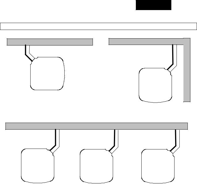
CLEARANCES |
|
|
|
Clearances (various examples) |
|
Wall |
|
Wall |
6” |
|
24” |
(152.4) |
|
|
|
|
(609.6) |
24” |
12” |
Service |
|
||
(609.6) |
(304.8) |
|
Service |
|
|
|
|
12” |
|
|
(304.8) |
12” |
|
|
(304.8) |
|
|
|
|
12” |
12 |
|
(304.8) |
|
|
|
|
Wall |
|
24” |
24” |
24” |
(609.6) |
(609.6) |
(609.6) |
Service |
Service |
Service |
18” |
18” |
18” |
(457.2) |
(457.2) |
(457.2) |
6”
(152.4)
Wall
Note: Numbers in ( ) = mm
Loading...