


 Loading...
581J
GAS HEAT/ELECTRIC COOLING PACKAGED ROOFTOP
3 to 8.5 NOMINAL TONS
Product Data
TM
C10405
the environmentally sound refrigerant
C10222
E2010 Bryant Heating & Cooling Systems D 7310 W. Morris St. D Indianapolis, IN 46231 |
Printed in U.S.A. |
Edition Date: 4/10 |
Catalog No.PDS581J---01 |
Manufacturer reserves the right to discontinue, or change at any time, specifications or designs without notice and without incurring obligations. |
Replaces: NEW |
581J
TABLE OF CONTENTS
|
PAGE |
|
PAGE |
FEATURES AND BENEFITS . . . . . . . . . . . . . . . . . |
. . . 3 |
SELECTION PROCEDURE . . . . . . . . . . . . . . . . . . . |
. . 25 |
MODEL NUMBER NOMENCLATURE . . . . . . . . . |
. . . 4 |
COOLING TABLES . . . . . . . . . . . . . . . . . . . . . . . . . |
. . 26 |
FACTORY OPTIONS AND/OR ACCESSORIES . . |
. . . 6 |
STATIC PRESSURE ADDERS . . . . . . . . . . . . . . . . |
. . 32 |
AHRI COOLING RATING TABLES . . . . . . . . . . . . |
. . . 8 |
FAN PERFORMANCE . . . . . . . . . . . . . . . . . . . . . . . |
. . 33 |
HEAT RATING TABLE . . . . . . . . . . . . . . . . . . . . . . |
. . . 9 |
OUTDOOR AIR INTAKE & EXHAUST PERF . . . . . 43 |
|
SOUND PERFORMANCE TABLE . . . . . . . . . . . . . |
. . 10 |
ELECTRICAL INFORMATION . . . . . . . . . . . . . . . |
. . 44 |
PHYSICAL DATA . . . . . . . . . . . . . . . . . . . . . . . . . . . |
. . 12 |
MCA/MOCP . . . . . . . . . . . . . . . . . . . . . . . . . . . . . . . |
. . 46 |
CURBS & WEIGHTS DIMENSIONS . . . . . . . . . . . |
. . 16 |
TYPICAL WIRING DIAGRAMS . . . . . . . . . . . . . . |
. . 51 |
APPLICATION DATA . . . . . . . . . . . . . . . . . . . . . . . |
. . 23 |
SEQUENCE OF OPERATION . . . . . . . . . . . . . . . . . |
. . 55 |
|
|
GUIDE SPECIFICATIONS . . . . . . . . . . . . . . . . . . . . |
. . 57 |
Your Bryant rooftop unit (RTU) was designed by customers for customers. With “no-strip screw” collars, handled access panels, and more we’ve made your unit easy to install, easy to maintain and easy to use.
Easy to install:
All Preferred Seriest units are field-convertible to horizontal air flow; no special adapter curbs or kits are necessary. Convertible airflow design makes it easy to adjust to unexpected job-site complications. Lighter units make easy replacement. Bryant 3-8.5 ton 581J rooftops fit on existing Bryant curbs dating back to 1989. Also, our large control box gives you room to work and room to mount Bryant accessory controls.
Easy to maintain:
Easy access handles by Bryant provide quick and easy access to all normally serviced components. Our “no-strip” screw system has superior holding power and guides screws into position while preventing the screw from stripping the unit’s metal. Take accurate pressure readings by reading condenser pressure with panels on. Simply remove the black, composite plug, route your gauge line(s) through the hole, and connect them to the refrigeration service valve(s). Now, you can take refrigeration system pressure readings without affecting the condenser airflow.
Easy to use:
The newly designed, master terminal board by Bryant puts all your connections and troubleshooting points in one convenient place, standard. Most low voltage connections are made to the same board and make it easy to find what you’re looking for and easy to access it. Bryant rooftops have high and low pressure switches, a filter drier, and 2” (51mm) filters standard.
the environmentally sound refrigerant
2

FEATURES AND BENEFITS
S Single-stage cooling capacity control on 04 to 07 models
S Two-stage cooling capacity control on 08 and 09 models
S SEER up to 15.6
S EER up to 13.0
S IEER’s up to 13.0
SExclusive non-corrosive composite condensate pan in accordance with ASHRAE 62 Standard, sloping design; side or center drain
S Gas efficiencies up to 82%
S Induced draft combustion design
S Redundant gas valve, with up to 2 stages of heating
S Pre-painted exterior panels and primer-coated interior panels tested to 500 hours salt spray protection S TXV refrigerant metering system on each circuit
S Fully insulated cabinet
SExclusive IGC solid-state control for on-board diagnostics with LED error code designation, burner control logic and energy saving indoor fan motor delay
SDedicated 3-5 ton “Low NOx” models available that meet California Air Quality Management NOx requirement of 40 nangram/joule or less. Low NOx models include stainless steel heat exchangers
S Cooling operating range up to 125_F (52_C), and down to 35_F (2_C) standard S Access panels with easy grip handles
S Innovative , easy starting, no-strip screw feature on unit access panels S Two-inch disposable return air filters
S Tool-less filter access door
S Belt drive evaporator-fan motor and pulley combinations available on all three phase models S Electric Drive x13 (5 speed/torque) motor on 04 to 06 models
S New terminal board facilitating simple safety circuit troubleshooting and simplified control box arrangement S Field Convertible from vertical to horizontal airflow for slab mounting. No special kits required
S Provisions for thru-the-bottom power entry capability as standard S Single point gas and electric connections
S Full perimeter base rail with built-in rigging adapters and fork truck slots S Scroll compressors with internal line-break overload protection
S 24-volt control circuit protected with resettable circuit breaker S Permanently lubricated evaporator-fan motor
S Totally enclosed condenser motors with permanently lubricated bearings S Low Pressure switch and high-pressure switch protection
S Exclusive IGC anti-cycle protection for gas heat operation S Solid-state electronic direct spark ignition system
S Flame roll-out safety protector
S Liquid line filter drier on each circuit
S Standard Warranty: 10 yr. aluminized heat exchanger, 15 yr. stainless steel heat exchanger, 5 yr. compressor, 1 yr. parts.
581J
3
581J
MODEL NUMBER NOMENCLATURE
1 |
2 |
3 |
4 |
5 |
6 |
7 |
8 |
9 |
10 |
11 |
12 |
13 |
14 |
15 |
16 |
17 |
18 |
|
|
|
|
|
|
|
|
|
|
|
|
|
|
|
|
|
|
5 |
8 |
1 |
J |
E |
0 |
6 |
A |
0 |
7 |
2 |
A |
0 |
A |
0 |
A |
A |
-- |
|
|
|
|
|
|
|
|
|
|
|
|
|
|
|
|
|
|
|
____________ |
|
______ |
|
________ |
|
|
|
______ |
|
|
||||||
Unit Type
581J = Cooling/Gas Heat RTU Legacy Series w/Puron Refrigerant
Voltage |
|
|
|
E = 460--- |
3--- |
60 |
|
J = 208/230--- |
1--- |
60 |
|
P = 208/230--- |
3--- |
60 |
|
T = 575--- |
3--- |
60 |
|
Cooling Tons
04 = 3 Ton
05 = 4 Ton
06 = 5 Ton
07 = 6 Ton
08 = 7.5 Ton
09 = 8.5 Ton
Refrig. System/Gas Heat Options
A= 1---Stage Cooling/Nat gas heat
B= 1---Stage Cooling/Low NOx heat
C= 1---Stage CoolingSS HX
D= 2---Stage Cooling 08---09
F = 2---Stage Cooling/SS HX
Heat Level (Input)
Standard/Stainless Steel 072 = 72,000 115 = 115,000 125 = 125,000 150 = 150,000 180 = 180,000 224 = 224,000
Low NOx 060 = 60,000 090 = 90,000
120 = 120,000
Design Revision
--- --- First Revision
Packaging
A --- |
Standard |
B --- |
LTL |
Factory Installed Options
Outdoor Air Options
A = None
B = Temp econo w/ baro relief
E = Temp econo w/ baro relief & CO2
H = Enthalpy econo w/ baro relief
L = Enthalpy econo w/ baro relief & CO2
Q = Motorized 2 pos damper
Indoor Fan Options
1 = Standard static option
2 = Medium static option
3 = High static option
Coil Options (outdoor |
---indoor--- |
hail guard) |
|||
A = Al/Cu --- |
Al/Cu |
|
|
|
|
B = Precoat Al/Cu --- |
Al/Cu |
|
|
||
C = E---coat Al/Cu --- |
Al/Cu |
|
|
||
D = E---coat Al/Cu --- |
E--- |
coat Al/Cu |
|||
E = Cu/Cu --- |
Al/Cu |
|
|
|
|
F = Cu/Cu --- |
Cu/Cu |
|
|
|
|
M = Al/Cu --- |
Al/Cu --- |
Louvered Hail guards |
|||
N = Precoat Al/Cu --- |
Al/Cu |
--- Louvered Hail Guards |
|||
P = E coat Al/Cu --- |
Al/Cu --- |
Louvered Hail Guards |
|||
Q = E coat Al/Cu --- |
E coat Al/Cu |
--- Louvered Hail Guards |
|||
R = Cu/Cu --- |
Al/Cu |
--- Louvered Hail Guards |
|||
S = Cu/Cu --- |
Cu/Cu --- |
Louvered Hail Guards |
|||
4
TABLE 1 – FACTORY-INSTALLED OPTIONS AND FIELD-INSTALLED ACCESSORIES
CATEGORY |
ITEM |
FACTORY |
FIELD |
|
|
INSTALLED |
INSTALLED |
|
|
||
|
|
OPTION |
ACCESSORY |
|
|
|
|
|
|
|
|
Cabinet |
Thru---the---base electrical or gas---line connections |
X |
X |
|
|
Hinged access panels |
X |
|
|
|
|
|
|
|
|
||
|
Cu/Cu indoor and/or outdoor coils |
X |
|
|
|
Coil Options |
|
|
|
|
|
Pre---coated outdoor coils |
X |
|
|
|
|
|
Premium, E---coated outdoor coils |
X |
|
|
|
Condenser Protection |
Condenser coil hail guard (louvered design) |
X |
X |
|
|
|
Thermostats, temperature sensors, and subbases |
|
X |
|
|
|
RTU---MP open---protocol controller |
X |
|
|
|
Controls |
|
|
|
|
|
Smoke detector (supply and/or return air) |
X |
|
|
|
|
|
|
|
|
|
|
|
Time Guard II compressor delay control circuit |
|
X |
|
|
|
Phase Monitor |
|
X |
|
|
|
|
|
|
||
|
|
|
|
|
|
|
EconoMi$ert IV (for electro---mechanical controlled RTUs) |
X |
X |
|
581J |
Economizers |
EconoMi$ert2 (for DDC controlled RTUs) |
X |
X |
|
|
& Outdoor Air |
Motorized 2 position outdoor---air damper |
X |
X |
|
|
Dampers |
Manual outdoor---air damper (25% and 50%) |
|
X |
|
|
|
|
|
|||
|
Barometric relief1 |
X |
X |
|
|
|
Power exhaust |
|
X |
|
|
|
|
|
|
|
|
|
Single dry bulb temperature sensors2 |
X |
X |
|
|
Economizer Sensors |
Differential dry bulb temperature sensors2 |
|
X |
|
|
Single enthalpy sensors2 |
X |
X |
|
|
|
& |
|
|
|||
Differential enthalpy sensors2 |
|
X |
|
|
|
IAQ Devices |
|
|
|
||
|
Wall or duct mounted CO2 sensor2 |
|
X |
|
|
|
Unit mounted CO2 sensor2 |
X |
|
|
|
|
Propane conversion kit |
|
X |
|
|
|
Stainless steel heat exchanger |
X |
|
|
|
Gas Heat |
|
|
|
|
|
High altitude conversion kit |
|
X |
|
|
|
|
Flue Shield |
|
X |
|
|
|
Flue Discharge Deflector |
|
X |
|
|
|
|
|
|
|
|
Indoor Motor & Drive |
Multiple motor and drive packages |
X |
|
|
|
Low Ambient |
Winter start kit3 |
|
X |
|
|
Control |
Motormaster head pressure controller3 |
|
X |
|
|
Power |
Convenience outlet (powered) |
X |
|
|
|
Convenience outlet (unpowered) |
X |
|
|
|
|
Options |
|
|
|
||
|
|
|
|
|
|
Non---fused disconnect |
X |
|
|
|
|
|
|
|
|
||
|
|
|
|
|
|
Roof Curbs |
Roof curb 14” (356mm) |
|
X |
|
|
Roof curb 24” (610mm) |
|
X |
|
|
|
|
|
|
|
NOTES:
1.Included with economizer.
2.Sensors used to optimize economizer performance.
3.See application data for assistance.
5

581J
FACTORY OPTIONS AND/OR ACCESSORIES
Economizer (dry-bulb or enthalpy)
Economizers save money. They bring in fresh, outside air for ventilation; and provide cool, outside air to cool your building. This is the preferred method of low-ambient cooling. When coupled to CO2 sensors, economizers can provide even more savings by coupling the ventilation air to only that amount required.
Economizers are available, installed and tested by the factory, with either enthalpy or dry-bulb temperature inputs. There are also models for electromechanical as well as direct digital controllers. Additional sensors are available as accessories to optimize the economizers.
Economizers include gravity controlled, barometric relief equalizes building pressure and ambient air pressures. This can be a cast effective solution to prevent building pressurization.
CO2 Sensor
Improves productivity and saves money by working with the economizer to intake only the correct amount of outside air for ventilation. As occupants fill your building, the CO2 sensor detects their presence through increasing CO2 levels, and opens the economizer appropriately.
When the occupants leave, the CO2 levels decrease, and the sensor appropriately closes the economizer. This intelligent control of the ventilation air, called Demand Control Ventilation (DCV) reduces the overall load on the rooftop, saving money.
Smoke Detectors
Trust the experts. Smoke detectors make your application safer and your job easier. Bryant smoke detectors immediately shut down the rooftop unit when smoke is detected. They are available, installed by the factory, for supply air, return air, or both.
Louvered Hail Guards
Sleek, louvered panels protect the condenser coil from hail damage, foreign objects, and incidental contact.
Convenience Outlet (powered or un-powered)
Reduce service and/or installation costs by including a convenience outlet in your specification. Bryant will install this service feature at our factory. Provides a convenient, 15 amp, 115v GFCI receptacle with “Wet in Use” cover. The “powered” option allows the installer to power the outlet from the line side of the disconnect or load side as required by code. The “unpowered” option is to be powered from a separate 115/120v power source.
Non-fused Disconnect
This OSHA-compliant, factory-installed, safety switch allows a service technician to locally secure power to the rooftop.
Power Exhaust with Barometric Relief
Superior internal building pressure control. This field-installed accessory may eliminate the need for costly, external pressure control fans.
RTU-MP, Multi-Protocol Controller
Connect the rooftop to an existing BAS without needing complicated translators or adapter modules using the RTU-MP controller. This new controller speaks the 4 most common building automation system languages (Bacnet, Modbus, N2, and Lonworks). Use this controller when you have an existing BAS.
Time Guard II Control Circuit
This accessory protects your compressor by preventing short-cycling in the event of some other failure, prevents the compressor from restarting for 30 seconds after stopping. Not required with RTU-MP or authorized commercial thermostats.
Motorized 2-Position Damper
The new Bryant 2-position, motorized outdoor air damper admits up to 100% outside air. Using reliable, gear-driven technology, the 2-position damper opens to allow ventilation air and closes when the rooftop stops, stopping unwanted infiltration.
Manual OA Damper
Manual outdoor air dampers are an economical way to bring in ventilation air. The dampers are available in 25% and 50% versions.
Hinged Access Panels
Allows access to unit’s major components with specifically designed hinged access panels. Panels are: filter, control box, fan motor and compressor.
6

FACTORY OPTIONS AND/OR ACCESSORIES (CON’T)
Motormaster Head Pressure Controller
The Motormaster motor controller is a low ambient, head pressure controller kit that is designed to maintain the unit’s condenser head pressure during periods of low ambient cooling operation. This device should be used as an alternative to economizer free cooling not when economizer usage is either not appropriate or desired. The Motormaster will either cycle the outdoor-fan motors or operate them at reduced speed to maintain the unit operation, depending on the model.
Winter Start Kit
The winter start kit by Bryant extends the low ambient limit of your rooftop to 25_F (-4_C). The kit bypasses the low pressure switch, preventing nuisance tripping of the low pressure switch. Other low ambient precautions may still be prudent.
Propane Heating
Convert your gas heat rooftop from standard natural gas operation to Propane using this field-installed kit.
High Altitude Heating
High altitudes have less oxygen, which means heat exchangers need less fuel. The new gas orifices in this field-installed kit make the necessary adjustment for high altitude applications. They restore the optimal fuel to air mixture and maintain healthy combustion at altitudes above 2000 ft (610m). Kits may not be required in all areas.
Flue Discharge Deflector
The flue discharge deflector is a useful accessory when flue gas recirculation is a concern. By venting the flue discharge upwards, the deflector minimizes the chance for a neighboring unit to intake the flue exhaust.
Optional Stainless Steel Heat Exchanger
The stainless steel heat exchanger option provides the tubular heat exchanger be made out of a minimum 20 gauge type 409 stainless steel for applications where the mixed air to the heat exchanger is expected to drop below 45_F (7_C). Stainless steel may be specified on applications where the presence of airborne contaminants require its use (applications such as paper mills) or in area with very high outdoor humidity that may result in severe condensation in the heat exchanger during cooling operation.
Flue Discharge Heat Shield
The flue discharge heat shield keeps people from touching the rooftop unit’s potentially hot flue discharge. This is especially useful for ground level applications, where more, untrained people could have access to the unit’s exterior.
Alternate Motors and Drives
Some applications need larger horsepower motors, some need more airflow, and some need both. Regardless of the case, your Bryant expert has a factory installed combination to meet your application. A wide selection of motors and pulleys (drives) are available, factory installed, to handle nearly any application.
Thru-the-Base Connections
Thru-the-base connections, available as either an accessory or as a factory option, are necessary to ensure proper connection and seal when routing wire and piping through the rooftop’s basepan and curb. These couplings eliminate roof penetration and should be considered for gas lines, main power lines, as well as control power.
581J
7
581J
TABLE 2 – AHRI COOLING RATING TABLE 1-STAGE COOLING
|
|
NOM. |
NET |
|
|
|
|
|
|
COOLING |
COOLING |
TOTAL |
|
|
|
||
UNIT |
CAPACITY |
SEER |
EER |
IEER |
||||
STAGES |
CAPACITY |
POWER (kW) |
||||||
|
(TONS) |
|
|
|
||||
|
|
(MBH) |
|
|
|
|
||
|
|
|
|
|
|
|
||
|
|
|
|
|
|
|
|
|
04A |
1 |
3 |
36.0 |
2.9 |
15.00 |
12.50 |
N/A |
|
05A |
1 |
4 |
48.5 |
3.7 |
15.60 |
13.00 |
N/A |
|
06A |
1 |
5 |
57.5 |
4.6 |
15.20 |
12.45 |
N/A |
|
07A |
1 |
6 |
73.0 |
6.0 |
N/A |
12.00 |
13.00 |
|
|
|
|
|
|
|
|
|
TABLE 3 – AHRI COOLING RATING TABLE 2-STAGE COOLING
|
|
NOM. |
NET |
|
|
|
|
|
|
COOLING |
COOLING |
TOTAL |
|
|
|
||
UNIT |
CAPACITY |
SEER |
EER |
IEER |
||||
STAGES |
CAPACITY |
POWER (kW) |
||||||
|
(TONS) |
|
|
|
||||
|
|
(MBH) |
|
|
|
|
||
|
|
|
|
|
|
|
||
|
|
|
|
|
|
|
|
|
08D |
2 |
7.5 |
89.0 |
7.4 |
N/A |
12.00 |
13.00 |
|
09D |
2 |
8.5 |
97.0 |
8.1 |
N/A |
12.00 |
13.00 |
|
|
|
|
|
|
|
|
|
LEGEND |
|
AHRI |
--- Air Conditioning, Heating and Refrigeration |
|
Institute Test Standard |
ASHRAE |
--- American Society of Heating, Refrigerating |
|
and Air Conditioning, Inc. |
EER |
--- Energy Efficiency Ratio |
IEER |
--- Integrated Energy Efficiency Ratio |
SEER |
--- Seasonal Energy Efficiency Ratio |
Use of the AHRI Certified TM Mark indicates a manufacturer’s participation in the program For verification
of certification for individual products, go to www.ahridirectory.org.
NOTES:
1.Rated in accordance with AHRI Standards 210/240 (04---06 size) and 340/360 (07---09 size).
2.Ratings are based on:
Cooling Standard: 80_F (27_C) db, 67_F (19_C) wb indoor air temp and 95_F (35_C) db outdoor air temp. IEER Standard: A measure that expresses cooling part---load EER efficiency for commercial unitary air---
conditioning and heat pump equipment on the basis of weighted operation at various load capacities.
3.All 581J units comply with ASHRAE 90.1 2001, 2004 Energy Standard for minimum SEER and EER requirements.
4.581J units comply with US Energy Policy Act (2005). To evaluate code compliance requirements, refer to state and local codes or visit the following website: http://bcap---energy.org.
8

TABLE 4 – HEATING RATING TABLE - NATURAL GAS & PROPANE
|
|
|
|
AL/SS HEAT EXCHANGER |
|
TEMP RISE |
THERMAL |
AFUE |
||||
Units |
Gas Heat |
|
|
|
|
|
EFFICIENCY |
|||||
INPUT / OUTPUT |
INPUT / OUTPUT |
(DEG F) |
(%) |
|||||||||
|
|
|
(%) |
|||||||||
|
|
|
STAGE 1 (MBH) |
STAGE 2 (MBH) |
|
|
|
|||||
|
|
|
|
|
|
|
||||||
|
|
|
|
|
|
|
|
|
|
|
|
|
|
|
LOW |
50 |
/ 41 |
72 |
/ |
59 |
25 |
--- 55 |
82% |
81% |
|
|
04 |
MED |
82 |
/ 66 |
115 / 93 |
55 |
--- 85 |
80% |
80% |
|||
Phase |
|
HIGH |
|
--- |
|
--- |
|
|
--- |
--- |
--- |
|
|
|
|
|
|
|
|
|
|
|
|
||
|
|
LOW |
50 |
/ 41 |
72 |
/ |
59 |
25 |
--- 55 |
82% |
81% |
|
Single |
05 |
MED |
82 |
/ 66 |
115 / 93 |
35 |
--- 65 |
81% |
80% |
|||
|
HIGH |
120 / 96 |
150 |
/ |
120 |
50 |
--- 80 |
80% |
80% |
|||
|
|
|||||||||||
|
|
|
|
|
|
|
|
|
|
|
|
|
|
|
LOW |
50 |
/ 41 |
72 |
/ |
59 |
20 |
--- 55 |
82% |
81% |
|
|
06 |
MED |
82 |
/ 66 |
115 / 93 |
30 |
--- 65 |
81% |
80% |
|||
|
|
HIGH |
120 / 96 |
150 |
/ |
120 |
40 |
--- 80 |
80% |
80% |
||
|
|
|
|
|
|
|
|
|
|
|
|
|
|
|
LOW |
50 |
/ 41 |
72 |
/ |
59 |
25 |
--- 55 |
82% |
N/A |
|
|
04 |
MED |
82 |
/ 66 |
115 / 93 |
55 |
--- 85 |
80% |
N/A |
|||
|
|
HIGH |
|
--- |
|
--- |
|
|
--- |
--- |
--- |
|
|
|
|
|
|
|
|
|
|
|
|
|
|
|
|
LOW |
50 |
/ 41 |
72 |
/ |
59 |
25 |
--- 55 |
82% |
N/A |
|
|
05 |
MED |
82 |
/ 66 |
115 / 93 |
35 |
--- 65 |
81% |
N/A |
|||
|
|
HIGH |
120 / 96 |
150 |
/ |
120 |
50 |
--- 80 |
80% |
N/A |
||
|
|
|
|
|
|
|
|
|
|
|
|
|
Phase |
|
LOW |
50 |
/ 41 |
72 |
/ |
59 |
20 |
--- 55 |
82% |
N/A |
|
06 |
MED |
82 |
/ 66 |
115 / 93 |
30 |
--- 65 |
81% |
N/A |
||||
|
||||||||||||
|
|
HIGH |
120 / 96 |
150 |
/ |
120 |
40 |
--- 80 |
80% |
N/A |
||
|
|
|
|
|
|
|
|
|
|
|
|
|
Three |
|
LOW |
50 |
/ 41 |
72 |
/ |
59 |
15 |
--- 55 |
82% |
N/A |
|
07 |
MED |
90 |
/ 73 |
125 |
/ |
103 |
20 |
--- 50 |
82% |
N/A |
||
|
||||||||||||
|
|
HIGH |
105 / 84 |
150 |
/ |
120 |
30 |
--- 60 |
81% |
N/A |
||
|
|
|
|
|
|
|
|
|
|
|
|
|
|
|
LOW |
90 |
/ 73 |
125 |
/ |
103 |
20 |
--- 50 |
82% |
N/A |
|
|
08 |
MED |
120 / 98 |
180 |
/ |
148 |
35 |
--- 65 |
82% |
N/A |
||
|
|
HIGH |
180 |
/ 147 |
224 |
/ |
184 |
45 |
--- 75 |
82% |
N/A |
|
|
|
|
|
|
|
|
|
|
|
|
|
|
|
|
LOW |
90 |
/ 73 |
125 |
/ |
103 |
20 |
--- 50 |
82% |
N/A |
|
|
09 |
MED |
120 / 98 |
180 |
/ |
148 |
30 |
--- 65 |
82% |
N/A |
||
|
|
HIGH |
180 |
/ 147 |
224 |
/ |
184 |
40 |
--- 75 |
82% |
N/A |
|
NOTES:
Heat ratings are for natural gas heat exchangers operated at or below 2000 ft (610 m). For information on Propane or altitudes above 2000 ft (610 m), see the Application Data section of this book. Accessory Propane/High Altitude kits are also available.
In the USA the input rating for altitudes above 2000 ft (610m) must be derated by 4% for each 1000 ft (305 m) above sea level. In Canada, the input rating must be derated by 10% for altitudes of 2000 ft (610 m) to 4500 ft (1372 m) above sea level.
581J
9

TABLE 5 – HEATING RATING TABLE - LOW NOX1
|
|
|
|
|
|
LOW NOx HEAT EXCHANGER |
TEMP RISE |
THERMAL |
AFUE |
|||
|
|
|
UNIT |
GAS HEAT |
|
|
|
EFFICIENCY |
||||
|
|
|
INPUT / OUTPUT |
INPUT / OUTPUT |
(DEG F) |
(%) |
||||||
|
|
|
|
|
|
(%) |
||||||
|
|
|
|
|
|
STAGE 1 (MBH) |
STAGE 2 (MBH) |
|
|
|
||
|
|
|
|
|
|
|
|
|
|
|||
|
|
|
|
|
|
|
|
|
|
|
|
|
|
|
|
|
|
LOW |
--- |
60 |
/ 50 |
20 |
--- 50 |
81% |
80% |
|
|
|
|
04 |
MED |
--- |
90 |
/ 74 |
30 |
--- 60 |
81% |
81% |
|
|
Phase |
|
|
HIGH |
--- |
|
--- |
|
--- |
--- |
--- |
|
|
|
|
|
|
|
|
|
|
|
|
|
|
|
|
|
|
LOW |
--- |
60 |
/ 50 |
20 |
--- 50 |
81% |
80% |
|
|
Single |
|
05 |
MED |
--- |
90 |
/ 74 |
30 |
--- 60 |
81% |
81% |
|
|
|
|
HIGH |
--- |
120 |
/ 101 |
40 |
--- 70 |
81% |
80% |
|
|
|
|
|
|
||||||||
|
|
|
|
|
|
|
|
|
|
|
|
|
|
|
|
|
|
LOW |
--- |
60 |
/ 50 |
15 |
--- 50 |
81% |
80% |
|
|
|
|
06 |
MED |
--- |
90 |
/ 74 |
25 |
--- 60 |
80% |
81% |
|
|
|
|
|
HIGH |
--- |
120 |
/ 101 |
35 |
--- 70 |
80% |
81% |
|
|
|
|
|
|
|
|
|
|
|
|
|
|
|
|
|
|
LOW |
--- |
60 |
/ 50 |
20 |
--- 50 |
81% |
80% |
|
|
|
|
04 |
MED |
--- |
90 |
/ 74 |
30 |
--- 60 |
81% |
81% |
|
|
PhaseThree |
|
|
HIGH |
--- |
|
--- |
|
--- |
--- |
--- |
581J |
|
|
|
|
|
|||||||
|
|
|
|
|
|
|
|
|
|
|
||
|
|
|
|
|
LOW |
--- |
60 |
/ 50 |
20 |
--- 50 |
81% |
80% |
|
|
|
|
05 |
MED |
--- |
90 |
/ 74 |
30 |
--- 60 |
81% |
81% |
|
|
|
|
|
HIGH |
--- |
120 |
/ 101 |
40 |
--- 70 |
81% |
80% |
|
|
|
|
|
|
|
|
|
|
|
|
|
|
|
|
|
06 |
LOW |
--- |
60 |
/ 50 |
15 |
--- 50 |
81% |
80% |
|
|
|
|
|||||||||
|
|
|
|
MED |
--- |
90 |
/ 74 |
25 |
--- 60 |
80% |
81% |
|
|
|
|
|
|
HIGH |
--- |
120 |
/ 101 |
35 |
--- 70 |
80% |
81% |
|
|
|
|
|
|
|
|
|
|
|
|
|
NOTE:
1.Units meet California’s South Coast Air Quality Management District (SCAQMD) Low---NOx emissions requirement of 40 nanograms per joule or less.
TABLE 6 – SOUND PERFORMANCE TABLE
UNIT |
COOLING |
|
|
|
OUTDOOR SOUND (dB) AT 60 |
|
|
|
|||
STAGES |
A---WEIGHTED |
63 |
125 |
|
250 |
500 |
1000 |
2000 |
4000 |
8000 |
|
|
|
||||||||||
04A |
1 |
76 |
78.2 |
78.0 |
|
74.2 |
73.3 |
70.6 |
66.0 |
62.4 |
56.9 |
05A |
1 |
78 |
84.7 |
83.6 |
|
77.1 |
74.6 |
72.3 |
68.3 |
64.7 |
60.9 |
|
|
|
|
|
|
|
|
|
|
|
|
06A |
1 |
77 |
87.5 |
82.5 |
|
76.1 |
73.6 |
71.3 |
67.1 |
64.1 |
60.0 |
07A |
1 |
82 |
90.1 |
82.6 |
|
81.0 |
79.4 |
77.0 |
73.0 |
70.4 |
66.7 |
08D |
2 |
82 |
90.6 |
84.3 |
|
80.2 |
79.3 |
77.1 |
72.2 |
67.4 |
63.7 |
09D |
2 |
82 |
88.6 |
85.0 |
|
81.6 |
79.5 |
77.4 |
74.1 |
71.0 |
66.3 |
|
|
|
|
|
|
|
|
|
|
|
|
LEGEND
dB --- Decibel
Use of the AHRI Certified TM Mark indicates a manufacturer’s participation in the program For verification
of certification for individual products, go to www.ahridirectory.org.
NOTES:
1.Outdoor sound data is measure in accordance with AHRI.
2.Measurements are expressed in terms of sound power. Do not compare these values to sound pressure values because sound pressure depends on specific environmental factors which normally do not match individual applications. Sound power values are independent of the environment and therefore more accurate.
3.A---weighted sound ratings filter out very high and very low frequencies, to better approximate the response of “average” human ear. A---weighted measurements for Bryant units are taken in accordance with AHRI.
10
TABLE 7 – MINIMUM - MAXIMUM AIRFLOW RATINGS - NATURAL GAS & PROPANE
UNIT |
HEAT LEVEL |
|
COOLING |
|
HEATING |
|
|
||
|
|
|
|
|
|
|
|
||
MINIMUM |
|
MAXIMUM |
MINIMUM |
|
MAXIMUM |
|
|
||
|
|
|
|
|
|
||||
|
LOW |
|
|
|
990 |
|
2190 |
|
|
581J*04 |
MED |
900 |
|
1500 |
1000 |
|
1550 |
|
|
|
HIGH |
|
|
|
--- |
|
--- |
|
|
|
|
|
|
|
|
|
|
|
|
|
LOW |
|
|
|
990 |
|
2190 |
|
|
581J*05 |
MED |
1200 |
|
2000 |
1330 |
|
2460 |
|
|
|
HIGH |
|
|
|
1390 |
|
2220 |
|
|
|
|
|
|
|
|
|
|
|
|
|
LOW |
|
|
|
990 |
|
2730 |
|
|
581J*06 |
MED |
1500 |
|
2500 |
1330 |
|
2880 |
|
|
|
HIGH |
|
|
|
1390 |
|
2780 |
|
|
|
|
|
|
|
|
|
|
|
|
|
LOW |
|
|
|
990 |
|
3640 |
|
|
581J*07 |
MED |
1800 |
|
3000 |
1330 |
|
4750 |
|
|
|
HIGH |
|
|
|
1390 |
|
3750 |
|
|
|
|
|
|
|
|
|
|
|
|
|
LOW |
|
|
|
1900 |
|
4750 |
|
|
|
|
|
|
|
|
|
|||
581J*08 |
MED |
2250 |
|
3750 |
2100 |
|
3900 |
|
581J |
|
HIGH |
|
|
|
2270 |
|
3780 |
|
|
|
|
|
|
|
|
|
|||
|
|
|
|
|
|
|
|
|
|
|
LOW |
|
|
|
1900 |
|
4750 |
|
|
581J*09 |
MED |
2550 |
|
4250 |
2100 |
|
4560 |
|
|
|
|
|
|
||||||
|
HIGH |
|
|
|
2270 |
|
4250 |
|
|
|
|
|
|
|
|
|
|
|
|
11

TABLE 8 – PHYSICAL DATA
|
|
Refrigeration System |
|
|||
|
|
|
|
|
|
# Circuits / # Comp. / Type |
|
|
|
|
Puronr refrig. (R---410A) charge A/B (lbs---oz) |
||
|
|
|
|
|
|
Metering Device |
|
|
|
|
|
|
High---press. Trip / Reset (psig) |
|
|
|
|
|
|
Low---press. Trip / Reset (psig) |
|
|
Evap. Coil |
Compressor Capacity Staging (%) |
|||
|
|
|
||||
|
|
|
|
|
|
Material (Tube Fin) |
|
|
|
|
|
|
Coil type |
|
|
|
|
|
|
Rows / FPI |
|
|
|
|
|
|
Total Face Area (ft2) |
|
|
Evap. Fan and Motor |
Condensate Drain Conn. Size |
|||
|
|
|
||||
|
|
|
|
|
|
Motor Qty / Drive Type |
581J |
|
|
StaticStandard |
phase1 |
|
|
|
|
|
Max BHP |
|||
|
|
|
|
|
|
|
|
|
|
|
|
|
RPM Range |
|
|
|
|
|
|
Motor Frame Size |
|
|
|
|
|
|
Fan Qty / Type |
|
|
|
|
|
|
Fan Diameter (in) |
|
|
|
|
|
|
Motor Qty / Drive Type |
|
|
|
|
|
|
|
|
|
|
StaticStandard |
phase3 |
|
|
|
|
|
|
Max BHP |
||
|
|
|
|
|
|
|
|
|
|
|
|
|
RPM Range |
|
|
|
|
|
|
Motor Frame Size |
|
|
|
|
|
|
Fan Qty / Type |
|
|
|
|
|
|
Fan Diameter (in) |
|
|
|
|
|
|
Motor Qty / Drive Type |
|
|
|
|
|
|
|
|
|
|
StaticMedium |
phase3 |
|
|
|
|
|
|
Max BHP |
||
|
|
|
|
|
|
|
|
|
|
|
|
|
RPM Range |
|
|
|
|
|
|
Motor Frame Size |
|
|
|
|
|
|
Fan Qty / Type |
|
|
|
|
|
|
Fan Diameter (in) |
|
|
|
|
|
|
Motor Qty / Drive Type |
|
|
|
|
|
|
|
|
|
|
|
|
|
|
|
|
|
HighStatic |
phase3 |
|
Max BHP |
|
|
|
|
Fan Qty / Type |
||
|
|
|
|
|
|
RPM Range |
|
|
|
|
|
|
Motor Frame Size |
|
|
|
|
|
|
Fan Diameter (in) |
|
|
|
|
|
|
|
|
|
Cond. Coil |
|
|||
|
|
|
|
|
|
Material (Tube/Fin) |
|
|
|
|
|
|
Coil type |
|
|
|
|
|
|
Rows / FPI |
|
|
Cond. fan / motor |
Total Face Area (ft2) |
|||
|
|
|
||||
|
|
|
|
|
|
Qty / Motor Drive Type |
|
|
|
|
|
|
Motor HP / RPM |
|
|
Filters |
|
|
Fan diameter (in) |
|
|
|
|
|
|
||
|
|
|
|
|
|
RA Filter # / Size (in) |
|
|
|
|
|
|
OA inlet screen # / Size (in) |
|
|
|
|
|
|
|
(COOLING) |
|
|
|
|
3 - 6 TONS |
||||
|
581J*04A |
|
581J*05A |
|
581J*06A |
|
581J*07A |
|
|
|
|
|
|
|
|||||
|
|
|
|
|
|
|
|
|
|
|
1 / 1 / Scroll |
|
1 / 1 / Scroll |
|
1 / 1 / Scroll |
|
1 / 1 / Scroll |
|
|
|
9 --- 0 |
|
12 --- 8 |
|
13 --- 3 |
|
14 --- 0 |
|
|
|
TXV |
|
TXV |
|
TXV |
|
TXV |
|
|
|
630 / 505 |
|
630 / 505 |
|
630 / 505 |
|
630 / 505 |
|
|
|
54 / 117 |
|
54 / 117 |
|
54 / 117 |
|
54 / 117 |
|
|
|
100% |
|
100% |
|
100% |
|
100% |
|
|
|
Cu / Al |
|
Cu / Al |
|
Cu / Al |
|
Cu / Al |
|
|
|
3/8” RTPF |
|
3/8” RTPF |
|
3/8” RTPF |
|
3/8” RTPF |
|
|
|
3 / 15 |
|
3 / 15 |
|
4 / 15 |
|
3 / 15 |
|
|
|
5.5 |
|
7.3 |
|
7.3 |
|
8.9 |
|
|
|
3/4” |
|
3/4” |
|
3/4” |
|
3/4” |
|
|
|
1 / Direct |
|
1 / Direct |
|
1 / Direct |
|
n/a |
|
|
|
|
|
|
|
|
||||
|
1 |
|
1 |
|
1 |
|
n/a |
|
|
|
600---1200 |
|
600---1200 |
|
600---1200 |
|
n/a |
|
|
|
48 |
|
48 |
|
48 |
|
n/a |
|
|
|
1 / Centrifugal |
|
1 / Centrifugal |
|
1 / Centrifugal |
|
n/a |
|
|
|
10 x 10 |
|
10 x 10 |
|
11 x 10 |
|
n/a |
|
|
|
1 / Direct |
|
1 / Direct |
|
1 / Direct |
|
1 / Belt |
|
|
|
1 |
|
1 |
|
1 |
|
2.4 |
|
|
|
600---1200 |
|
600---1200 |
|
600---1200 |
|
1073---1457 |
|
|
|
48 |
|
48 |
|
48 |
|
56 |
|
|
|
1 / Centrifugal |
|
1 / Centrifugal |
|
1 / Centrifugal |
|
1 / Centrifugal |
|
|
|
10 x 10 |
|
10 x 10 |
|
11 x 10 |
|
10 x 10 |
|
|
|
1 / Belt |
|
1 / Belt |
|
1 / Belt |
|
1 / Belt |
|
|
|
1.2 |
|
1.7 |
|
2.4 |
|
2.9 |
|
|
|
770---1175 |
|
920---1303 |
|
1035---1466 |
|
1173---1518 |
|
|
|
48 |
|
56 |
|
56 |
|
56 |
|
|
|
1 / Centrifugal |
|
1 / Centrifugal |
|
1 / Centrifugal |
|
1 / Centrifugal |
|
|
|
10 x 10 |
|
10 x 10 |
|
10 x 10 |
|
10 x 10 |
|
|
|
1 / Belt |
|
1 / Belt |
|
1 / Belt |
|
1 / Belt |
|
|
|
2.4 |
|
2.9 |
|
2.9 |
|
3.7 |
|
|
|
1035---1466 |
|
1208---1639 |
|
1303---1687 |
|
1474---1788 |
|
|
|
56 |
|
56 |
|
56 |
|
56 |
|
|
|
1 / Centrifugal |
|
1 / Centrifugal |
|
1 / Centrifugal |
|
1 / Centrifugal |
|
|
|
10 x 10 |
|
10 x 10 |
|
10 x 10 |
|
10 x 10 |
|
|
|
Cu / Al |
|
Cu / Al |
|
Cu / Al |
|
Cu / Al |
|
|
|
3/8” RTPF |
|
3/8” RTPF |
|
3/8” RTPF |
|
3/8” RTPF |
|
|
|
2 / 17 |
|
2 / 17 |
|
2 / 17 |
|
2 / 17 |
|
|
|
12.7 |
|
21.3 |
|
21.3 |
|
20.5 |
|
|
|
1/ Direct |
|
1/ Direct |
|
1/ Direct |
|
2/ Direct |
|
|
|
1/8 / 825 |
|
1/4 / 1100 |
|
1/4 / 1100 |
|
1/4 / 1100 |
|
|
|
22 |
|
22 |
|
22 |
|
22 |
|
|
|
2 / 16 x 25 x 2 |
|
4 / 16 x 16 x 2 |
|
4 / 16 x 16 x 2 |
|
4 / 16 x 20 x 2 |
|
|
|
1 / 20 x 24 x 1 |
|
1 / 20 x 24 x 1 |
|
1 / 20 x 24 x 1 |
|
1 / 20 x 24 x 1 |
|
|
|
|
|
|
|
|
|
|
|
|
12
TABLE 9 – PHYSICAL DATA |
(HEATING) |
|
3 - 6 TONS |
|
|
|||
|
|
|
|
|
|
|
|
|
|
|
|
581J*04A |
581J*05A |
581J*06A |
581J*07A |
|
|
Gas Connection |
|
|
|
|
|
|
||
|
|
|
|
|
|
|||
|
|
# of Gas Valves |
1 |
1 |
1 |
1 |
|
|
|
Nat. gas supply line press (in. w.g.)/(PSIG) |
4 ---13 / 0.18 --- 0.47 |
4 ---13 / 0.18 --- 0.47 |
4 ---13 / 0.18 --- 0.47 |
4 ---13 / 0.18 --- 0.47 |
|
|
|
|
Propane supply line press (in. w.g.)/(PSIG) |
11 ---13 / 0.40 --- 0.47 |
11 ---13 / 0.40 --- 0.47 |
11 ---13 / 0.40 --- 0.47 |
11 ---13 / 0.40 --- 0.47 |
|
|
|
Heat Anticipator Setting (Amps) |
|
|
|
|
|
|
||
|
|
1st stage |
0.14 |
0.14 |
0.14 |
0.14 |
|
|
|
|
2nd stage |
0.14 |
0.14 |
0.14 |
0.14 |
|
|
|
|
|
|
|
|
|
|
|
Natural Gas, Propane Heat |
|
|
|
|
|
|
||
|
|
# of stages / # of burners (total) |
1 or 2 / 2 |
1 or 2 / 2 |
1 or 2 / 2 |
2 / 2 |
|
|
|
|
Connection size |
1/2” NPT |
1/2” NPT |
1/2” NPT |
1/2” NPT |
|
|
|
LOW |
|
|
|||||
|
Rollout switch opens / closes |
195 / 115 |
195 / 115 |
195 / 115 |
195 / 115 |
|
|
|
|
|
|
|
|||||
|
|
Temperature rise range (F) |
25 --- 55 |
25 --- 55 |
20 --- 55 |
15 --- 55 |
|
|
|
|
|
581J |
|||||
|
|
# of stages / # of burners (total) |
1 or 2 / 3 |
1 or 2 / 3 |
1 or 2 / 3 |
2 / 3 |
|
|
|
|
|
||||||
|
|
|
|
|||||
|
|
Connection size |
1/2” NPT |
1/2” NPT |
1/2” NPT |
1/2” NPT |
|
|
|
MED |
|
|
|||||
|
Rollout switch opens / closes |
195 / 115 |
195 / 115 |
195 / 115 |
195 / 115 |
|
|
|
|
|
Temperature rise range (F) |
55 --- 85 |
35 --- 65 |
30 --- 65 |
20 --- 50 |
|
|
|
|
Connection size |
--- |
1 or 2 / 3 |
1 or 2 / 3 |
2 / 4 |
|
|
|
|
|
|
|||||
|
|
# of stages / # of burners (total) |
--- |
1/2” NPT |
1/2” NPT |
3/4” NPT |
|
|
|
HIGH |
|
|
|||||
|
Rollout switch opens / closes |
--- |
195 / 115 |
195 / 115 |
195 / 115 |
|
|
|
|
|
|
|
|||||
|
|
Temperature rise range (F) |
--- |
50 --- 80 |
40 --- 80 |
30 --- 60 |
|
|
|
|
|
|
|
|
|
|
|
|
|
|
|
|
|
|
||
Low NOx Gas Heat |
|
|
|
|
|
|
||
|
|
# of stages / # of burners (total) |
1 or 2 / 2 |
1 or 2 / 2 |
1 or 2 / 2 |
--- |
|
|
|
|
Connection size |
1/2” NPT |
1/2” NPT |
1/2” NPT |
--- |
|
|
|
LOW |
|
|
|||||
|
Rollout switch opens / closes |
195 / 115 |
195 / 115 |
195 / 115 |
--- |
|
|
|
|
|
|
|
|||||
|
|
Temperature rise range (F) |
20 --- 50 |
20 --- 50 |
15 --- 50 |
--- |
|
|
|
|
# of stages / # of burners (total) |
1 or 2 / 3 |
1 or 2 / 3 |
1 or 2 / 3 |
--- |
|
|
|
|
|
|
|||||
|
|
Connection size |
1/2” NPT |
1/2” NPT |
1/2” NPT |
--- |
|
|
|
MED |
|
|
|||||
|
Rollout switch opens / closes |
195 / 115 |
195 / 115 |
195 / 115 |
--- |
|
|
|
|
|
|
|
|||||
|
|
Temperature rise range (F) |
30 --- 60 |
30 --- 60 |
25 --- 60 |
--- |
|
|
|
|
|
|
|
|
--- |
|
|
|
|
|
|
|
|
|
|
|
|
|
# of stages / # of burners (total) |
--- |
1 or 2 / 3 |
1 or 2 / 3 |
--- |
|
|
|
|
Connection size |
--- |
1/2” NPT |
1/2” NPT |
--- |
|
|
|
HIGH |
|
|
|||||
|
Rollout switch opens / closes |
--- |
195 / 115 |
195 / 115 |
--- |
|
|
|
|
|
|
|
|||||
|
|
Temperature rise range (F) |
--- |
40 --- 70 |
35 --- 70 |
--- |
|
|
|
|
|
|
|
|
|
|
|
|
|
|
|
|
|
|
|
|
13

TABLE 10 – PHYSICAL DATA
Refrigeration System
Evap. Coil
Evap. fan and motor
|
|
Standard Static |
|
581J |
|
3 phase |
|
|
|
|
|
|
|
|
|
|
|
|
|
|
|
|
|
|
|
Medium Static |
3 phase |
|
|
|
|
|
|
|
|
|
|
High Static |
3 phase |
|
|
|
|
Cond. Coil
Cond. fan / motor
Filters
(COOLING) |
|
|
|
7.5 - 8.5 TONS |
||
|
|
581J*08D |
|
581J*09D |
|
|
|
|
|
|
|||
|
|
|
|
|
|
|
# Circuits / # Comp. / Type |
|
2 / 2 / Scroll |
|
2 / 2 / Scroll |
|
|
|
|
|||||
R---410a charge A/B (lbs --- oz) |
|
9 --- 10 / 9 --- 10 |
|
9 --- 19 / 9 --- 14 |
|
|
Metering device |
|
TXV |
|
TXV |
|
|
High---press. Trip / Reset (psig) |
|
630 / 505 |
|
630 / 505 |
|
|
Low---press. Trip / Reset (psig) |
|
54 / 117 |
|
54 / 117 |
|
|
Compressor Capacity Staging (%) |
|
50% / 100% |
|
50% / 100% |
|
|
Material (Tube/Fin) |
|
Cu / Al |
|
Cu / Al |
|
|
|
|
|||||
Coil type |
|
3/8” RTPF |
|
3/8” RTPF |
|
|
Rows / FPI |
|
4 / 15 |
|
4 / 15 |
|
|
total face area (ft2) |
|
11.1 |
|
11.1 |
|
|
Condensate drain conn. size |
|
3/4” |
|
3/4” |
|
|
Motor Qty / Drive type |
|
1 / Belt |
|
1 / Belt |
|
|
|
|
|
|
|||
Max BHP |
|
1.7 |
|
1.7 |
|
|
RPM range |
|
518---733 |
|
518---733 |
|
|
motor frame size |
|
56 |
|
56 |
|
|
Fan Qty / Type |
|
1 / Centrifugal |
|
1 / Centrifugal |
|
|
Fan Diameter (in) |
|
15 x 15 |
|
15 x 15 |
|
|
Motor Qty / Drive type |
|
1 / Belt |
|
1 / Belt |
|
|
Max BHP |
|
2.4 |
|
2.4 |
|
|
RPM range |
|
690---936 |
|
690---936 |
|
|
motor frame size |
|
56 |
|
56 |
|
|
Fan Qty / Type |
|
1 / Centrifugal |
|
1 / Centrifugal |
|
|
Fan Diameter (in) |
|
15 x 15 |
|
15 x 15 |
|
|
Motor Qty / Drive type |
|
1 / Belt |
|
1 / Belt |
|
|
Max BHP |
|
3.7 |
|
3.7 |
|
|
RPM range |
|
838---1084 |
|
838---1084 |
|
|
motor frame size |
|
56 |
|
56 |
|
|
Fan Qty / Type |
|
1 / Centrifugal |
|
1 / Centrifugal |
|
|
Fan Diameter (in) |
|
15 x 15 |
|
15 x 15 |
|
|
Material (Tube/Fin) |
|
Cu / Al |
|
Cu / Al |
|
|
|
|
|
|
|||
|
|
|||||
Coil type |
|
3/8” RTPF |
|
3/8” RTPF |
|
|
Rows / FPI |
|
2 / 17 |
|
2 / 17 |
|
|
Total Face Area (ft2) |
|
25.1 |
|
25.1 |
|
|
Qty / Motor drive type |
|
2 / direct |
|
2 / direct |
|
|
|
|
|||||
Motor HP / RPM |
|
1/4 / 1100 |
|
1/4 / 1100 |
|
|
Fan diameter (in) |
|
22 |
|
22 |
|
|
RA Filter # / size (in) |
|
4 / 20 x 20 x 2 |
|
4 / 20 x 20 x 2 |
|
|
|
|
|||||
OA inlet screen # / size (in) |
|
1 / 20 x 24 x 1 |
|
1 / 20 x 24 x 1 |
|
|
|
|
|
|
|
|
|
14
TABLE 11 – PHYSICAL DATA |
(HEATING) |
|
7.5 - 8.5 TONS |
|
|
||||
|
|
|
|
|
|
|
|
|
|
|
|
|
|
|
|
581J*08D |
581J*09D |
|
|
Gas Connection |
|
|
|
|
|
|
|
||
|
# of Gas Valves |
|
1 |
1 |
|
|
|||
|
|
|
|
|
|
|
|||
|
|
|
Nat. gas supply line press (in. w.g.)/(PSIG) |
|
4 ---13 / 0.18 --- 0.47 |
4 ---13 / 0.18 --- 0.47 |
|
|
|
|
|
|
Propane supply line press (in. w.g.)/(PSIG) |
|
11 ---13 / 0.40 --- 0.47 |
11 ---13 / 0.40 --- 0.47 |
|
|
|
Heat Anticipator Setting (Amps) |
|
|
|
|
|
|
|||
|
|
|
|
1st stage |
|
0.14 |
0.14 |
|
|
|
|
|
|
2nd stage |
|
0.14 |
0.14 |
|
|
|
|
|
|
|
|
|
|
|
|
Natural Gas, Propane Heat |
|
|
|
|
|
|
|||
|
|
|
# of stages / # of burners (total) |
|
2 / 3 |
2 / 3 |
|
|
|
|
|
|
|
Connection size |
|
1/2” NPT |
1/2” NPT |
|
|
|
LOW |
|
|
|
|
|
|||
|
|
Rollout switch opens / closes |
|
195 / 115 |
195 / 115 |
|
|
||
|
|
|
|
|
|
||||
|
|
|
|
Temperature rise range (F) |
|
20 --- 50 |
20 --- 50 |
|
|
|
|
|
|
|
|
581J |
|||
|
|
|
# of stages / # of burners (total) |
|
2 / 4 |
2 / 4 |
|
||
|
|
|
|
|
|||||
|
|
|
|
|
|
||||
|
|
|
|
Connection size |
|
3/4” NPT |
3/4” NPT |
|
|
|
MED |
|
|
|
|
|
|||
|
|
Rollout switch opens / closes |
|
195 / 115 |
195 / 115 |
|
|
||
|
|
|
|
Temperature rise range (F) |
|
35 --- 65 |
30 --- 65 |
|
|
|
|
|
# of stages / # of burners (total) |
|
2 / 5 |
2 / 5 |
|
|
|
|
|
|
|
|
|
||||
|
|
|
|
Connection size |
|
3/4” NPT |
3/4” NPT |
|
|
|
HIGH |
|
|
|
|
|
|||
|
|
Rollout switch opens / closes |
|
195 / 115 |
195 / 115 |
|
|
||
|
|
|
|
|
|
||||
|
|
|
|
Temperature rise range (F) |
|
45 --- 75 |
40 --- 75 |
|
|
|
|
|
|
|
|
|
|
|
|
|
|
|
|
|
|
|
|
|
|
15

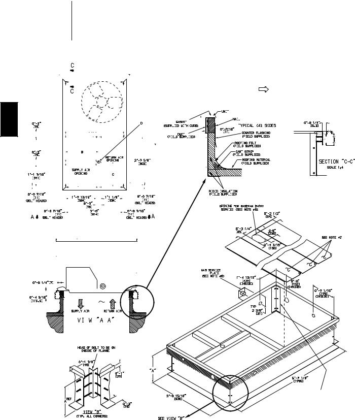
CURBS & WEIGHTS DIMENSIONS - 581J04-06
581J
|
|
K |
|
|
|
4-5/8 |
|
|
|
[118] |
|
|
|
ELECTRICAL |
|
|
|
DISCONNECT |
|
|
|
LOCATION |
|
CONDENSER |
A, |
||
COIL |
|
||
|
|
B, |
|
|
|
G |
|
OPTIONAL |
|
||
FACTORY |
19-1/2 |
||
INSTALLED |
|||
[494] |
|||
CONVENIENCE |
|||
D |
|||
OUTLET |
|||
|
|||
|
|
6-5/8 |
|
|
|
[168] |
|
3-3/4 |
|
|
|
[95] |
46-3/4 |
|
|
|
[1187] |
|
|
|
CONTROL BOX |
INDOOR BLOWER |
|
ACCESS PANEL |
ACCESS |
OPTIONAL |
|
|
FACTORY |
F |
HANDLE |
INSTALLED |
|
|
DISCONNECT |
|
|
|
HANDLE |
|
|
FRONT |
|
FILTER ACCESS PANEL |
|
|
(TOOL-LESS) |
COMP. |
CONDENSER |
|
ACCESS |
|
|
COIL |
|
|
PANEL |
|
|
|
|
INDOOR COIL |
|
|
ACCESS PANEL |
|
|
BACK |
2-5/8 |
[67] |
|
|
|
|
LEFT |
|
|
|
|
CONNECTION SIZES |
||
A |
1 |
3/8" |
[35] DIA |
FIELD |
POWER SUPPLY HOLE |
B |
2" [50] DIA POWER SUPPLY KNOCKOUT |
||||
C |
1 |
3/4" |
[51] DIA |
GAUGE |
ACCESS PLUG |
D7/8" [22] DIA FIELD CONTROL
 WIRING
 HOLE
HOLE 
E3/4"-14 NPT CONDENSATE DRAIN
DRAIN
F1/2"-14 NPT GAS CONNECTION
G2 1/2 " [64] DIA POWER SUPPLY
 KNOCK-OUT
THRU-THE-BASE CHART
THESE HOLES REQUIRED FOR
FOR USE
USE
CRBTMPWR001A01, 003A01
|
THREADED |
WIRE |
REQ'D HOLE |
|
CONDUIT SIZE |
USE |
SIZES (MAX.) |
W |
1/2" |
ACC. |
7/8" [22.2] |
X |
1/2" |
24V |
7/8" [22.2] |
Y |
* |
3/4" (001,003) |
POWER |
1 1/8" [28.4] |
Z** |
(003) 1/2" FPT |
GAS |
1 3/16" [30.0] |
|
|
|
FOR "THRU-THE-BASEPAN" FACTORY OPTION, |
||
|
|
FITTINGS FOR ONLY X,Y, & Z ARE PROVIDED |
||
|
* |
SELECT EITHER 3/4" OR 1/2" |
||
|
FOR POWER, DEPENDING ON WIRE SIZE |
|||
|
|
|||
|
** |
(001) PROVIDES 3/4" FPT THRU CURB |
||
|
FLANGE & FITTING. |
|||
|
|
|||
TYP
CURB
WIDTH
UNIT |
J |
K |
581J-04A 33 3/8 18 5/8 [847] [472]
581J-05A |
41 3/8 |
14 7/8 |
|
[1051] |
[377] |
581J-06A 41 3/8 14 7/8 [1051] [377]
C10378
Fig. 1 - Dimensions 581J04-06
16
CURBS & WEIGHTS DIMENSIONS - 581J04-06 (cont.)
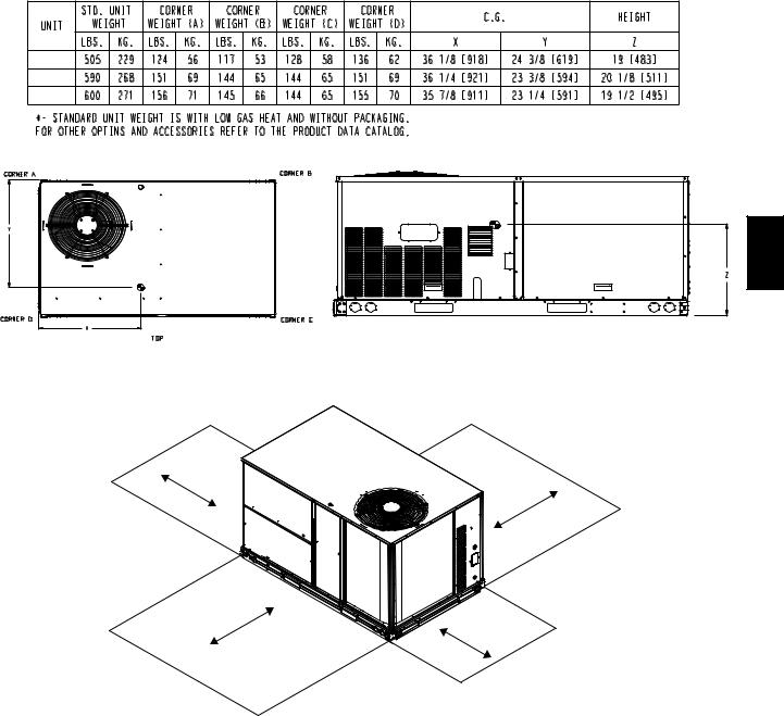
581J-04A
581J-05A
581J-06A
581J
C10379
Fig. 2 - Dimensions 581J04-06
C
D
B
A
C08337
|
|
Fig. 3 - Service Clearance |
|
|
|
|
|
LOC |
DIMENSION |
CONDITION |
|
|
48” (1219 mm) |
Unit disconnect is mounted on panel |
|
A |
18” (457 mm) |
No disconnect, convenience outlet option |
|
18” (457 mm) |
Recommended service clearance |
||
|
|||
|
12” (305 mm) |
Minimum clearance |
|
|
|
|
|
|
42” (1067 mm) |
Surface behind servicer is grounded (e.g., metal, masonry wall) |
|
B |
36” (914 mm) |
Surface behind servicer is electrically non---conductive (e.g., wood, fiberglass) |
|
|
Special |
Check for sources of flue products within 10---ft of unit fresh air intake hood |
|
|
|
|
|
C |
36” (914 mm) |
Side condensate drain is used |
|
18” (457 mm) |
Minimum clearance |
||
|
|||
|
|
|
|
|
48” (1219 mm) |
No flue discharge accessory installed, surface is combustible material |
|
D |
42” (1067 mm) |
Surface behind servicer is grounded (e.g., metal, masonry wall, another unit) |
|
36” (914 mm) |
Surface behind servicer is electrically non---conductive (e.g., wood, fiberglass) |
||
|
|||
|
Special |
Check for adjacent units or building fresh air intakes within 10---ft of this unit’s flue outlet |
|
|
|
|
17
581J
CURBS & WEIGHTS DIMENSIONS - 581J04-06 (cont.)
|
|
|
CONNECTOR |
|
|
|
|
|
|
|
|
B |
|
|
|
|
C |
|
|
D ALT |
|
|
|
|
GAS |
|
|
POWER |
CONTROL |
|
ACCESSORY |
|
|
|
|
|
|
|||||||||||||||||||||||||||||||||||||||||||||||||||||||||||||||||||||||||||||||||||||||||||||||||||||
|
|
|
|
|
|
|
|
|
|
|
|
|
|
|
|
DRAIN |
|
|
|
|
|
|
|
|
|
|
|
|
|
|||||||||||||||||||||||||||||||||||||||||||||||||||||||||||||||||||||||||||||||||||||||||||||||||||||||||||||
|
|
|
PKG. ACCY. |
|
|
|
|
|
|
|
|
|
|
|
|
|
|
|
|
|
|
|
|
|
|
|
|
|
|
|
|
|
HOLE |
|
|
|
|
|
|
|
|
|
|
|
|
|
|
|
|
|
|
|
|
|
|
|
|
|
|
|
|
|
|
|
|
|
|
|
|
|
|
|
|
|
|
|
|
|
POWER |
|
|
|
|
|
|
|||||||||||||||||||||||||||||||||||||||||||||||||||||
|
|
|
|
|
|
|
|
|
|
|
|
|
|
|
|
|
|
|
|
|
|
|
|
|
|
|
|
|
|
|
|
|
|
|
|
|
|
|
|
|
|
|
|
|
|
|
|
|
|
|
|
|
|
|
|
|
|
|
|
|
|
|
|
|
|
|
|
|
|
|
|
|
|
|
|
|
|
|
|
|
|
|
|
|
|
|
|
|
|
|
|
|
|
|
|
|
|
|
|
|
|
|
|
|
|
|
|
|
|
|
|
|
|
|
|
|
|
|
|
|
|
|
|
|
|
|
||||||||||||
CRBTMPWR001A01 |
|
|
|
|
|
|
|
|
|
|
|
|
|
|
|
|
|
|
|
|
|
|
|
|
|
|
|
|
|
|
|
|
|
|
|
|
|
|
|
|
|
|
|
3/4” [19] |
|
|
|
|
|
|
|
|
|
|
|
|
|
|
|
|
|
|
|
|
|
|
|
|
|
|
|
|
|
|
|
|
|
|
|
|
|
|
|
|
|
|
|
|
|
|
|
|
|
|
|
|
|
|
|
|||||||||||||||||||||||||||||||||||||||
|
|
|
1’-911/16” |
|
1’-4” |
|
|
|
|
13/4” |
|
|
|
|
|
NPT |
|
|
3/4” [19] |
1/2” [12.7] |
|
|
|
|
|
1/2” [12.7] |
|
|
|
|
|
|
||||||||||||||||||||||||||||||||||||||||||||||||||||||||||||||||||||||||||||||||||||||||||||||||||||||||||
|
|
|
|
|
|
|
|
|
|
|
|
|
|
|
|
|
|
|
|
|
|
|
|
|
|
|
|
|
|
|
|
|
|
|
|
|
|
|
|
|
|
|
|
|
|
|
|
|
|
|
|
|
||||||||||||||||||||||||||||||||||||||||||||||||||||||||||||||||||||||||||||||||||||||
CRBTMPWR003A01 |
[551] |
|
|
|
|
[406] |
|
[44.5] |
|
|
|
|
1/2” [12.7] |
|
|
NPT |
|
|
|
|
|
|
NPT |
|
|
|
|
|
|
|
|
|
|
|
|
NPT |
|
|
|
|
|
|
||||||||||||||||||||||||||||||||||||||||||||||||||||||||||||||||||||||||||||||||||||||||||||||||
|
|
|
|
|
|
|
|
|
|
|
|
|
|
|
|
|
|
|
|
|
|
|
|
|
|
|
|
|
|
|
|
|
|
|
|
|
|
|
|
|
|
|
|
|
|
NPT |
|
|
|
|
|
|
|
|
|
|
|
|
|
|
|
|
|
|
|
|
|
|
|
|
|
|
|
|
|
|
|
|
|
|
|
|
|
|
|
|
|
|
|
|
|
|
|
|
|
|
|
|
|
|
|
|||||||||||||||||||||||||||||||||||||
|
|
|
|
|
|
|
|
|
|
|
|
|
|
|
|
|
|
|
|
|
|
|
|
|
|
|
|
|
|
|
|
|
|
|
|
|
|
|
|
|
|
|
|
|
|
|
|
|
|
|
|
|
|
|
|
|
|
|
|
|
|
|
|
|
|
|
|
|
|
|
|
|
|
|
|
|
|
|
|
|
|
|
|
|
|
|
|
|
|
|
|
|
|
|
|
|
|
|
|
|
|
|
|
|
|
|
|
|
|
|
|
|
|
|
|
|
|
|
|
|
|
|
|
|
|
|
|
|||||||||||
|
|
|
|
|
|
|
|
|
|
|
|
|
|
|
|
|
|
|
|
|
|
|
|
|
|
|
|
|
|
|
|
|
|
|
|
|
|
|
|
|
|
|
|
|
|
|
|
|
|
|
|
|
|
|
|
|
|
|
|
|
|
|
|
|
|
|
|
|
|
|
|
|
|
|
|
|
|
|
|
|
|
|
|
|
|
|
|
|
|
|
|
|
|
|
|
|
|
|
|
|
|
|
|
|
|
|
|
|
|
|
|
|
|
|
|
|
|
|
|
|
|
|
|
|
|
|
|
|
|
|
|
|
|
|
|
|
|
|
|
|
|
|
|
|
|
|
|
|
|
|
|
|
|
|
|
|
|
|
|
|
|
|
|
|
|
|
|
|
|
|
|
|
|
|
|
|
|
|
|
|
|
|
|
|
|
|
|
|
|
|
|
|
|
|
|
|
|
|
|
|
|
|
|
|
|
|
|
|
|
|
|
|
|
|
|
|
|
|
|
|
|
|
|
|
|
|
|
|
|
|
|
|
|
|
|
|
|
|
|
|
|
|
|
|
|
|
|
|
|
|
|
|
|
|
|
|
|
|
|
|
|
|
|
|
|
|
|
|
|
|
|
|
|
|
|
|
|
|
|
|
|
|
|
|
|
|
|
|
|
|
|
|
|
|
|
|
|
|
|
|
|
|
|
|
|
|
|
|
|
|
|
|
|
|
|
|
|
|
|
|
|
|
|
|
|
|
|
|
|
|
|
|
|
|
|
|
|
|
|
|
|
|
|
|
|
|
|
|
|
|
|
|
|
|
|
|
|
|
|
|
|
|
|
|
|
|
|
|
|
|
|
|
|
|
|
|
|
|
|
|
|
|
|
|
|
|
|
|
|
|
|
|
|
|
|
|
|
|
|
|
|
|
|
|
|
|
|
|
|
|
|
|
|
|
|
|
|
|
|
|
|
|
|
|
|
|
|
|
|
|
|
|
|
|
|
|
|
|
|
|
|
|
|
|
|
|
|
|
|
|
|
|
|
|
|
|
|
|
|
|
|
|
|
|
|
|
|
|
|
|
|
|
|
|
|
|
|
|
|
|
|
|
|
|
|
|
|
|
|
|
|
|
|
|
|
|
|
|
|
|
|
|
|
|
|
|
|
|
|
|
|
|
|
|
|
|
|
|
|
|
|
|
|
|
|
|
|
|
|
|
|
|
|
|
|
|
|
|
|
|
|
|
|
|
|
|
|
|
|
|
|
|
|
|
|
|
|
|
|
|
|
|
|
|
|
|
|
|
|
|
|
|
|
|
|
|
|
|
|
|
|
|
|
|
|
|
|
|
|
|
|
|
|
|
|
|
|
|
|
|
|
|
|
|
|
|
|
|
|
|
|
|
|
|
|
|
|
|
|
|
|
|
|
|
|
|
|
|
|
|
|
|
|
|
|
|
|
|
|
|
|
|
|
|
|
|
|
|
|
|
|
|
|
|
|
|
|
|
|
|
|
|
|
|
|
|
|
|
|
|
|
|
|
|
|
|
|
|
|
|
|
|
|
|
|
|
|
|
|
|
|
|
|
|
|
|
|
|
|
|
|
|
|
|
|
|
|
|
|
|
|
|
|
|
|
|
|
|
|
|
|
|
|
|
|
|
|
|
|
|
|
|
|
|
|
|
|
|
|
|
|
|
|
|
|
|
|
|
|
|
|
|
|
|
|
|
|
|
|
|
|
|
|
|
|
|
|
|
|
|
|
|
|
|
|
|
|
|
|
|
|
|
|
|
|
|
|
|
|
|
|
|
|
|
|
|
|
|
|
|
|
|
|
|
|
|
|
|
|
|
|
|
|
|
|
|
|
|
|
|
|
|
|
|
|
|
|
|
|
|
|
|
|
|
|
|
|
|
|
|
|
|
|
|
|
|
|
|
|
|
|
|
|
|
|
|
|
|
|
|
|
|
|
|
|
|
|
|
|
|
|
|
|
|
|
|
|
|
|
|
|
|
|
|
|
|
|
|
|
|
|
|
|
|
|
|
|
|
|
|
|
|
|
|
|
|
|
|
|
|
|
|
|
|
|
|
|
|
|
|
|
|
|
|
|
|
|
|
|
|
|
|
|
|
|
|
|
|
|
|
|
|
|
|
|
|
|
|
|
|
|
|
|
|
|
|
|
|
|
|
|
|
|
|
|
|
|
|
|
|
|
|
|
|
|
|
|
|
|
|
|
|
|
|
|
|
|
|
|
|
|
|
|
|
|
|
|
|
|
|
|
|
|
|
|
|
|
|
|
|
|
|
|
|
|
|
|
|
|
|
|
|
|
|
|
|
|
|
|
|
|
|
|
|
|
|
|
|
|
|
|
|
|
|
|
|
|
|
|
|
|
|
|
|
|
|
|
|
|
|
|
|
|
|
|
|
|
|
|
|
|
|
|
|
|
|
|
|
|
|
|
|
|
|
|
|
|
|
|
|
|
|
|
|
|
|
|
|
|
|
|
|
|
|
|
|
|
|
|
|
|
|
|
|
|
|
|
|
|
|
|
|
|
|
|
|
|
|
|
|
|
|
|
|
|
|
|
|
|
|
|
|
|
|
|
|
|
|
|
|
|
|
|
|
|
|
|
|
|
|
|
|
|
|
|
|
|
|
|
|
|
|
|
|
|
|
|
|
|
|
|
|
|
|
|
|
|
|
|
|
|
|
|
|
|
|
|
|
|
|
|
|
|
|
|
|
|
|
|
|
|
|
|
|
|
|
|
|
|
|
|
|
|
|
|
|
|
|
|
|
|
|
|
|
|
|
|
|
|
|
|
|
|
|
|
|
|
|
|
|
|
|
|
|
|
|
|
|
|
|
|
|
|
|
|
|
|
|
|
|
|
|
|
|
|
|
|
|
|
|
|
|
|
|
|
|
|
|
|
|
|
|
|
|
|
|
|
|
|
|
|
|
|
|
|
|
|
|
|
|
|
|
|
|
|
|
|
|
|
|
|
|
|
|
|
|
|
|
|
|
|
|
|
|
|
|
|
|
|
|
|
|
|
|
|
|
|
|
|
|
|
|
|
|
|
|
|
|
|
|
|
|
|
|
|
|
|
|
|
|
|
|
|
|
|
|
|
|
|
|
|
|
|
|
|
|
|
|
|
|
|
|
|
|
|
|
|
|
|
|
|
|
|
|
|
|
|
|
|
|
|
|
|
|
|
|
|
|
|
|
|
|
|
|
|
|
|
|
|
|
|
|
|
|
|
|
|
|
|
|
|
|
|
|
|
|
|
|
|
|
|
|
|
|
|
|
|
|
|
|
|
|
|
|
|
|
|
|
|
|
|
|
|
|
|
|
|
|
|
|
|
|
|
|
|
|
|
|
|
|
|
|
|
|
|
|
|
|
|
|
|
|
|
|
|
|
|
|
|
|
|
|
|
|
|
|
|
|
|
|
|
|
|
|
|
|
|
|
|
|
|
|
|
|
|
|
|
|
|
|
|
|
|
|
|
|
|
|
|
|
|
|
|
|
|
|
|
|
|
|
|
|
|
|
|
|
|
|
|
|
|
|
|
|
|
|
|
|
|
|
|
|
|
|
|
|
|
|
|
|
|
|
|
|
|
|
|
|
|
|
|
|
|
|
|
|
|
|
|
|
|
|
|
|
|
|
|
|
|
|
|
|
|
|
|
|
|
|
|
|
|
|
|
|
|
|
|
|
|
|
|
|
|
|
|
|
|
|
|
|
|
|
|
|
|
|
|
|
|
|
|
|
|
|
|
|
|
|
|
|
|
|
|
|
|
|
|
|
|
|
|
|
|
|
|
|
|
|
|
|
|
|
|
|
|
|
|
|
|
|
|
|
|
|
|
|
|
|
|
|
|
|
|
|
|
|
|
|
|
|
|
|
|
|
|
|
|
|
|
|
|
|
|
|
|
|
|
|
|
|
|
|
|
|
|
|
|
|
|
|
|
|
|
|
|
|
|
|
|
|
|
|
|
|
|
|
|
|
|
|
|
|
|
|
|
|
|
|
|
|
|
|
|
|
|
|
|
|
|
|
|
|
|
|
|
|
|
|
|
|
|
|
|
|
|
|
|
|
|
|
|
|
|
|
|
|
|
|
|
|
|
|
|
|
|
|
|
|
|
|
|
|
|
|
|
|
|
|
|
|
|
|
|
|
|
|
|
|
|
|
|
|
|
|
|
|
|
|
|
|
|
|
|
|
|
|
|
|
|
|
|
|
|
|
|
|
|
|
|
|
|
|
|
|
|
|
|
|
|
|
|
|
|
|
|
|
|
|
|
|
|
|
|
|
|
|
|
|
|
|
|
|
|
|
|
|
|
|
|
|
|
|
|
|
|
|
|
|
|
|
|
|
|
|
|
|
|
|
|
|
|
|
|
|
|
|
|
|
|
|
|
|
|
|
|
|
|
|
|
|
|
|
|
|
|
|
|
|
|
|
|
|
|
|
|
|
|
|
|
|
|
|
|
|
|
|
|
|
|
|
|
|
|
|
|
|
|
|
|
|
|
|
|
|
|
|
|
|
|
|
|
|
|
|
|
|
|
|
|
|
|
|
|
|
|
|
|
|
|
|
|
|
|
|
|
|
|
|
|
|
|
|
|
|
|
|
|
|
|
|
|
|
|
|
|
|
|
|
|
|
|
|
|
|
|
|
|
|
|
|
|
|
|
|
|
|
|
|
|
|
|
|
|
|
|
|
|
|
|
|
|
|
|
|
|
|
|
|
|
|
|
|
|
|
|
|
|
|
|
|
|
|
|
|
|
|
|
|
|
|
|
|
|
|
|
|
|
|
|
|
|
|
|
|
|
|
|
|
|
|
|
|
|
|
|
|
|
|
|
|
|
|
|
|
|
|
|
|
|
|
|
|
|
|
|
|
|
|
|
|
|
|
|
|
|
|
|
|
|
|
|
|
|
|
|
|
|
|
|
|
|
|
|
|
|
|
|
|
|
|
|
|
|
|
|
|
|
|
|
|
|
|
|
|
|
|
|
|
|
|
|
|
|
|
|
|
|
|
|
|
|
|
|
|
|
|
|
|
|
|
|
|
|
|
|
|
|
|
|
|
|
|
|
|
|
|
|
|
|
|
|
|
|
|
|
|
|
|
|
|
|
|
|
|
|
|
|
|
|
|
|
|
|
|
|
|
|
|
|
|
|
|
|
|
|
|
|
|
|
|
|
|
|
|
|
|
|
|
|
|
|
|
|
|
|
|
|
|
|
|
|
|
|
|
|
|
|
|
|
|
|
|
|
|
|
|
|
|
|
|
|
|
|
|
|
|
|
|
|
|
|
|
|
|
|
|
|
|
|
|
|
|
|
|
|
|
|
|
|
|
|
|
|
|
|
|
|
|
|
|
|
|
|
|
|
|
|
|
|
|
|
|
|
|
|
|
|
|
|
|
|
|
|
|
|
|
|
|
|
|
|
|
|
|
|
|
|
|
|
|
|
|
|
|
|
|
|
|
|
|
|
|
|
|
|
|
|
|
|
|
|
|
|
|
|
|
|
|
|
|
|
|
|
|
|
|
|
|
|
|
|
|
|
|
|
|
|
|
|
|
|
|
|
|
|
|
|
|
|
|
|
|
|
|
|
|
|
|
|
|
|
|
|
|
|
|
|
|
|
|
|
|
|
|
|
|
|
|
|
|
|
|
|
|
|
|
|
|
|
|
|
|
|
|
|
|
|
|
|
|
|
|
|
|
|
|
|
|
|
|
|
|
|
|
|
|
|
|
|
|
|
|
|
|
|
|
|
|
|
|
|
|
|
|
|
|
|
|
|
|
|
|
|
|
|
|
|
|
|
|
|
|
|
|
|
|
|
|
|
|
|
|
|
|
|
|
|
|
|
|
|
|
|
|
|
|
|
|
|
|
|
|
|
|
|
|
|
|
|
|
|
|
|
|
|
|
|
|
|
|
|
|
|
|
|
|
|
|
|
|
|
|
|
|
|
|
|
|
|
|
|
|
|
|
|
|
|
|
|
|
|
|
|
|
|
|
|
|
|
|
|
|
|
|
|
|
|
|
|
|
|
|
|
|
|
|
|
|
|
|
|
|
|
|
|
|
|
|
|
|
|
|
|
|
|
|
|
|
|
|
|
|
|
|
|
|
|
|
|
|
|
|
|
|
|
|
|
|
|
|
|
|
|
|
|
|
|
|
|
|
|
|
|
|
|
|
|
|
|
|
|
|
|
|
|
|
|
|
|
|
|
|
|
|
|
|
|
|
|
|
|
|
|
|
|
|
|
|
|
|
|
|
|
|
|
|
|
|
|
|
|
|
|
|
|
|
|
|
|
|
|
|
|
|
|
|
|
|
|
|
|
|
|
|
|
|
|
|
|
|
|
|
|
|
|
|
|
|
|
|
|
|
|
|
|
|
|
|
|
|
|
|
|
|
|
|
|
|
|
|
|
|
|
|
|
|
|
|
|
|
|
|
|
|
|
|
|
|
|
|
|
|
|
|
|
|
|
|
|
|
|
|
|
|
|
|
|
|
|
|
|
|
|
|
|
|
|
|
|
|
|
|
|
|
|
|
|
|
|
|
|
|
|
|
|
|
|
|
|
|
|
|
|
|
|
|
|
|
|
|
|
|
|
|
|
|
|
|
|
|
|
|
|
|
|
|
|
|
|
|
|
|
|
|
|
|
|
|
|
|
|
|
|
|
|
|
|
|
|
|
|
|
|
|
|
|
|
|
|
|
|
|
|
|
|
|
|
|
|
|
|
|
|
|
|
|
|
|
|
|
|
|
|
|
|
|
|
|
|
|
|
|
|
|
|
|
|
|
|
|
|
|
|
|
|
|
|
|
|
|
|
|
|
|
|
|
|
|
|
|
|
|
|
|
|
|
|
|
|
|
|
|
|
|
|
|
|
|
|
|
|
|
|
|
|
|
|
|
|
|
|
|
|
|
|
|
|
|
|
|
|
|
|
|
|
|
|
|
|
|
|
|
|
|
|
|
|
|
|
|
|
|
|
|
|
|
|
|
|
|
|
|
|
|
|
|
|
|
|
|
|
|
|
|
|
|
|
|
|
|
|
|
|
|
|
|
|
|
|
|
|
|
|
|
|
|
|
|
|
|
|
|
|
|
|
|
|
|
|
|
|
|
|
|
|
|
|
|
|
|
|
|
|
|
|
|
|
|
|
|
|
|
|
|
|
|
|
|
|
|
|
|
|
|
|
|
|
|
|
|
|
|
|
|
|
|
|
|
|
|
|
|
|
|
|
|
|
|
|
|
|
|
|
|
|
|
|
|
|
|
|
|
|
|
|
|
|
|
|
|
|
|
|
|
|
|
|
|
|
|
|
|
|
|
|
|
|
|
|
|
|
|
|
|
|
|
|
|
|
|
|
|
|
|
|
|
|
|
|
|
|
|
|
|
|
|
|
|
|
|
|
|
|
|
|
|
|
|
|
|
|
|
|
|
|
|
|
|
|
|
|
|
|
|
|
|
|
|
|
|
|
|
|
|
|
|
|
|
|
|
|
|
|
|
|
ROOFCURB |
A |
UNIT SIZE |
|
ACCESSORY |
|||
|
|
||
|
|
|
|
CRRFCURB001A01 |
1’-2” |
|
|
[356] |
581J*04-06 |
||
|
|
||
CRRFCURB002A01 |
2’-0” |
||
|
|||
[610] |
|
||
|
|
||
|
|
|
NOTES:
1.Roof curb accessory is shipped disassembled.
2.Insulated panels.
3. Dimensions in [ ] are in millimeters.
4.Roof curb: galvanized steel.
5.Attach ductwork to curb (flanges of duct rest on curb).
6.Service clearance: 4 ft on each side.
7.

 Direction of airflow.
8.Connector package CRBTMPWR001A01 is for thru-the-curb type gas.
CRBTMPWR003A01 is for thru-the-base type gas connections.
Typical Corner Fastening Device
C10423
Fig. 4 - Roof Curb Details
18
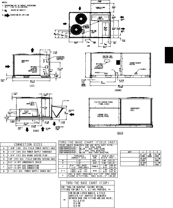
CURBS & WEIGHTS DIMENSIONS - 581J07-09
581J
581J
581J
581J
Fig. 5 - Dimensions 581J07-09
581J-07A |
|
581J-08D |
36 3/8 |
(924) |
|
581J-09D |
36 3/8 |
(924) |
C10425
19
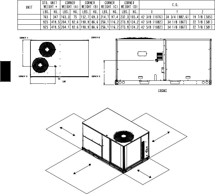
CURBS & WEIGHTS DIMENSIONS - 581J07-09 (cont.)
581J-07A |
581J-08D |
581J-09D |
581J
C10381
Fig. 6 - Dimensions 581J07-09
C
D
B
A
C08337
|
|
Fig. 7 - Service Clearance |
|
|
|
|
|
LOC |
DIMENSION |
CONDITION |
|
|
48” (1219 mm) |
Unit disconnect is mounted on panel |
|
A |
18” (457 mm) |
No disconnect, convenience outlet option |
|
18” (457 mm) |
Recommended service clearance |
||
|
|||
|
12” (305 mm) |
Minimum clearance |
|
|
|
|
|
|
42” (1067 mm) |
Surface behind servicer is grounded (e.g., metal, masonry wall) |
|
B |
36” (914 mm) |
Surface behind servicer is electrically non---conductive (e.g., wood, fiberglass) |
|
|
Special |
Check for sources of flue products within 10---ft of unit fresh air intake hood |
|
|
|
|
|
C |
36” (914 mm) |
Side condensate drain is used |
|
18” (457 mm) |
Minimum clearance |
||
|
|||
|
|
|
|
|
48” (1219 mm) |
No flue discharge accessory installed, surface is combustible material |
|
D |
42” (1067 mm) |
Surface behind servicer is grounded (e.g., metal, masonry wall, another unit) |
|
36” (914 mm) |
Surface behind servicer is electrically non---conductive (e.g., wood, fiberglass) |
||
|
|||
|
Special |
Check for adjacent units or building fresh air intakes within 10---ft of this unit’s flue outlet |
|
|
|
|
20
Loading...