


Cover Stitch Machine Operation Manual
Manual de instrucciones de la máquina de puntada de recubierto
CONTENTS: ENGLISH |
|
I. Names of parts and their functions ............. |
3 |
II. Preparation before threading ..................... |
8 |
III. Threading .................................................. |
9 |
IV. Types of stitches ..................................... |
11 |
Tri-cover stitch ............................................. |
11 |
Two needle three threads cover stitch ........ |
12 |
Chain stitch sewing ..................................... |
14 |
V. Sewing ..................................................... |
15 |
VI. Maintenance ........................................... |
19 |
VII. Machine specifications .......................... |
19 |
ENGLISH
INDICE: ESPAÑOL |
|
I. Nombres de las partes y sus funciones .... |
21 |
II. Preparación antes del enhebrado ............ |
26 |
III. Enhebrado .............................................. |
27 |
IV. Tipos de puntadas ................................... |
29 |
Puntada de recubierto triple ....................... |
29 |
Puntada de recubierto de |
|
dos agujas con tres hilos ................. |
30 |
Costura de puntada de cadena .................. |
32 |
ESPAÑOL
V. Costura .................................................... |
33 |
VI. Mantenimiento ........................................ |
37 |
VII. Especificaciones de la máquina ............ |
37 |
"IMPORTANT SAFETY INSTRUCTIONS"
When using the sewing machine, basic safety precautions should always be followed, including the following.
"Read all instructions before using." DANGER – To reduce the risk of electric shock.
1.The sewing machine should never be left unattended when plugged in. Always unplug this sewing machine from the electrical outlet immediately after using and before cleaning.
2.Always unplug before relamping. Replace bulb with same type rated 15 watts.
WARNING – To reduce the risk of burns, fire, electric shock, or injury to persons.
1.Do not allow to be used as a toy. Close attention is necessary when the sewing machine is used by or near children.
2.Use this sewing machine only for its intended use as described in this manual. Use only accessories recommended by the manufacturer as contained in this manual.
3.Never operate this sewing machine if it has a damaged cord or plug, if it is not working properly, if it has been dropped or damaged, or dropped into water. Return the sewing machine to the nearest authorized dealer or service center for examination, repair, electrical or mechanical adjustment.
4.Never operate the sewing machine with any air openings blocked. Keep ventilation openings of the sewing machine and foot controller free from the accumulation of lint, dust, and loose cloth.
5.Never drop or insert any object into any openings.
6.Do not use outdoors.
7.Do not operate where aerosol (spray) products are being used or where oxygen is being administered.
8.To disconnect, turn the main switch to the symbol “O” position which represents off, then remove plug from outlet.
9.Do not unplug by pulling on cord. To unplug, grasp the plug, not the cord.
10.Keep fingers away from all moving parts. Special care is required around the sewing machine needle.
11.Always use the proper needle plate. The wrong plate can cause the needle to break.
12.Do not use bent needles.
13.Do not pull or push fabric while stitching. It may deflect the needle causing it to break.
14.Switch the sewing machine to the symbol “O” position when making any adjustments in the needle area, such as threading needle, changing needle, or changing presser foot, and the like.
15.Always unplug the sewing machine from the electrical outlet when removing covers, lubricating, or when making any other user servicing adjustments mentioned in the instruction manual.
16.This sewing machine is not intended for use by young children or infirm persons without supervision.
17.Young children should be supervised to ensure that they do not play with this sewing machine.
CAUTION – This appliance has a polarized plug (one blade wider than the other) to reduce the risk of electric shock, this plug is intended to fit in a polarized outlet only one way.
If the plug does not fit fully in the outlet, reverse the plug.
If it still does not fit. Contact a qualified electrician to install the proper outlet. Do not modify the plug in any way.
"SAVE THESE INSTRUCTIONS"
"This sewing machine is intended for household."
•When leaving this sewing machine unattended, the main switch of the machine must be switched off or the plug must be removed from the socketoutlet.
•When servicing the sewing machine, or when removing covers or changing lamps, the machine or the electrical set must be disconnected from the supply by removing the plug from the socket-outlet.
ENGLISH
FOR USERS IN THE UK, EIRE, MALTA AND CYPRUS ONLY.
If your sewing machine is fitted with a 3 pin non rewireable BS plug then please read the following.
IMPORTANT
If the available socket outlet is not suitable for the plug supplied with this equipment, it should be cut off and an appropriate three pin plug fitted. With alternative plugs an approved fuse must be fitted in the plug.
NOTE: The plug severed from the mains lead must be destroyed as a plug with bared flexible cords is hazardous if engaged in a live socket outlet. In the event of replacing the plug fuse, use a fuse approved by ASTA to BS 1362, i.e. carrying the ASA mark, rating as marked on plug.
Always replace the fuse cover, never use plugs with the fuse cover omitted.
WARNING: DO NOT CONNECT EITHER WIRE TO THE EARTH TERMINAL WHICH IS MARKED WITH THE LETTER ‘E’, BY THE EARTH SYMBOL  OR COLOURED GREEN OR GREEN AND YELLOW.
The wires in this mains lead are coloured in accordance with the following code:
Blue |
Neutral |
Brown |
Live |
As the colours of the wiring in the mains lead of this appliance may not correspond with the coloured markings identifying the terminals in your plug, proceed as follows.
The wire which is coloured blue must be connected to the terminal which is marked with the letter ‘N’ or coloured black or blue.
The wire which is coloured brown must be connected to the terminal which is marked with the letter ‘L’ or coloured red or brown.
1

CONGRATULATIONS ON
CHOOSING THIS COMPACT COVER STITCH MACHINE
Your machine is a high quality, easy-to-use product. To fully enjoy all the features, we suggest that you study this booklet.
If you need more information regarding the use of your machine, your nearest authorized dealer is always happy to be of service.
Enjoy yourself!
CAUTION!
WHEN THREADING, REPLACING NEEDLE OR LIGHT BULB, BE SURE TO TURN OFF THE MAIN POWER SWITCH OF THE MACHINE.
WHEN THE MACHINE IS NOT IN USE, IT IS RECOMMENDED THAT THE ELECTRIC SUPPLY PLUG IS DISCONNECTED FROM THE WALL SOCKET TO AVOID ANY POSSIBLE HAZARDS.
Notes on the motor
•The normal operating speed of this sewing machine is 1,000 stitches per minute, which is quite fast compared to the normal operating speed of 300 to 800 stitches per minute for the ordinary foot-operated sewing machine.
•The bearings in the motor are made of a special sintered, oil-impregnated alloy mounted in oil-soaked felt to withstand long hours of continuous operation.
•Continuous operation of the sewing machine can cause heat to build in the motor area, but not enough to adversely affect its performance.
It is important to keep fabric and paper away from the ventilating holes on the back and sides of the machine so air can get to these holes.
•When the motor is running, sparks can be seen through the ventilating hole in the motor bracket on the side opposite the hand wheel. These sparks are produced by the carbon brushes and the commutator, and are part of the machines normal operation.
CAUTION
WHEN THREADING THE MACHINE, REPLACING A NEEDLE, OR WHEN THE MACHINE IS NOT IN USE, WE RECOMMEND DISCONNECTING THE ELECTRIC SUPPLY PLUG TO AVOID ANY POSSIBLE HAZARDS.
2

I. Names of parts and their functions
D E
1 3 |
G |
|
H I L
2 J K
J K
4
F
5
6
8
7
9
C
0 A
B
P  M O
M O
N
1 Thread tree
2 Thread plate
3 Presser foot pressure adjustment screw
4 Spool pin
5 Spool cushion
6 Spool support
7 Thread take-up cover
8 Material plate cover
9 Needles
0 Differential feed raito adjustment dial
A Stitch length adjustment dial
B Presser foot
C Front cover
D Hand wheel
E Main power switch and light switch
F Presser foot lifting lever
G Spool stand
H Left needle thread tension dial
I Center needle thread tension dial
J Right needle thread tension dial
K Looper thread tension dial
L Thread guide
M Looper
N Looper release lever
O Lopper thread take up
P Foot controller:
J01780051 (110/120V Area)
XA6406051 (220/240V Area)
XA6408051 (U.K.)
XA6410051 (Australia, New Zealand)
XA6420051 (Germany)
Accessories included
1 |
3 |
7 |
1 Soft cover |
X77871001 |
|
|
|
2 Accessory bag |
122991002 |
|
4 |
8 |
3 Tweezers |
X75902001 |
|
4 Thread net (4) |
X75904000 |
||
|
|
|||
|
|
|
||
|
|
|
5 Thread spool cap (4) |
X77260000 |
|
5 |
9 |
6 Spool mat (4) |
XB1218000 |
|
|
7 Cleaning brush |
X75906001 |
|
2 |
|
|
||
|
|
8 Hexagonal wrench |
XB0393001 |
|
|
|
|
||
|
6 |
|
9 Needle set: SCHMETZ 130/705H |
|
|
|
(90/#14): 3pcs. |
XB1216001 |
|
|
|
|
||
0
0 Special presser foot (LC1) XB1265001 The special presser foot is used when an optional attachment is used.
ENGLISH
3
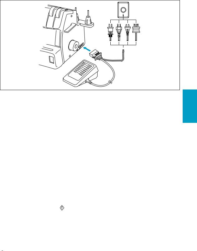
Powering the machine
1
 2
2
NOTE: (For U.S.A. only)
This foot controller can be used for sewing machine model 2340CV.
Preparation
•Insert the three-pin plug into the socket on the bottom right side of the machine. Insert the power supply plug into a power outlet.
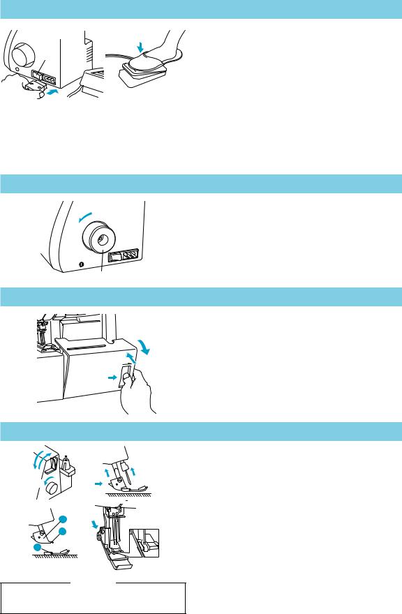
Main Power and Sewing Light Switch
This switch turns the power and sewing light on or off. To turn on push toward “ – ” mark. To turn off push toward “ ” mark.
1Main Power and Sewing Light Switch
Operation
When the pedal is pressed lightly, the machine runs at a low speed. As the pedal is pressed further, the machine will increase speed. When the pedal is released, the machine stops.
2Foot Controller: Model N
Turning direction of motor
•The motor and hand wheel of this machine turn in a counterclockwise direction (direction of arrow). This is the same direction as an ordinary home sewing machine.
1Hand wheel
1
Opening and closing the front cover
It is necessary to open the front cover when threading this machine.
• Open the front cover by sliding it to the right and guiding the top toward you.
NOTE:
For your safety, make sure that the front cover is closed when operating the machine.
How to attach and remove the presser foot
41 |
1 |
2 |
|
3 |
|||
2 |
|
||
|
|
A
B
C  4
4
CAUTION
Always be sure to turn off the power before carrying out this operation.
• Turn off the main power switch or disconnect the electric supply plug.
(1)Raise the presser foot lever. 1
(2)Set the needle to its highest position by turning the hand wheel 2 counter clockwise.
(3)Push the button on the presser foot holder and the standard foot will be released. 3 4
(4)Raise the presser foot farther by pushing the presser foot lever upward. Then remove the presser foot and store it in a safe location.
(5)Again, raise the presser foot farther by pushing the presser foot lever upward. Then place a presser foot just under the presser foot holder A so that the groove in the bottom of the presser foot holder B is aligned and catches the bar on the top of the foot C. Then lower the presser foot lever to attach the foot.
4
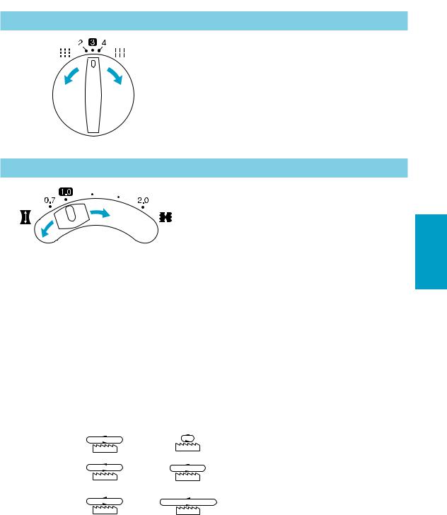
Stitch length
To change the stitch length,
(1)Locate the stitch length adjustment dial on the left side of the machine.
(2)Turn the stitch length adjustment dial forward to lengthen the stitch to a maximum of 4 mm (5/32 inch). Turn the stitch length adjustment dial backwards to shorten the stitch length to a minimum of 2 mm (5/64 inch).
(3)The normal stitch length setting is 3 mm to 4 mm (1/8 to 5/32 inch)
Instructions for the differential feed mechanism
|
|
This machine is equipped with two sets of feed dogs |
|||
|
|
under the presser foot to move the fabric through the |
|||
|
(4) |
machine. The differential feed controls the movement of |
|||
|
both the front and the rear feed dogs. When set at 1, the |
||||
|
|
feed dogs are moving at the same speed (ratio of 1). |
|||
(3) |
|
When the differential feed ratio is set at less than 1, the |
|||
|
front feed dogs move slower than the rear feed dogs, |
||||
|
|
||||
|
|
stretching the fabric as it is sewn. This is effective on |
|||
|
|
lightweight fabric that may pucker. When the differential |
|||
|
|
feed ratio is set at greater than 1, the front feed dogs |
|||
|
|
move faster than the back feed dogs, gathering the fabric |
|||
|
|
as it is sewn. This function assists in removing the rippling |
|||
|
|
when serging stretch fabrics. |
|
||
|
|
• To adjust the differential feed. |
|
||
|
|
(1)Locate the differential feed adjustment lever on the left |
|||
|
|
side of the machine. |
|
||
|
|
(2)The normal setting is 1.0 on the differential feed |
|||
|
|
adjustment lever. |
|
||
|
|
(3)To set less than 1.0, move the lever back. |
|||
|
|
(4)To set greater than 1.0, move the lever forward. |
|||
|
|
|
|
|
|
Feed ratio |
Main feed (rear) |
Differential feed (front) |
Effect |
|
Application |
0.7 – 1.0 |
|
|
Material is pulled |
|
Prevents thin mate- |
|
|
tight. |
|
rials from puckering |
|
|
|
|
|
||
|
|
|
|
|
|
1.0 |
|
|
Without differential |
|
Normal sewing |
|
|
feed. |
|
|
|
|
|
|
|
|
|
|
|
|
|
|
|
1.0 – 2.0 |
|
|
Material is gath- |
|
Prevents stretch ma- |
|
|
ered or pushed |
|
terials from stretch- |
|
|
|
|
together. |
|
ing or puckering |
|
|
|
|
|
|
ENGLISH
5
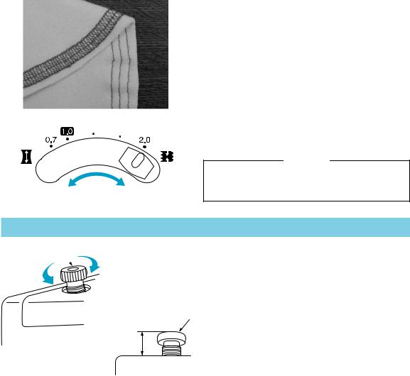
• An example where adjustment is required
When stretch material is sewn without using the differential feed, the material will be wavy.
To make the material more smooth, adjust the feed ratio from 1.0 toward 2.0.
(The feed ratio required depends on the elasticity of the material.)
The more elastic the material, the further toward 2.0 the differential feed ratio should be set. Test sew with a scrap of the fabric to find the correct adjustment.
CAUTION
When sewing thick non-stretchable material such as denim, do not use the differential feed as it may damage the fabric.
Presser foot pressure
1
2  3
3
5 10mm (3/8 inch)
•The pressure of the presser foot can be adjusted by turning the pressure adjustment screw at the top left of this machine. Since this machine has already been adjusted to a pressure suitable for light to medium fabrics, no further adjustment is necessary except
when sewing on very heavy or very light materials.
4Usually, when sewing on very light materials, the presser foot pressure should be loosened. When
sewing very heavy materials, the presser foot pressure should be tightened.
1Pressure adjustment screw
2Less pressure
3More pressure
4Pressure adjustment screw
5(Standard height for medium material)
6
Needle
5
3
1
2
4
6 7 8
NOTE:
When front needles are inserted correctly you can see the top of the needle in the window (5) above each needle position.
CAUTION
Always be sure to turn off the power before carrying out this operation.
CAUTION
Do not drop the needle and needle set screw in the machine, otherwise it may be damaged.
This machine uses a standard home sewing machine needle.
The recommended needle is SCHMETZ 130/705H (90/#14).
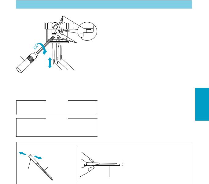
To remove the needle
(1)Turn the main power switch to the OFF position. (2)Turn the hand wheel counter-clockwise by hand until
the needle is at its highest position.
(3)Loosen the needle set screw with hexagonal wrench and remove the needle.
To insert the needle
(1)Turn the main power switch to the OFF position. (2)Turn the hand wheel until the needle bar is at its
highest position.
(3)Hold the needle with its flat side away from you and insert it up as far as it will go.
(4)Tighten the needle set screw securely with the hexagonal wrench.
1Needle set screw
2Tighten
3Loosen
4Hexagonal wrench
5Window
6Left needle
7Center needle
8Right needle
Needle description |
How to check the needle |
1 |
2 |
1Back |
|
||
|
|
|
|
4 |
2Front |
|
3Flat side |
|
|
3 |
4Groove |
5
5Flat surface
66Place the needle on its flat side and check to see if the space is parallel.
NOTE:
Countermeasures for material breakage.
It can reduce the occurrence of material breakage by using SCHIMETZ 130/705H SUK (90/#14) BALL POINT.
ENGLISH
7
II. Preparation before threading
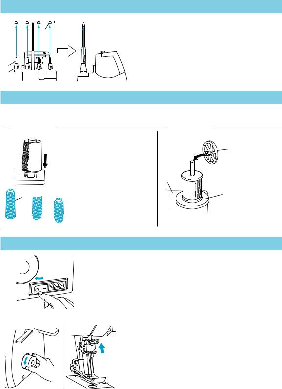
Thread tree
4 |
Raise the telescoping thread tree to its highest position. |
|
1 |
Make sure that the thread holders are in alignment above |
|
the spool pins as illustrated left. |
||
|
||
|
1Thread holder on thread tree |
|
|
2Spool pin |
|
|
3Spool cushion |
|
2 |
4Correct position |
|
|
||
3 |
|
Thread spool
The procedure for placing the spool of thread on the spool pin differs according to the shape of the spool.
Type A
1
 2
2
3 
|
Type B |
|
If you are sewing with loosely |
3 |
|
spun nylon thread, we recom- |
||
mend that you cover the spool |
|
|
with the net supplied to prevent |
|
|
the thread from slipping off the |
|
|
spool. |
1 |
|
Adapt the net to the shape of the |
|
|
spool. |
2 |
|
1Spool support |
||
|
||
2Spool cushion |
|
|
3Net |
|
1Spool support
2Spool mat
3Spool cap
Needle position
(1)
(2)
(1)Turn off the main power switch for safety.
(2)Set the needle bar in its highest position by turning the handwheel toward you.
Turn the handwheel to find the easiest position for threading.
8
III. Threading
Needle threading
333
 333
333
F |
6 |
|
5 |
G |
|
|
4 |
|
444 |
|
|
•Pass each thread from 333 to 444 as shown in this illustration.
•Pass the thread through the proper thread guide.
•Slide and hold the thread tension release button to the right, then pass the thread through the tension disc which is in the channel next to the tension adjustment dial. Release the button.
FTension disk
GThread tension release button
1 |
1 |
|
1 |
|
2 |
2 |
2 |
3 3 3
A |
D |
|
|
|
|
|
|
|
B C |
6664 4 4 |
|
|
777 |
5 |
5 5 |
|
|
|
|
888
E

999
CAUTION
Always be sure to turn off the power before carrying out the following operation.
(1) Follow the procedure described below to thread the needle.
Threading the left needle
•Run the thread in the sequence illustrated, following the yellow color and the numbers next to each threading point. (1-9)
Threading the center needle
•Run the thread in the sequence illustrated, following the pink color and the numbers next to each threading point. (1-9)
Threading the right needle
•Run the thread in the sequence illustrated, following the green color and the numbers next to each threading point. (1-9)
CAUTION
When needle threading, always thread in this order: Left needle, center needle and then right needle.
ATo left needle
BTo center needle
CTo right needle DBranching plate
EPull about 6 cm (about 2-1/2 inches) of thread through the eye of the needle.
999Front to back
ENGLISH
9
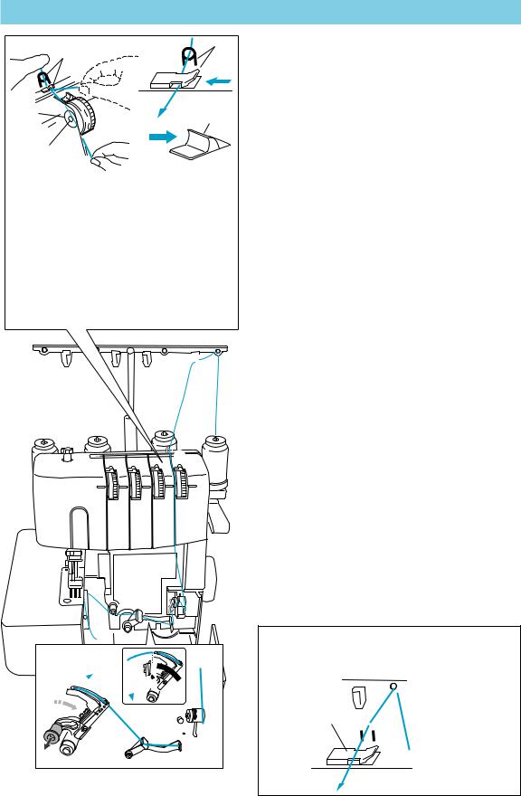
Looper threading
 3
3
A |
6 |
5 |
|
|
4 |
4
3 |
|
|
CAUTION |
|
|
|
|
||
|
Always be sure to turn off the power before |
|||
|
|
|||
|
|
carrying out the following operation. |
||
|
|
|
|
|
|
|
|
|
|
B
•Pass each thread from 3 to 4 as shown in this illustration.
•Pass the thread through the proper thread guide.
•Slide and hold the thread tension release button to the right, then pass the thread through the tension disc which is in the channel next to the tension adjustment dial. Release the button.
ATension disk
BThread tension release button
 1 2
1 2


 3
3
4
5
(1)Follow the procedure described below to thread the looper.
1Open the front cover by sliding to the right and guiding the top toward you.
2Run the thread in the sequence illustrated, following the blue color and the numbers next to each threading point. (1-0)
3After running the thread to 0, pull the release lever A, and then run the thread through B and C.
4With about 10 cm (4 inch) of thread pulled through the eye of the needle, as shown by D in the illustration, move the looper back in the direction of the arrow to lock it.
5Close the front cover.
C B
B  D
D
7 0 8
 6
6
A9
NOTE:
When using thick thread, such as decorative thread, as the looper thread, run the thread as shown in the illustration. 
A

Do not run the thread through A.
10
 Loading...