

Brookfield TC-101 User Manual

Operators Manual
Circulating Bath
with
Programmable Controller
110-119
rev. A

3
Table of Contents
Section 1. General Information
1.1 Unpacking
1.2 Package Contents
1.3 Description of Circulating Baths
1.4 Specification Chart
Section 2. Set Up
2.1 Location
2.2 Filling the Reservoir
2.3 Reservoir Fluids
2.4 Fluid Connections
2.5 Pump
2.6 Open Bath Circulation
2.7 Closed Loop Circulation
2.8 Power Supply
Section 3. Programmable Controller
3.1 To Set Temperature
3.2 To Change Pump Speed
3.3 System Set Up
— Adjust Display Contrast
— Set Temperature High & Low Limits
— Change Readout - °C, °F, °U
— Change Resolution - .1°, .01°, .001°
— External Probe
— Function Tuning
(Pump Speed and Controller Optimization)
— Pump Speed Selection
— Fluid Volume
— Flow Rate
— Specific Heat
— °U Cal, User Defined Temperature Scale
— RS232
— Auto Refrig
3.4 Setting the Safety Thermostat
Section 4. Programming
4.1 Writing A Program
4.2 Entering A Program Into Memory
4.3 Running A Program
Section 5. Maintenance
5.1 Heater
5.2 Pump Motor
5.3 Condenser and Air Vents (Refrigeration Units)
5.4 Cleaning
5.5 Maintaining Clear Bath Water
Section 6. Troubleshooting
6.1 Unit Disabled, Service Required
6.2 No Pumping or Insufficient Pumping
6.3 No Cooling or Insufficient Cooling
6.4 No Heating or Insufficient Heating
6.5 Triac Failure
6.6 Default Settings
Section 7. After-sale Support
Section 8. Warranty
Section 1. General Information
4
1.1 Unpacking
Your circulator is shipped in a special carton. Retain the carton and all packing materials until the unit is
completely assembled and working properly. Set up and run the unit immediately to confirm proper operation.
Beyond one week, your unit may be warranty repaired, but not replaced. If the unit is damaged or does not
operate properly, contact the transportation company, file a damage claim and contact the company where your
unit was purchased.
1.2 Package Contents
Circulator Bath
Operators Manual 110-119
RS-232 Communication Cable 225-173
3
/16in., 1/4in., and 3/8in. Nylon Barbed Tubing Adapters 510-011
6 ft. of 1/4in. ID Latex Tubing 300-299
Beaker Platform(s) for Bath Reservoir — 600 ml 701-402 701-402
— 1000ml 701-403
Deck Lid(s) — solid 510-209 510-209
— w/beaker holes 510-211 510-209 510-211
1
Blue Hole Plugs — 3
Note: Do NOT Use Above 120°C — 41/4inch 300-296
/2inch 300-295 300-295
All TC-101P TC-201P TC-501P
(qty 2)
(qty 2)
701-402
300-295
Note:
Work area "opening" is designed to measure samples directly in the bath. If additional viscometer height
is required (spindle/guard clearance), either a 4 inch rod extension (part number BLM-4E)used with type A lab
stand or an 18 inch rod replacement (part mumber VS-38)used with type S lab stand are available from
Brookfield or an authorized dealer.
1.3 Description of Circulating Baths
The PROGRAMMABLE circulating baths are designed to provide precise temperature control of fluids for
circulation to external equipment or to be used as a stand alone bath. The reservoir may be used for immersing
samples while the unit is connected to an external device. All wetted parts are corrosion resistant 300 series
stainless steel. Models are equipped with various size reservoirs and refrigeration capacities.
1.4 Specification Chart
Controller Programmable
Temperature Range (Non-Refrigerated) Ambient +5° to 200°C
Temperature Range (Refrigerated) -20° to 200°C
Temperature Stability ±.01°C
Readout LCD
Readout Accuracy ±0.25°C
Pump Duplex
Pump Flow Rate (Pressure) @ 120V, 60Hz 11 to 24 lpm
Pump Flow Rate (Suction) 8 to 18 lpm
Overtemp/Safety Cutoff Yes (Adjustable)
RS232 Interface Yes
Remote Probe Optional
Inlet / Outlet
Heater 1000 Watts
1
/4inch NPT (female)
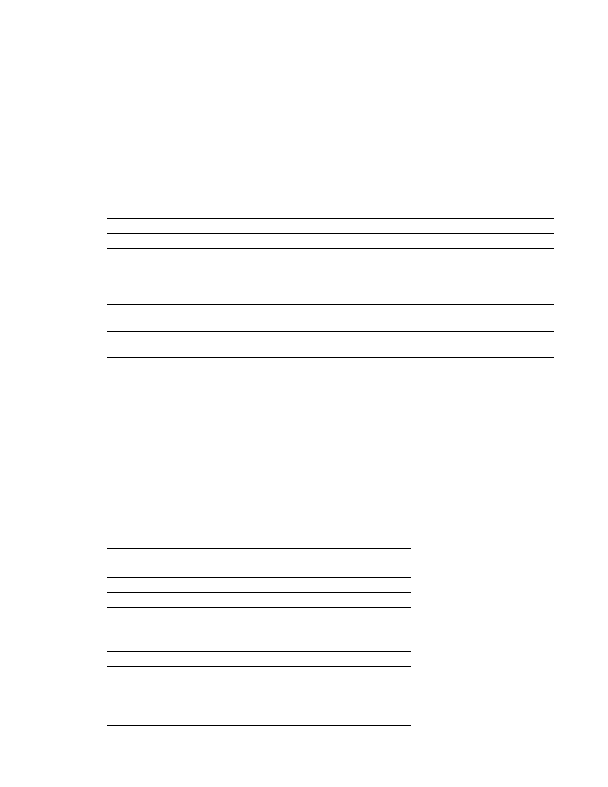
1.4 Specification Chart, continued
5
Model TC-101P TC-201P TC-501P
Dimensions (in.) 143/4x 81/4x 14 131/4x 141/4x 131/
(l x w x h) (cm) 37.5 x 13.3 x 35.6 33.7 x 36.2 x 33.7 40 x 47.6 x 43.2
Unit Weights 22 lbs (10.0 kg) 28 lbs (12.7 kg) 63 lbs (28.6 kg)
Reservoir Volumes 6 liters 10 liters 6 liters
Power Requirement 9A @ 115V / 1 / 60Hz 9A @ 115V / 1 / 60Hz 10A @ 115V / 1 / 60Hz
(105V - 125V) (105V - 125V) (105V - 125V)
4.5A @ 240V / 1 / 50Hz 4.5A @ 240V / 1 / 50Hz 5A @ 240V / 1 / 50Hz
(200V - 260V) (200V - 260V) (200V - 260V)
Section 2. Set Up
2.1 Location
Locate your circulator on a level surface free from drafts and direct sunlight. Do not place it near corrosive
fumes, excessive moisture, high room temperatures, or excessively dusty areas. Refrigerated circulators
must be four inches minimum away from walls or vertical surfaces so air flow is not restricted. Avoid voltage
drops by using properly grounded power outlets wired with 14 gauge or larger diameter wire and close to
the power distribution panel. To avoid low line voltage problems, do not use an extension cord.
4
153/4x 183/4x 17
2.2 Filling the Reservoir
Maximum fill level is one inch below the top of the reservoir. When in operation, add additional fluid to
compensate for any additional volume needed for external circulation.
Minimum liquid depth is enough to fully cover the heater, pump, and one inch of the temperature sensor
the proper fluid level is not maintained the heater coil may become exposed and possible damage to the
heater may result.
Warning: These units are equipped with Over Temperature Protection (OTP). Failure due to low
liquid level or failure to set OTP and properly immerse the heater may result in heater burnout
and triac failure. While operating, do not allow the heater to contact any potentially flammable
materials, such as plastic racks, as a fire hazard may result.
2.3 Reservoir Fluids
Use distilled water for temperatures from 10° to 90°C or a mixture of laboratory grade ethylene glycol and
water for temperatures -20° to 100°C. A variety of fluids can be used depending upon your needs. The fluid
must be chemically compatible with the reservoir and with 300 series stainless steel in the pump and heater.
The fluid must also be able to produce the temperature range desired.
For temperature stability of ±0.01°C, the viscosity should be 50 centistokes or less at the lowest operating
temperature to allow good fluid circulation and to minimize heating from the pump. Most single type of fluids
will be able to stabilize to ±0.01°C over a 100°C range. Use fluids that will satisfy safety, health, and
equipment compatibility requirements.
. If
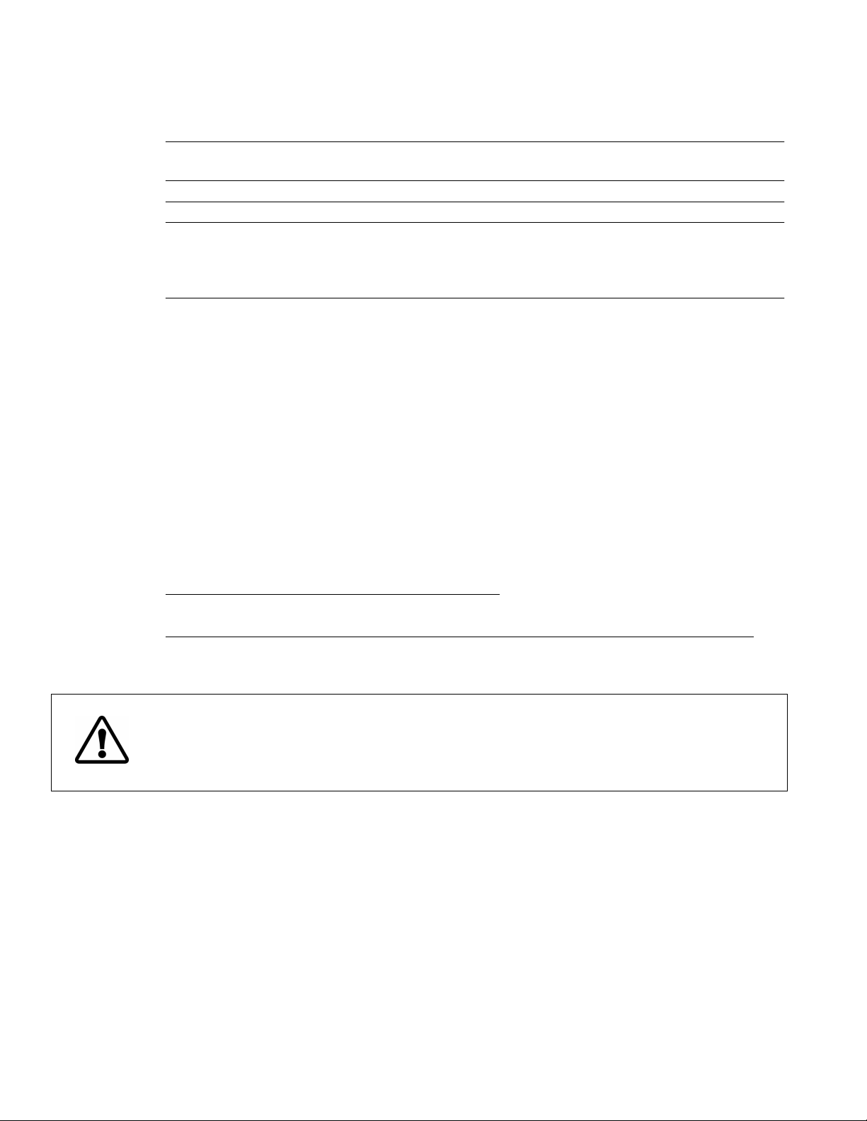
The following chart will help in selecting a fluid for your application. Stay within the fluid’s normal range for
best temperature stability, low vaporization, and safety.
You are responsible for proper selection and use of the fluids.
6
Extreme range operation should be avoided.
FLUID DESCRIPTION SPECIFIC HEAT NORMAL EXTREME
@25°C RANGE RANGE
Water 1.00 10°C — 90°C 2°C — 100°C
Ethylene Glycol 30% / Water 70% .90 0°C — 95°C -15°C — 107°C
Ethylene Glycol 50% / Water 50% .82 -20°C — 100°C -30°C — 100°C
Ethylene Glycol 100% .62 50°C — 125°C 0°C — 125°C*
Dynalene-HC 50™ .76 -50°C — 60°C -62°C — 60°C
DC510 50 cs Silicone Oil .39 50°C — 150°C 5°C — 270°C*
DC550 125 cs Silicone Oil .42 100°C — 200°C 80°C — 315°C*
*WARNING - Fluid’s flashpoint temperature.
DC fluids are manufactured by Dow Corning. Dynalene HC is a registered TM of Advanced Fluid Technologies, Inc.
DO NOT use the following fluids:
1. Automotive antifreeze with additives*
2. Hard tap water*
3. Deionized water with a specific resistance > 1 meg ohm
4. Any flammable fluids
5. Concentrations of acid or bases
6. Solutions with halides: chlorides, fluorides, bromides, iodides or sulfur
7. Bleach (Sodium Hypochlorite)
8. Solutions with chromates or chromium salts
* At temperatures above 40°C, additives or mineral deposits can adhere to the heater. If allowed to build up, the heater may
overheat and fail. Higher temperatures and higher concentrations of additives will cause a faster deposit build up. If buildup
occurs see Section 5.1 Maintenance - Heater.
WARNING: Do not use a flammable liquid as a fire hazard may result.
APPLICATION NOTES
At fluid's low temperature extreme:
1. Presence of ice or slush will adversely affect temperature stability.
2. Viscosity above 10 centistokes will adversely affect temperature uniformity.
3. High fluid viscosity and high speed pumping will generate heat in the fluid.
At fluid’s temperature above ambient without using refrigeration:
1. Without refrigeration and within 15°C of room temperature the viscosity should be 10 centistokes or less to
avoid friction heating of the fluid. Encourage heat loss by uncovering the fluid and lowering pump speed.
At fluid’s high temperature extreme:
1. Heat loss from vapor will cause poor temperature stability.
2. A fume hood may be required to prevent the buildup of vapors inside the room.
3. Use a cover and/or floating hollow balls to help prevent heat and vapor loss.
4. Fluid lost from vapor will have to be frequently replenished.

2.4 Fluid Connections
7
The pump inlet and outlet are threaded with female 1/4inch NPT to allow use of barbed tubing adapters or
hard plumbing.
Select tubing and fittings that are compatible with bath fluid and temperature range. If the pump inlet and
outlet are not used for external circulation, connect the inlet and outlet pipes with a short length of insulated
tubing. Or, plug the pipes with male nylon plugs (supplied) or with metal plugs (not supplied) for high
temperature use.
The nylon barbed tubing adapter fittings supplied are for applications from -20° to 93°C. Brass,
stainless steel or Teflon® fittings are recommended for applications above 93°C. Quick connectors are
not recommended as they restrict flow rate.
Some programmable models are not equipped with a refrigeration system. For operation of these nonrefrigerated models, the included cooling coil may be used to achieve bath temperatures within 15°C above
the ambient room temperature. The cooling coil also permits the bath temperature to be lowered more
rapidly, after operation at an elevated temperature. The cooling coil connections are located between the
circulating pump’s inlet and outlet connections at the rear of the bath’s controller. To use the cooling coil, slide
1
/4in. ID latex tubing from the water source over one of the coil’s connections and route another length of
the
tubing from the other coil connection to the drain.
2.5 Pump
A pressure & suction (DUPLEX) pump is built into each unit. The 5-speed DUPLEX pump is found in all
programmable controller circulators. It may be used for direct immersion of samples, closed loop circulation,
or circulating to an open bath. Speed selection is in the FUNCTION TUNINGmenu. (See Section 3.2)
Note:
When reducing the speed of a duplex pump, there may be a faint sound that is synchronous with the
flashing of the POWER light. The sounds are the pulses coming from the motor speed controller and are
normal.
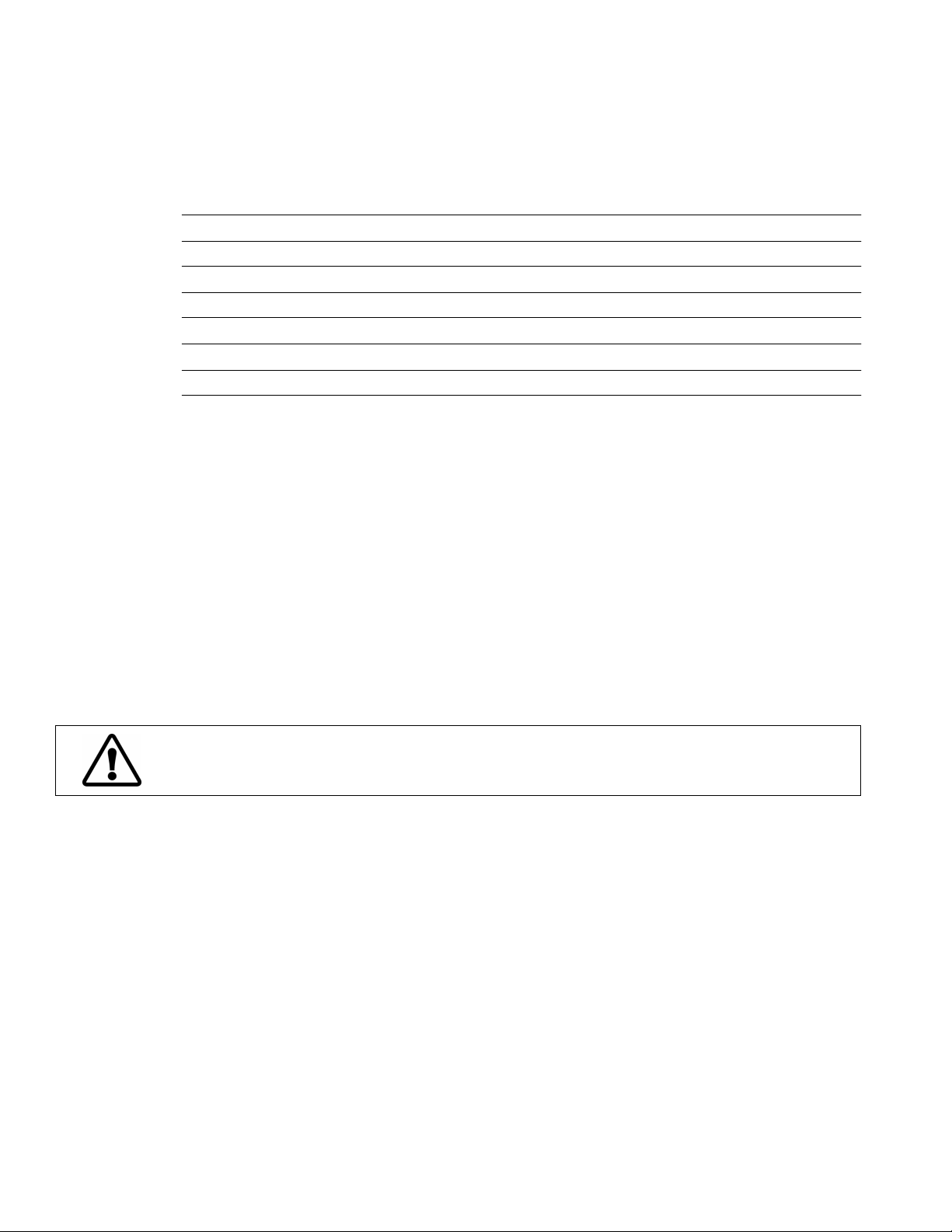
MAXIMUM OUTLET RATINGS
PUMP SELECTION SPEED PUMP TYPE 120V, 60Hz
1 = FULL 24 lpm / 5 psi
2 = HIGH 17.5 lpm / 2 psi
3 = MEDIUM 13.5 lpm / 1 psi
4 = LOW 12.5 lpm / 0.8 psi
5 = SLOW 11 lpm / 0.5 psi
The table uses the following criteria:
1. Maximum pump outlet flow rate is measured with no restriction on the pump outlet.
2. Maximum pump outlet pressure is measured in pounds per square inch (psi) at no flow.
3. The figures above were measured with water as the circulation fluid. Water has a viscosity of one
centistoke. High viscosity, low density fluid will reduce these figures.
4. Duplex pump suction inlet vacuum ratings are 75 percent of the outlet ratings shown.
5. When inlet and outlet are plugged, flow rate refers to internal bath circulation.
6. For 50Hz operation derate 60Hz values by 17%.
 Loading...