

Page 1
BROOKFIELD R/S+ RHEOMETER
Operating Instructions
Manual No. M08-219-B1211
(for serial numbers beginning with “304”)
with oces in:
BROOKFIELD ENGINEERING LABORATORIES, INC.
11 Commerce Boulevard, Middleboro, MA 02346 USA
TEL508-946-6200
FAX508-946-6262
Boston • Chicago • London • Stuttgart • Guangzhou
or
800-628-8139
I
NTERNET
http://www
SPECIALISTS IN THE
MEASUREMENT AND
CONTROL OF VISCOSITY
(USAexcluding
.brookeldengineering.com
MA)
Brookfi eld Engineering Labs., Inc. Page 1 Manual No. M08-219-B1211
Page 2

Page 3

Table of Contents
I. General Description ....................................................................................................... 7
I.1 Use of the Rheometer ...................................................................................................7
I.2 Measuring Principle .......................................................................................................7
II. System Confi guration ............................................................................................... 8
II.1 R/S+ Rheometer ..........................................................................................................8
II.2 Measuring Geometries (Spindles or Bobs with Sample Cups) .................................... 10
II.3 Computer System Requirements .................................................................................10
III. Instrument Installation .............................................................................................. 11
III.1 Mounting the Stand .....................................................................................................11
III.2 Electrical Connections ..................................................................................................12
III.2.1 Temperature Sensor PT100 ............................................................................... 12
III.2.2 AC Adapter .........................................................................................................13
III.2.3 Printer Connection .............................................................................................13
III.3 Connecting Temperature Controlled Measuring Devices ..........................................14
III.2.4 Computer Connection ........................................................................................14
III.3.1 Connecting the Water Jacket ............................................................................. 14
III.3.2 Connecting the Optional Cone/Plate Attachment ...............................................16
III.3.3 Connecting the KE Cooling Device .................................................................... 17
IV. Environment, Handling, Cleaning and Maintenance ............................................. 19
IV.1 Operating Environment and Storage ...........................................................................19
IV.2 Handling .......................................................................................................................19
IV.3 Cleaning .......................................................................................................................19
IV.4 Maintenance ................................................................................................................ 20
V. Measuring Systems .................................................................................................. 21
V.1 Measuring Directly in the Sample Container ................................................................. 21
V.2 Measurement by Filling the Sample Cup .......................................................................22
V.3 Measurement with Water Jacket Assembly ...................................................................22
V.4 Measurement with Cone/Plate or Plate/Plate Measuring Systems ............................... 23
VI. Operation and Menu System ................................................................................... 25
VI.1 Keyboard ..................................................................................................................... 26
VI.2 Menu System of R/S+ Rheometer ...............................................................................28
VI.3 Selecting from Lists ..................................................................................................... 29
VI.4 Input of Numerical Values and Alphanumeric Texts ..................................................... 30
VI.5 Menu Entries (MAIN Menu) ......................................................................................... 31
VI.5.1 MAIN Menu → Run Single ................................................................................ 32
VI.5.2 MAIN Menu
VI.5.3 MAIN Menu → Run Program ..............................................................................34
VI.5.4 MAIN Menu → Remote .......................................................................................36
VI.5.5 MAIN Menu → Utilities .......................................................................................37
VI.5.6 MAIN Menu → Confi guration .............................................................................. 37
VI.6 Menu Entries in the Utilities Menu ............................................................................... 37
VI.6.1 Utilities → Zero Calibration .................................................................................38
→ Single Measurement .................................................................32
Page 4

VI.6.2 Utilities → Edit Program .....................................................................................38
VI.6.3 Utilities → Print Programs ..................................................................................42
VI.6.4 Utilities → Measuring Systems ...........................................................................42
VI.6.5 Utilities → Print Memory .....................................................................................43
VI.6.6 Utilities → Clear Memory ....................................................................................44
VI.6.7 Utilities → Measure Temperature ....................................................................... 44
VI.7 Menu Entries of the Confi guration Menu ..................................................................... 45
VI.7.1 Confi guration → Set Output Mode .....................................................................45
VI.7.2 Confi guration → Set MeasCount Mode .............................................................. 46
VI.7.3 Confi guration → Reset MeasCount ..................................................................... 46
VI.7.4 Confi guration → Set Time/Date ..........................................................................46
VI.7.5 Confi guration → Set RS-232 Parameters ..........................................................47
VI.7.6 Confi guration → Language .................................................................................49
VI.7.7 Confi guration → Service .....................................................................................49
VI.8 Serial Data Transfer via the RS-232 Interface .............................................................49
VII. Measurements ............................................................................................................ 51
VII.1 Measuring in Manual Mode ......................................................................................... 51
VII.2 Measuring with Water Jacket ...................................................................................... 51
VII.3 Measurement with Cone/Plate Attachment ................................................................. 51
VII.4 Measurement in Remote Mode ................................................................................... 52
VIII. Technical Data ........................................................................................................... 53
Appendix A ........................................................................................................................ 55
A.1 Data Sheets of Standard Measuring Systems ..............................................................55
A.2 Error Messages ............................................................................................................. 57
A.3 Pin Assignment of the Serial Data Cable ......................................................................60
A.4 Requirements to the AC Power Connecting Cables .....................................................60
Appendix B: Calibration Check Procedure .................................................................... 62
B.1 Using Rheo 3000 ..........................................................................................................62
B.2 Stand-alone Mode ......................................................................................................... 63
Appendix C: RS4SSTB Rheometers for Measuring in Brabender Units (BU) ...........64
C.1 Adjusting the BU Factor ................................................................................................65
C.2 Test Program ................................................................................................................. 65
Appendix D: R/S-SST+ - Soft Solid Tester ..................................................................... 66
D.1 Operating the R/S-SST+ Soft Solids Tester .................................................................. 66
D.1.1 Running a Sample Using Software Control .......................................................66
D.1.2 Soft Solids Analysis Functions ........................................................................... 66
D.1.3 Running a Sample in Stand-Alone mode. ..........................................................67
D.1.4 Editing and Running Programs .......................................................................... 68
D.2 Getting Started in Soft Solids Testing ...........................................................................68
D.2.1 The Constant Rate Test .....................................................................................68
D.2.2 The Creep Test ................................................................................................... 69
D.3 A Few Tips To Get You Started .....................................................................................70
D.3.1 Vane selection ....................................................................................................71
D.3.2 Container Dimensions ........................................................................................71
Page 5

D.3.3 Setting Up Vanes In Measuring System Editor .................................................. 71
D.4 Vane Constants For The Soft Solids Tester .................................................................72
D.4.1 Stress Constant: τ
D.4.2 Strain/Rate Constant: K-Gamma .......................................................................72
....................................................................................... 72
prom.
Appendix E: R/S Portable Rheometer ...........................................................................74
E.1 Technical Specifi cations ...............................................................................................74
E.2 Electrical Connections .................................................................................................76
E.3 Measurement Range ...................................................................................................77
E.3.1 Data Sheets of Standard Measuring Systems ...................................................77
E.4 R/S Portable Components ...........................................................................................78
E.5 Operation Under Battery Power ...................................................................................79
Appendix F: Online Help and Other Resources ...........................................................80
Appendix G: Warranty and Repair Service .................................................................... 81
Page 6

Page 7

I. General Description
This section has general information about the instrument and operating principles.
I.1 Use of the Rheometer
The R/S+ Rheometer will measure viscosity of Newtonian and Non-Newtonian materials in
controlled shear rate (CSR) or controlled shear stress (CSS) modes. The instrument can measure
simple viscosity at a given speed or shear rate, or measure fl ow properties with a fl ow curve at
shear rates up to ~1,200 sec-1.
In controlled stress mode, the instrument can do a direct yield test (stress ramp) and indicate
elasticity with creep/recovery tests.
I.2 Measuring Principle
The R/S+ Rheometer is a rotational, controlled shear stress instrument which can be operated in
controlled shear rate mode.
Concentric cylinders, measuring cones and plates are available as a measuring system. The
measuring sample is positioned in a measuring gap between the stationary measuring cup and
the rotating measuring bob (Searle-principle), respectively between the rotating cone or plate and
the stationary lower plate (cone/plate, cone/cone measuring system).
The measuring drive developed for this instrument operates with a high precision, dynamic drive
system with optical encoder for absolute position measurement of spindle geometry.
The R/S+ measuring drive can operate at a pre-set of speed (shear rate) or pre-set of torque (shear
stress). Measurements may be made in manual mode (without PC) or under PC control with Rheo
3000 software. Note that the creep measurements require a computer system with Rheo 3000
software.
Both CSR and CSS measurements can be carried out manually (without PC support) or with a
computer system and Rheo 3000 software.
Brookfi eld Engineering Labs., Inc. Page 7 Manual No. M08-219-B1211
Page 8

II. System Confi guration
The R/S+ Rheometer system consists of:
•
Rheometer head containing electronic unit and measuring drive integrated in one
housing
•
Lab Stand with removable catchment table
•
AC Adapter
Available Accessories:
•
Coaxial cylinder measuring system (see Appendix A)*
•
Temperature measuring sensor Pt100*
•
Water jacket assembly
•
Bath/Circulator
•
Rheo 3000 software for control of R/S+ by PC
•
Vane spindles
•
BU Spindles
•
Cone/Plate and Plate/Plate Assembly
*
The accessories in bold print are necessary for a minimal confi guration. See Figure II-1
for illustration of the R/S+ Rheometer System Components.
Available Services:
•
Startup Assistance
•
Instrument Training
•
Rheo 3000 Software Training
II.1 R/S+ Rheometer
Instrument features include:
•
Digital control of rotational speed and torque
•
Automatic adjustment of control parameters during measurement
•
Direct indication of measured and calculated values of speed/shear rate, torque/shear
stress, viscosity, temperature, and time
Data storage (measured values)
•
Data output to a printer (parallel)
•
User support with LCD and keypad
•
Built-in system interface with serial standard interface (RS232) for connection to a
•
computer or other serial data-logger
Printing and serial data-transmission during the test
•
The R/S+ Rheometer can either be operated manually using the keypad on the front panel or it
can be operated under computer control. The R/S+ Rheometer is supplied with a direct current
drive by the AC Adapter.
Brookfi eld Engineering Labs., Inc. Page 8 Manual No. M08-219-B1211
Page 9
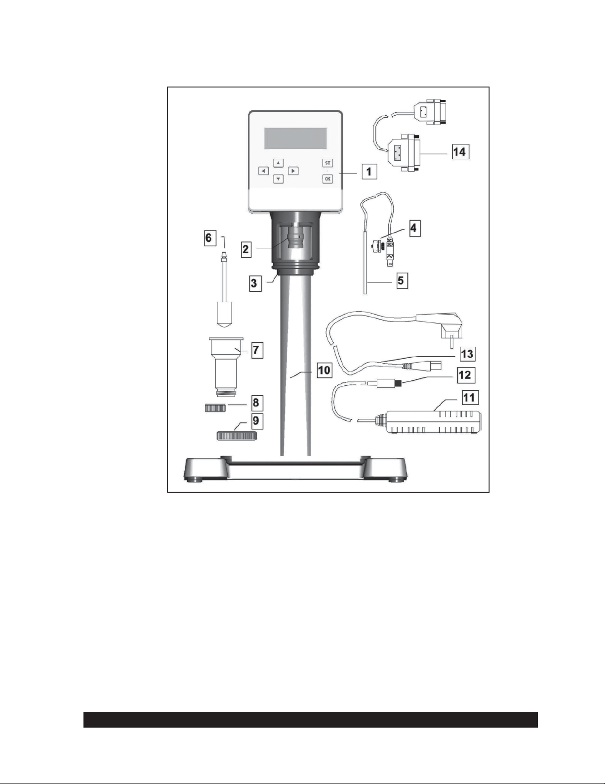
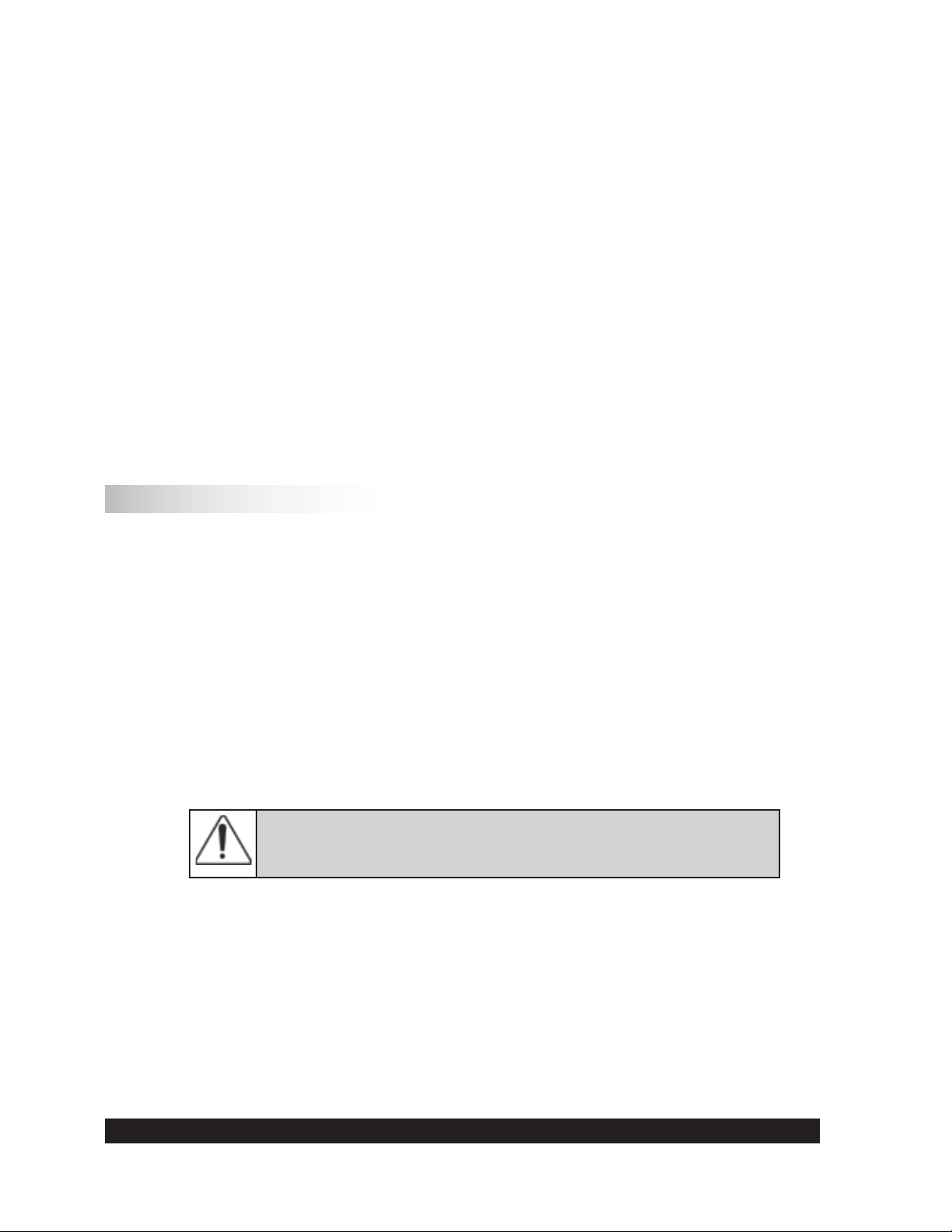
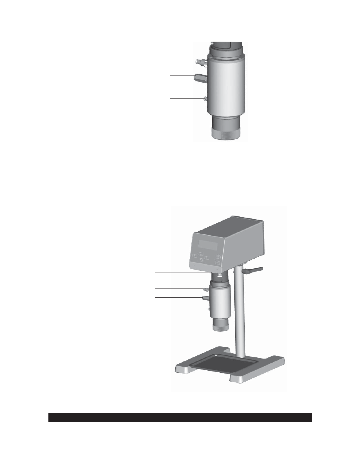
R/S+ Rheometer
1 R/S+ Rheometer Head
2 Measuring Bob Coupling
3 Mounting Flange
4 Pt100 Clamp Fixture (accessory)
5 Pt100 (temperature probe accessory)
6 Standard Measuring Bob (accessory)
7 Standard Measuring Cup (accessory)
8 Measuring Cup Bottom or Thread Protection (accessory)
9 Measuring Cup Screw Fitting
10 Lab Stand
11 AC Adapter
12 Direct Current Plug (to Rheometer head)
13 AC Power Cable
14 RS232C Cable (accessory)
Fig. II-1: Confi guration of the R/S+ Rheometer
Brookfi eld Engineering Labs., Inc. Page 9 Manual No. M08-219-B1211
Page 10

II.2 Measuring Geometries (Spindles or Bobs with Sample Cups)
Measuring devices are not included in the base instrument price and must be ordered
separately.
Measuring devices that can be used with the R/S+ include:
• Coaxial geometry measuring systems (see Appendix A) with and without built-in temperature
sensor Pt100
• Water Jacket Assembly for use with the coaxial cylinder measuring system in temperature
range -10°C to +180°C
• Vane spindles (see Appendix D) for measuring soft solids
• BU Spindle (see Appendix C) for measuring joint compound in Brabender units
• Cone/Plate Assembly for measuring small sample volumes <1mL
II.3 Computer System Requirements
The computer system control of the R/S+ is optional and provides automatic measuring, data plots,
printing (full reports or data plots) as well as analysis of results and quality control charts.
The recommended computer system has the following minimal system requirements:
- CPU / 1 GHz
- 512 MB RAM (main memory)
- 500 MB free hard disk capacity
Compatible operating system includes:
- Microsoft Windows 2000™, Windows XP™, Windows 7™ or Vista™
- mouse and keyboard
- VGA graphic card and monitor
- 1 free serial interface
Brookfi eld Engineering Labs., Inc. Page 10 Manual No. M08-219-B1211
Page 11
III. Instrument Installation
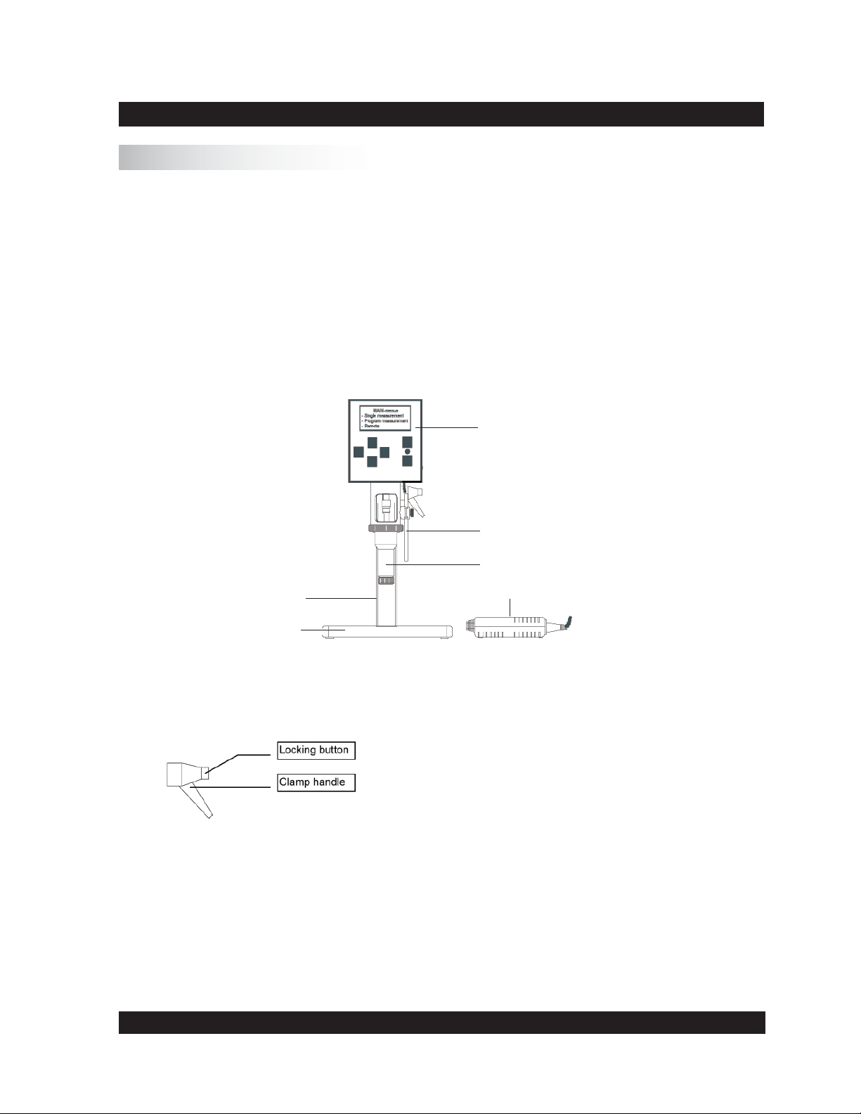
III.1 Mounting the Stand
The stand consists of:
the stand base plate
•
the stand column with rheometer
•
A 5 mm Hex wrench and bolt DIN 912 M8 x 40 are supplied for mounting.
The stand column is connected to the stand base plate with a bolt. The proper orientation of the
column is set with a pin in the bottom of the column which fi ts into a hole on the stand base.
Rheometer
Stand
Base
Fig. III-1.: Rheometer R/S+ (minimum confi guration)
Hints for height adjustment of the stand:
To change the height adjustment of the stand, you must release the
clamp handle and move the stand to the desired height.
Caution: Hold the rheometer as you release the clamp handle!
You can press the locking button to change the clamp handle position without screwing/unscrewing the thread. After adjustment of the
height screw, tighten clamp handle thread.
Fig. III-2.: Stand Height Adjustment Hints
Temperature Sensor Pt100
Coaxial Cylinder System
AC Adapter
Brookfi eld Engineering Labs., Inc. Page 11 Manual No. M08-219-B1211
Page 12

III.2 Electrical Connections
Connections for the electrical components of the R/S+ Rheometer are located on the back of the
instrument head.
Parallel Printer Connection
RS232C Computer Connection
Socket for Pt100 Temperature Probe
Socket for AC Adapter
ON/OFF Switch
Fig. III-3: Operating and connecting elements at the back side of the measuring head
All cables to and from the R/S+ Rheometer may be connected or
disconnected only when the instrument is turned off!
III.2.1 Temperature Sensor PT100
The connecting cable for the temperature sensor Pt100 (100 ohm DIN alpha RTD) is inserted into
the socket labeled “Pt100” at the back of the rheometer head.
If you use standard cylindrical measuring cups (CC8, CC14 etc.), put the Pt100 into the mounting
clamp fi xture and align it parallel to the measuring system by attaching it to the mounting fl ange
of the rheometer.
Fig. III-4: Pt100 connection and mounting
Brookfi eld Engineering Labs., Inc. Page 12 Manual No. M08-219-B1211
Page 13
Insert the plug for the Pt100 connector in the back of the rheometer head.
Since viscosity is a function of temperature, the temperature should be preferably measured in the
test fl uid. For this purpose, the standard measuring systems 8 mm to 40 mm DIN can be equipped
with a Pt100 in the measuring cup bottom when the water jacket is used. If you use a measuring
system with built-in Pt100, this is where you will insert the cable VK-Pt/RC.
III.2.2 AC Adapter
Do not use a power supply other than the AC adapter delivered by Brookfi eld for the R/S+
Rheometer.
Connect the AC adapter using a grounded plug to avoid electric
shock or damage to the system components!
Connecting the AC adapter:
Turn the R/S+ Rheometer off with the “POWER” switch at the back side of the
instrument.
Connect the RS+ power cord into the AC adapter.
Insert the socket of the DC cable into the “DC” connector port at the back side of the
instrument.
Plug the power cable into a grounded AC power socket.
Turn the R/S+ Rheometer on.
-
Do not leave the power supply plugged into the AC power socket when the cable to the
rheometer is un-plugged!
Before disconnecting the rheometer from the AC supply, be sure that the instrument is
switched off.
III.2.3 Printer Connection
A printer can be connected directly to the interface connector of the rheometer when measuring
without PC control. You must preset “Printer” as the output device to print the measuring values
during measurement (see Section VI). The printer should have a parallel printer interface. USB
printers are not supported.
Turn off the rheometer with the AC power switch at the back of the R/S+.
Insert the printer connecting cable into the “PRINTER” port on back of the
instrument.
Turn the R/S+ Rheometer on.
-
A standard printer cable can be used as a printer connecting cable. This cable is supplied with the
printer in most cases. To print data values from the R/S+ Rheometer, any (parallel) printer which
can operate in ASCII character mode may be used.
Brookfi eld Engineering Labs., Inc. Page 13 Manual No. M08-219-B1211
Page 14
III.2.4 Computer Connection
If the R/S+ Rheometer has to be used in “REMOTE” mode with a PC (Rheo 3000 program
package) or with serial data-terminal for data logging, the RS232C cable needs to be connected
to the 25 pin port labeled “RS232” on the back of the instrument.
Turn the R/S+ Rheometer off with the “POWER” switch at the back of the
•
instrument.
Turn the computer system off.
•
Connect the rheometer data cable to the 25 pin port labelled “ RS232” on the back of
•
the R/S+ Rheometer.
Connect the Peltier data cable to the port labelled “ RS232/Peltier” on the back of the
•
rheometer head.
Turn the R/S+ Rheometer and your computer system on again.
•
You must use the computer cable supplied by Brookfi eld - other cables will not work!
III.3 Connecting Temperature Controlled Measuring Devices
Water Jacket Assembly: for use with the cylinder measuring system, in the temperature
•
range of -10°C to +90°C (liquid’s temperature control).
Cooling Device KE: expands the temperature range from -20°C to +180° in conjunction
•
with the FTKY3 temperature control device or CONE/PLATE ATTACHMENT.
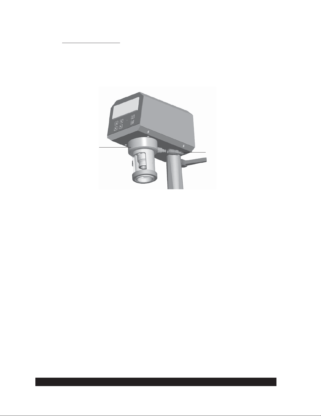
III.3.1 Connecting the Water Jacket
The Water Jacket FTKY3 is an optional accessory for use with the coaxial cylinder measuring
system in the temperature range -10°C to +90°C.
The water jacket should be used only in the temperature range
-10°C to +90°C unless the KE cooling device is installed, in which
case, the temperature range is -20°C to +180°C!
Brookfi eld Engineering Labs., Inc. Page 14 Manual No. M08-219-B1211
Page 15
Thread Joint for Connection of
Measuring Cup to Mounting Flange
Hose Connection of Flow Output
Temperature Sensor Pt100
Hose Connection of Flow Input
Measuring Cup Bottom
Fig. III-5: Water Jacket Assembly
Mounting the Water Jacket Assembly:
When using the KE cooling device, mount the cooling device fi rst (see Section
•
III.3.3).
Attach the jacket on the mounting fl ange from below and tighten the thread.
•
Connect the tubes from the water bath to the jacket.
•
Connect the jacket’s built-in Pt100 cable to the R/S+ Rheometer.
•
Cooling Device KE-FTK/RC30
Tube Connector
Temperature Sensor Pt100
Tube Connector
Water Jacket
Fig. III-6: Operation with the Water Jacket Assembly FTKY3 and Cooling Device KE
Brookfi eld Engineering Labs., Inc. Page 15 Manual No. M08-219-B1211
Page 16

Bath/Circulator Connection to the Water Jacket
The tubes are used to connect the bath to the R/S+ water jacket.
The tubes are connected to the quick fi tting couplings on the jacket assembly. The coupling has a
female part which is put into the tubing, and a male part built into the jacket assembly. To connect
the two, pull back on the female section slide ring and put the connector onto the jacket (male)
connector, releasing the slide ring.
Water jacket without cooling device KE is only used in the
temperature range -10°C to +90°C!
The jacket FTKY3 can be used in the temperature range -20°C to +180°C when used with the
optional KE cooler (for tap water cooling of the rheometer bearings).
The following working fl uids are usually used in the temperature bath:
-10°C to +90°C Water - Glycol Mixture
-20°C to +180°C Bath Oil
Suitable bath fl uids can be ordered from BROOKFIELD.
III.3.2 Connecting the Optional Cone/Plate Attachment
Turn off the R/S+.
•
When using the KE cooling device, mount the cooling device fi rst (see Section
•
III.3.3)
Set the “CONE/PLATE ATTACHMENT” from below the mounting fl ange and tighten
•
the thread. Before tightening, check that the guide pin of the measuring device (see Fig.
III-7) is in the slot of the R/S+ mounting fl ange!
Connect the bath tubes to the “CONE/PLATE ATTACHMENT”.
•
Connect the Cone/Plate and temperature probe cable to the R/S+.
•
For mounting the cone/plate or plate/plate measuring systems to the measuring device
•
refer to Section V.
Bath/Circulator Connection to the Cone/Plate Attachment
The hoses are connected to the quick fi tting couplings on the cone/plate assembly. The coupling
has a female part which is put into the tubing, and a male part built into the jacket assembly. To
connect the two, pull back on the female section slide ring and put the connector onto the jacket
(male) connector, releasing the slide ring.
Brookfi eld Engineering Labs., Inc. Page 16 Manual No. M08-219-B1211
Page 17
The following working fl uids are usually used in the temperature bath:
-10°C to +90°C Water - Glycol Mixture
-20°C to +180°C Bath Oil
Suitable bath fl uids can be ordered from BROOKFIELD.
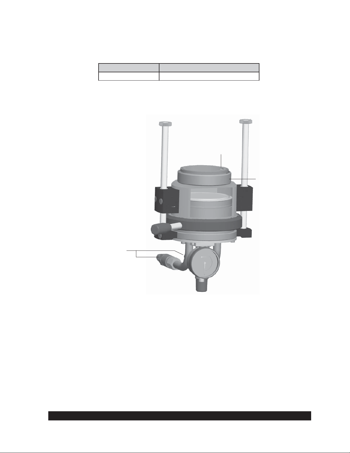
Guide Pin
Screw Connection for
Mounting Flange
Bath Tubing Connectors
Fig. III-7: CONE/PLATE ATTACHMENT for cone/plate and plate/plate systems
III.3.3 Connecting the KE Cooling Device
The optional cooling device KE COOLING ATTACHMENT must be used where the test
temperature is below -10°C or above 90°C. When using the KE COOLING ATTACHMENT,
the temperature range is expanded from -20°C to +180°C.
Brookfi eld Engineering Labs., Inc. Page 17 Manual No. M08-219-B1211
Page 18
Attachment Procedure
Turn off the R/S+.
•
Lift the KE COOLING ATTACHMENT to the R/S+ Rheometer from below and tighten
•
the thread.
Connect the tubes of the cooling line to the KE COOLING ATTACHMENT (see Figure
•
III.8).
Cooling Device KE
Fig. III-8: Cooling Device KE
Hose Connection
• The tubes for the KE Cooling Device are connected with quick connect couplings.
Brookfi eld Engineering Labs., Inc. Page 18 Manual No. M08-219-B1211
Page 19
IV. Environment, Handling, Cleaning and Maintenance
IV.1 Operating Environment and Storage
Find a convenient work place for the installation of the R/S+ Rheometer. There should be enough
room to place the rheometer, the measuring systems, the measuring substances and the peripheral
devices (e.g. printer, computer and bath/circulator). You need a grounded AC plug to operate
the R/S+ Rheometer and additional plugs for the connection of each peripheral device (i.e. Bath,
Peltier). Your operating environment and the place where you store the R/S+ Rheometer should
not be extremely hot, extremely cold or extremely moist. Places with large temperature and air
humidity variations should be avoided. Be sure that the R/S+ Rheometer is not exposed to the
following:
heavy dirt or dust
•
direct sun
•
•
objects that emit heat (e.g. heating radiators)
•
objects with a strong electromagnetic fi eld (e.g. loudspeakers, motors etc.)
•
liquids or corrosive chemicals
IV.2 Handling
The R/S+ Rheometer is designed to endure light bumps or vibration. Avoid dropping it or exposing
it to heavy shock!
Never lift your RS+ Rheometer at the measuring bob coupling or with
the measuring bob attached to the instrument.
Always disconnect the bob at the bob coupling before removing the
sample cup!!!!
The rheometer motor will automatically turn off if the maximum torque (50 mNm) is exceeded.
IV.3 Cleaning
The paint coat of the R/S+ Rheometer resists most usual solvents and weak acids. Use a dry, clean,
soft and nap-free piece of cloth to clean the housing. Use neutral detergent liquids, if necessary.
Do not use chemical products such as strong solvents or strong acids to
clean the housing, especially the keyboard.
Brookfi eld Engineering Labs., Inc. Page 19 Manual No. M08-219-B1211
Page 20

IV.4 Maintenance
The R/S+ Rheometer system is designed for long-term operation. Should the instrument require
repair, contact Brookfi eld or your Brookfi eld dealer.
Only authorized service personnel may work on the control
electronics, all accessories, the measuring drive, as well as the AC
Adapter and all electric circuits and connections!
Measurement accuracy can be checked by the user at any time. We recommend that the
measurements be done with Brookfi eld viscosity standard fl uids (mineral oils) as recommended
for each individual spindle geometry.
You must:
Use temperature control (i.e. water jacket and circulating bath)
•
Select the appropriate measuring system
•
Carry out measurements at the following pre-set M (‰ torque): 250‰, 500‰ and 750‰
•
Read viscosities from the display
•
In case of instrument failure (or severe deviation from the preset value), contact Brookfi eld or
your Brookfi eld Dealer.
Brookfi eld Engineering Labs., Inc. Page 20 Manual No. M08-219-B1211
Page 21
V. Measuring Systems
V.1 Measuring Directly in the Sample Container
You may immerse the measurement system directly into a container of sample by removing the
cap on the bottom of the immersion cups.
When using the double gap bob measuring system, do not damage the “O” ring which forms the
seal between the inner and outer parts of the sample cup. To clean, the inner section is removed
by unscrewing the (stainless steel) ring at the bottom and then GENTLY push the inner section
out through the bottom of the outer section. Take care not to damage or stretch the O-ring seal
during removal! Insert the inner part again and screw the ring back on.
General steps for direct immersion of the measuring system into the bath:
Lift the coupling sleeve of the measuring bob coupling (the ring is visible).
•
Insert the measuring bob into the measuring bob coupling.
•
Lower the coupling sleeve (the ring is covered).
•
Fasten the measuring cup at the measuring cup mounting fl ange with the measuring cup
•
ring.
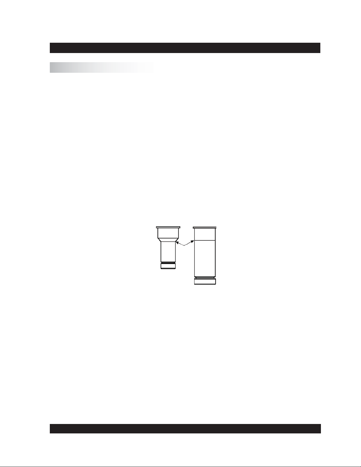
Immerse the measuring cup into the substance up to the ring mark or up to the point where
•
the diameter of the measuring cup increases.
Fig. V-1: Depth of immersion
Do not get sample in or onto the measuring bob coupling.
After making your viscosity measurement, unscrew the measuring cup ring and remove the
measuring cup. Open the measuring bob coupling, and remove the measuring bob.
Clean the measuring cup and measuring bob carefully. Do not use abrasive cleaning tools, and
always prevent scratches! Store measuring bobs on a soft pad.
Brookfi eld Engineering Labs., Inc. Page 21 Manual No. M08-219-B1211
Page 22
V.2 Measurement by Filling the Sample Cup
Fill the measuring cup with your material (see Appendix A.1 for sample volume). Avoid air
bubbles when fi lling the sample as they can affect the repeatability of the test!
Place the measuring bob into the measuring cup. Lift the coupling sleeve (the ring is visible).
Insert the complete measuring system into the measuring cup mounting fl ange from below and
screw on using the measuring cup ring. Now, insert the measuring bob shaft completely into the
measuring bob coupling and lower the coupling sleeve (the ring is covered).
If you want to measure with temperature control, the bath/circulator must be pre-set at the desired
temperature and you should wait until bath liquid and sample are at test temperature.
To remove the measuring system after the viscosity measurement has been completed, fi rst open
the measuring bob coupling and then unscrew the measuring cup thread.
When unscrewing the measuring cup, you must hold the measuring
system tightly with one hand to avoid dropping the cup and bob!
Clean the measuring cup and measuring bob carefully with a soft cloth to avoid scratches!
V.3 Measurement with Water Jacket Assembly
Install the FTKY3 jacket by removing the measuring cup ring on the rheometer (see Figure III.5).
Attach the jacket to the rheometer using the ring built onto the top of the jacket.
Connect the tubing from the bath (the bath outlet to the bottom tubing connection of the jacket;
the bath inlet to the top of the connection on the water bath) to the jacket , and connect the Pt100
on the jacket to the Pt100 socket on the back of the rheometer.
When using disposable measuring systems, insert the disposable measuring cup into the receptacle.
Fill the measuring cup with the sample. (See Appendix A.1 for sample volumes).
Avoid air bubbles when fi lling the sample as they can affect the repeatability of the test!
Place the measuring bob in the measuring cup. Lift the coupling sleeve (ring is visible). Insert the
cup and bob into the jacket from below and screw on using the measuring cup ring. Insert the bob
shaft into the measuring bob coupling and lower the coupling sleeve (ring is covered).
Set the water bath to test temperature. After the bath is at the test temperature, wait 15 minutes
to ensure that the sample, cup and bob are at test temperature.
Brookfi eld Engineering Labs., Inc. Page 22 Manual No. M08-219-B1211
Page 23
To remove the measuring system after the measurement, fi rst open the coupling sleeve for the
bob, then unscrew the measuring cup ring.
When unscrewing the measuring cup, you must hold the measuring
system tightly with one hand to avoid dropping the cup and bob!
When using disposable measuring cups, eject the disposable measuring cup with the pusher.
V.4 Measurement with Cone/Plate or Plate/Plate Measuring Systems
Installing and adjusting the measuring cone or measuring plate
When installing a cone or plate, the lower plate must be in the down position (move the locking
lever to the left and gently pull the lower plate down).
When releasing the bayonet lock, the measuring device has to be held
tightly from below.
Loosen the set screw on the cone or plate and push the cone or plate bottom up, setting the shaft
length to the minimum.
Lift the coupling sleeve (red ring mark should be visible). Insert the cone or plate from below into
the measuring coupling. Lower the coupling sleeve (ring is covered) to attach the spindle.
Turn the adjusting screw on the plate down to the lowest position. Raise the plate to the top
position and secure it with the bayonet lock (position “closed”).
The actual distance between spindle and plate has to be adjusted to approximately 1 mm by
turning the adjusting screw up. Set the screw mark to “0” with approximately 1 mm between
cone and plate.
The dial indicator should also be set to mark “0” for distance control. Unlock the spindle shaft
to bring the spindle onto the plate, and tighten the cone set screw to fi x the shaft.
The plate is now adjusted to 50 μm. The adjustment ring lowers the plate down when turned
clockwise (looking down onto the adapter), and raises it up by turning the ring counter-clockwise.
Lower the plate to 0.5 mm by turning the adjustment ring clockwise for one complete revolution.
Now raise the plate, but not all the way back to the zero position; stop at the “5” mark in the ring
which sets the gap to 50 μm.
Brookfi eld Engineering Labs., Inc. Page 23 Manual No. M08-219-B1211
Page 24

Measurement
Open the bayonet lock and lower the plane-table. Apply the sample to be tested. Lift up the planetable and fi x the bayonet lock. Now, the measurement can start.
Remove excess sample from around the cone or plate before starting the
measurement.
If temperature control is required, a bath/circulator must be connected. The bath must be set at
the desired temperature, and you should wait until the bath and cone/plate accessory have reached
test temperature.
Brookfi eld Engineering Labs., Inc. Page 24 Manual No. M08-219-B1211
Page 25

VI. Operation and Menu System
The following section summarizes the operation and the menu system of the R/S+ Rheometer for
both manual and PC-controlled measurement.
Menu prompts for the R/S+ Rheometer in stand-alone mode are available in the following
languages:
English
•
German
•
The language is selected via the menu level Confi guration→Language (if English is active)
or Konfi guration→Sprache (if German is active). For more details on language selection, see
Section VI.7.6.
After applying power to the R/S+ Rheometer, the LCD displays the following information for
a few seconds:
name of the rheometer
•
software version of the fi rmware installed in the instrument
•
serial number of the instrument
•
date and time
•
Example:
R/S+ Rheometer
Ver.: 9.00 #xxxxxx
27.10.11 15.12
©Brookfi eld Engineering
About fi ve seconds later, the instrument checks the voltage of the power supply. The displayed
voltage should be in the range of 14.9 to 16V. If the voltage is outside this range, contact Brookfi eld
or your local Brookfi eld dealer.
Example:
Voltage Check:
VCC:15.25 V
This message is displayed for about 3 seconds and then the MAIN menu is displayed. A brief
summary, in Section VI.4, of the rheometer keyboard and the corresponding rheometer functions
may be helpful before you get to the complete description of the menu.
Brookfi eld Engineering Labs., Inc. Page 25 Manual No. M08-219-B1211
Page 26

VI.1 Keyboard
- Select previous menu entry
- Input: increment numerical
value/letter
- Select next menu entry
- Input: decrement numerical
value/letter
MAIN MENU
- Single measurement
- Program measurement
- Remote
>
R/S + RHEOMETER
ON
ST
START/STOP
- Back to parent menu
- Abort
- Start of measurement
- Abort measurement
OK
OK
- Accept
- Select
- One digit to the right
- One digit to the left
All user inputs are made using the six keys located below the LCD. Some of the keys have
multiple uses, i.e. their function depends on the current operation. The following table shows
the keyboard functions in detail.
Keypad layout of the R/S+ Rheometer
Key Operation Function of Key Example
1) Menu
2) Input of
numerical values
3) Selection from list
1) Menu
2) Input of
numerical values
3) Selection from list
1) Menu
1) Go to previous menu
entry (above active one)
2) Increment
3) List entry above active
entry (previous)
1) Go to next menu entry
(below active one
2) Decrement
3) List entry below active
entry (next)
1) Go to previous menu
entry (above active one)
1) Utilities → Remote
2) 8 → 9
A → B
3) Select meas. system
CC25/30 → CC37/30
1) Remote → Utilities
2) 5 → 4
F → G
3) Select meas. system
CC37/30 → CC25/30
1) Utilities → Remote
2) Input of
numerical values
2) One digit to the right
2) 100.00 → 100.00
Test → Test
3) Selection from list
1) Menu
3) List entry above active
entry (previous)
1) Go to next menu entry
3) Select meas. system
CC25/30 → CC37/30
1) Remote → Utilities
(below active one)
2) Input of
numerical values
2) One digit to the left
2) 100.00 → 100.00
Test → Te st
3) Selection from list
3) List entry below active
entry (next)
3) Select meas. system
CC25/30 → CC37/30
Brookfi eld Engineering Labs., Inc. Page 26 Manual No. M08-219-B1211
Page 27

Key Operation Function of Key Example
1) Menu
1) Return to parent menu
(turn page downward)
1) Utilities → Main
2) Input of numerical
values
3) Selection from list
ST
4) Measurement
5) Remote operation
1) Menu
2) Input of numerical
OK
values
3) Selection from list
2) Stop input
(only if possible)
3) Stop selection
(only if possible)
4) Start or Stop measurement
5) Go back to main menu
1) Select active menu level
(open sub-menu)
2) End of input/acceptance
3) Select active list element
3) Select meas. system →
back to menu
4) Break when measuring
Brookfi eld Engineering Labs., Inc. Page 27 Manual No. M08-219-B1211
Page 28

VI.2 Menu System of R/S+ Rheometer
Brookfi eld Engineering Labs., Inc. Page 28 Manual No. M08-219-B1211
Page 29

Menu Handling
Since the LCD of the R/S+ Rheometer cannot show all menu items simultaneously, only three
entries are displayed on the menu at a time. Arrows (>) on the right side of the display indicate
that there are more menu entries. The arrow on the 2nd line indicates there are more menu entries
above and the arrow on the 4th line indicates more menu entries below.
The currently active (but not yet selected) entry is marked by a blinking fi eld (cursor) on the left
side of the LCD.
Example:
Active entry: press
OK to select
MAIN-Menu
Run Single
-Run Program
-Remote >
This menu contains
additional entries
Using the
and
keys, you can move the cursor up and down in the menu until the
desired menu entry is reached.
Note: If there are more menu entries in the menu when you have reached the end of the display,
the next part of menu will be opened automatically (scrolling).
You can “start” the menu entry by pressing the
If you are in a submenu and wish to return to the upper menu, press the
OK
key, as well as open the related sub-menu.
ST
key.
VI.3 Selecting from Lists
The same keypad and display functions that are in the menu apply if you have to select a preexisting entry from a list. Selection from a list is required for the following:
Select a measuring system for measurement, e.g. in “Run Single” or “Edit Program”
•
Select pre-set values for measurement, e.g. in “Run Single” or “Edit Program”
•
Select a program or a measuring system you want to edit in “Edit Program” and “Measuring
•
Systems”
Answer a request “YES” ↔ “NO”.
•
Select the program to be started in “Program Measurement”
•
The
The
Brookfi eld Engineering Labs., Inc. Page 29 Manual No. M08-219-B1211
and
OK
key selects the entry; the
keys move the cursor up and down the list.
key stops the selection from the list (only if possible).
ST
Page 30

Example:
Select Meas.system:
1) DG DIN >
2) CC40
3) CC25 >
In the above screen, press OK to accept the DG DIN measuring system.
VI.4 Input of Numerical Values and Alphanumeric Texts
Most user defi ned entries are numbers. User defi ned values such as the Start and End values
of a ramp, number of measuring points, factors, time, date, etc. are entered as numbers with or
without decimal digits.
If the display shows the decimal point in a number to be entered, input of a fl oating-point number
is requested. However, the number of digits after the decimal point is limited to the number of
displayed decimal digits; i.e. the decimal point cannot be moved during input. The digit to be
changed is indicated by a bar under the digit.
The following examples indicate the input of numerical values. We will change the value of shear
rate (Val.[1/s]) from 0100.00 to 290.00.
In the example below, the cursor bar is located under the “1” in the entered shear rate (currently
100.00 s
The “1” can be changed (incremented or decremented) by using the
Press the
The cursor can be moved right or left by using the
press the
-1
).
key once to get:
key:
Input of Values:
Val.[1/s]: 0100.00
Nr. of MP: 010
Time[s]: 0100
Input of Values:
Val.[1/s]: 0200.00
Nr. of MP: 010
Time[s]: 0100
Input of Values:
Val.[1/s]: 0200.00
Nr. of MP: 010
Time[s]: 0100
and
and
keys. To change the next digit,
keys.
Brookfi eld Engineering Labs., Inc. Page 30 Manual No. M08-219-B1211
Page 31

The next digit can now be changed. In order to insert “9” in place of “0”, press the
once:
Input of Values:
Val.[1/s]: 0290.00
Nr. of MP: 010
Time[s]: 0100
key
Note: If you press and hold one of the
or
keys while entering numbers, the digit will fi rst
increment or decrement by +/- 1. However, after a short period of time, the process will
continue automatically. This corresponds to the Repeat Function of computer keyboards.
In the example above, the
key was pressed and held until the “9” was displayed. The
repeat function is only active during numerical and alphanumeric input.
When the desired number is displayed, accept it by pressing the
OK
key: the cursor now moves
to the fi rst digit of the next fi eld to be entered.
Alphanumeric inputs
Some fi elds allow for both numbers and letters. These are entered the same way as previously
discussed for numeric fi elds. The available entries are: 0 through 9, A through Z, and the blank
symbol “ ”. If you wish to change the letter “B” to the number “7”, press and hold the
key until the “7” appears in the display.
Alphanumeric input is available when assigning a name to a user defi ned program, or an ID to a
user defi ned test measurement.
VI.5 Menu Entries (MAIN Menu)
or
Menu entries (see Section VI.2) either lead to submenus (e.g. “Utilities” or “Confi guration”), or
they start one of the rheometer’s functions directly.
All gray fi elds in the tree chart in Section VI.2 that have no further right branches start functions.
Those with right branches are submenus.
Recall the keypad layout from Section VI.2. By pressing the
rectangle) moves up and down. The
key starts a function. If a submenu is assigned to the
OK
and
keys, the cursor (black
entry it will open, otherwise the function of the rheometer is started. The functions of the R/S+
Rheometer are described in detail in this section.
Brookfi eld Engineering Labs., Inc. Page 31 Manual No. M08-219-B1211
Page 32

VI.5.1 MAIN Menu → Run Single
This function carries out a measurement of shear stress or shear rate at a constant preset value.
The physical units for each type of measurement are listed as follows:
Shear Rate D[s-1]
•
Speed n[rpm]
•
Shear Stress Tau [Pa]
•
Torque M [‰] [1000‰ corresponds to 50 mNm]
•
After turning on the rheometer followed by the initial self-test (Section VI), the startup screen is
reached automatically:
Active entry: press
OK to select
VI.5.2 MAIN Menu → Single Measurement
MAIN-Menu
Run Single
-Run Program
-Remote >
This menu contains
additional entries
This function sets the shear stress or shear rate (CSS or CSR) at a single constant user defi ned
value. The user may select a choice of measurement method from the following:
Shear Rate D [s-1]
Speed n [U/min] or [rpm]
Shear Stress Tau [Pa}
Torque
M[
‰] [1000‰ corresponds to 50 mNm]
Before you can start the measurement itself, you have to input the following values:
Selection of the measuring system used (see Section VI.3: Selecting from Lists)
•
Selection of test method. This is where you decide if you want to carry out a shear rate
•
measurement (shear rate, speed) or a shear stress measurement (shear stress, torque).
Input of preset values (see Section VI.4: Input of Numerical Values).
•
- D[s
-1
] The range of values depends on the measuring system
- n[rpm] 0.1 to 1,000 rpm (U/min)
- Tau [Pa] The range of the values depends on the measuring system
- M [‰] 0 to 999 ‰
Input of desired number of measurement points (see Section VI.4: Input of Numerical
•
Values).
Input of the measurement duration in seconds. The minimum time interval depends on
•
the kind of the measurement and on the number of measurement points. The minimum
times between 2 measurement points are:
- shear rate measurement t
- shear stress measurement t
>= 4 s
MP
>= 1 s
MP
Note: The longer the time between two measured values, the higher the accuracy of the
physical values determined!
Brookfi eld Engineering Labs., Inc. Page 32 Manual No. M08-219-B1211
Page 33

Input of ID (15 character maximum) for the test measurement (see Section VI.4: Input
•
of Numerical Values)
Before starting the measurement, the rheometer will indicate where the measurement points will
be written to:
Output of MPs to:
- no output-device
- memory
< >menu <ST>START_
Start a measurement by pressing the
key or return to the main menu with the
ST
key.
This example shows that the measurement data will be written into the instrument memory. Output
devices are either a printer or the RS232 serial interface of the rheometer. Pre-selection of these
devices is described in Section VI.7.1: Confi guration → Output Mode.
If the memory is full and you want to keep the data, you should stop the “Single Measurement”
function and print out the data from the memory or send the data to a PC (see Section VI.6.5:
Utilities → Print Memory). Then you may clear the data from the memory (see Section VI.6.1:
Utilities → Clear Memory) and run your test.
Tests may still be run if the memory is full, but the results will not be saved. They will be shown
on the LCD as they come from the instrument.
When a measurement is started, the instrument shows:
Program running
Wait for 1.MP
#01
This message will be displayed until the fi rst measurement point is reached and displayed.
Torque
Duration
100.5 ‰ 000.90 1/s
Eta: 1.728Pas
Tau: 1.572Pa
04s 20.7°C #01
Temperature
User defi ned value
Measurement results
Step (in single measurement it is always 01)
If the torque is below 10‰ (scale is 0‰ to 1,000‰), the measurement results may not be as
accurate as desired. In this case, the user defi ned parameters should be changed so the torque is
higher than 10%.
Brookfi eld Engineering Labs., Inc. Page 33 Manual No. M08-219-B1211
Page 34

If the display fi eld for the torque indicates: “Mlow!”, these values are below the range of resolution
of the rheometer.
If the temperature is not displayed, the measuring sensor is not connected and the temperature
value will show as “1000.0°C” on the printout.
The display is updated with every new measurement point. The current measurement can be
cancelled at any time with the
After a measurement is completed or the
ST
key.
ST
key is pressed, the display fi eld for Step indicates
“END” or “BREAK”. The display alternates at intervals of about four seconds between the last
displayed measurement point and information about the measurement:
Reason for
break or end
Duration until
break or end
Program end
Single mode
Total time: 100s
Total #MP: 10
Type/name of
executed program
Number of measurement
points
Pressing the
key stops the alternating display and returns the user to the menu.
OK
Note: The last selected program parameters remain in the memory even after switching off the
rheometer.
VI.5.3 MAIN Menu → Run Program
The Run Program function starts one of the programs defi ned in memory. If there is no program
available, the following error message is displayed:
No valid program
Enter program fi rst!
In this case, the user has to defi ne a program fi rst (see Section VI.6.2: Utilities → Edit Program”).
Use the
key to return to the main menu.
OK
If the programs are available, a list appears to select from. Select the program to be started (see
Section VI.3: Selecting from Lists).
Select PROG to run
1) Prog xyz
2) Test
3) Prog oil 2000
Brookfi eld Engineering Labs., Inc. Page 34 Manual No. M08-219-B1211
Page 35

If the
key is used to select the program (in this example, the program named “Test”), this
OK
operation is followed by the option to enter an ID (identifi cation name for the measurement, a
maximum 15 characters of alphanumeric input can be used, see Section VI.4.).
Measurement
series
identifi cation
Input measuring id
ID-number: 125
ID: OIL2000 040596
Automatically increment at every measurement
Next, the rheometer will indicate where the measure points will be written to.
Output of MPs to:
- Printer
- memory
< >menu <ST>START_
Start a measurement by pressing the
ST
key or return back to the main menu with the
key.
In the above example, the measurement points will be saved to memory and printed to the printer
connected to the rheometer. Options for output devices include a printer, the RS232 serial
interface or no output device. In Section VI.7.1: Confi guration → Output Mode, this is described
in detail.
If the memory is full, you should consider cancelling the “Program measurement” function, printing
the data from the memory or sending it to a PC (see Section VI.6.5: Utilities → Print Memory”)
and then clearing the data from the memory (see Section VI.6.6: Utilities Clear Memory).
Measurements can be taken with the memory full but the results will only be shown on the LCD
and will be lost after completion of the measurement. If you try to send results to a printer and
it is not connected or has no paper in it, an error message will be displayed until the printer is
connected and operational or until you stop the activity.
When you start the measurement, the instrument shows:
Program running...
Wait for 1.MP
#01
Brookfi eld Engineering Labs., Inc. Page 35 Manual No. M08-219-B1211
Page 36

This message will be displayed until the fi rst measuring point is displayed:
Torque
Duration
100.5 ‰ 000.90 1/s
Eta: 1.728 Pas
Tau: 1.572 Pa
05s 20.7°C #01
Temperature
Actual pre-set value
Measurement result
Current step
If the torque is less than 30‰, the results may be out of instrument range. The user should consider
changing the user defi ned values to get a torque higher than 100‰.
If the display fi eld for the torque indicates: “Mlow!”, these values are below the range of resolution
of the rheometer.
If the temperature is not displayed, the measuring sensor is not connected and the printout of the
temperature will be printed as “---”.
The display is updated with every new measurement point. The current measurement can be
cancelled at any time with the
key.
ST
After a measurement, or after a stop, the display fi eld for step indicates “END” or “BREAK”.
The LCD alternates at intervals of about four seconds between the last displayed measurement
point and information on the measurement:
Reason for
break or end
Duration until
break or end
Program end
Single measurement
Total time: 200s
Total #MP: 40
Type/name of
executed program
Number of
measurement points
Pressing the
VI.5.4 MAIN Menu → Remote
key ends the alternating display and returns to the main menu.
OK
The “Remote” function initiates measurements to be made under PC control. In this mode, all
functions of the R/S+ Rheometer are controlled by a PC. For PC-controlled measurements, you
need the Rheo 3000 software. This software operates under Microsoft Windows 7™, Windows
2000™, Windows XP™, and Vista™. More detailed information on Rheo 3000 software can be
obtained from Brookfi eld or an authorized dealer.
After selecting the Remote option, the rheometer displays the following:
Remote
Wait for RS232...
Brookfi eld Engineering Labs., Inc. Page 36 Manual No. M08-219-B1211
<ST>=stop
Page 37

The rheometer waits for communication with a PC. Data transfer between the PC and the rheometer
is performed through the RS232 serial interface of the R/S+ Rheometer.
If Rheo 3000 software is installed on the PC, the REMOTE (MEASURE) program can be run.
This operation can also be ended at any time by pressing the
is also cancelled by pressing the
ST
key in REMOTE operation.
ST
key. The current measurement
On completion of the communication with the PC, the LCD shows: “Remote done ...” Pressing
ST
the
key will return the display to the Main Menu.
During measurement in REMOTE operation, the LCD will display troubleshooting information
in case errors occur.
VI.5.5 MAIN Menu → Utilities
Entry to open the “Utilities” submenu - see Section VI.6.
VI.5.6 MAIN Menu → Confi guration
Entry to open the “Confi guration” submenu - see Section VI.6.
VI.6 Menu Entries in the Utilities Menu
The Utilities menu contains several useful functions:
Zero Calibration Initiates the zero calibration procedure of the rheometer
Edit Programs Input or modifi cation of programs which are started with Run
Program
Print Programs Prints all parameters of all the programs in memory to the printer
Measuring Systems Input of the measuring system parameters or generation of new
measuring systems
Print Memory Output of data in memory to the printer or to the serial interface
Delete Memory Clears all data from memory
Meas. Temperature Measures temperature without running a measurement
The following sections explain these options in more detail.
Brookfi eld Engineering Labs., Inc. Page 37 Manual No. M08-219-B1211
Page 38

VI.6.1 Utilities → Zero calibration
The function “Zero Calibration” serves to calibrate the zero point of the rheometer. This function
continues for approximately 10 minutes and should be done once a week.
Before starting this function, be sure the R/S+ Rheometer has warmed up
for at least 10 minutes and that NO measuring element (spindle or bob)
is in the measuring element coupling.
To confi rm the command that the measuring system is removed, press the
ST
point calibration), or press the
key to return to the Utilities menu.
OK
key (start of zero
Zero point calibration will proceed automatically and comprises several measuring series at
different speeds. The progress of calibration is shown by the number of executed steps of the
total steps. If an error message appears during zero calibration, repeat the zero calibration. If
the error message is displayed again, there may be a technical fault (see Appendix G: Warranty
and Repair Service).
After a successful calibration, the values of the zero point are stored internally. These values are
preserved until the next calibration.
Press the
OK
key to save the values. Press any other key to return to the Utilities menu without
saving.
ST
Note: You can cancel zero point calibration at any time with the
key. The zero point values
determined up to that point will be ignored.
VI.6.2 Utilities → Edit Program
This function allows the input of new programs and the modifi cation of existing programs. These
programs may be run after a successful creation via the menu level “Program Measurement” in
the main menu.
The following values are user-defi nable in a program:
• measuring system to be used
• number of steps
• start and end value of each step
• number of measurement points for each step
• duration of each step
Brookfi eld Engineering Labs., Inc. Page 38 Manual No. M08-219-B1211
Page 39

Preset value as a function of time:
D[1/s]
100
80
60
40
20
0
0 60 120 180
t[s]
D[1/s]=f(t)
A standard measurement is shown in the following example:
1st step: shear rate increases within 60 sec from 10.00 to 100.00 s-1.
•
2nd step: shear rate remains at 100.00 s
•
3rd step: shear rate decreases from 100.00 back to 10.00 s-1 within 60 seconds
•
-1
for 60 seconds
This measurement consists of three steps, each lasting 60 seconds and containing a number of
measurement points.
The following is an example to explain the input of a program.
Apart from the shear rate D [s
speed n [rpm] = f(t)
•
torque M [‰] = f(t) and
•
shear stress Tau [Pa] = f(t)
•
-1
] = f(t), the preset value can also be defi ned as:
Steps are always linear, measurement points are also defi ned as linear; i.e. logarithmic steps are
not possible. For logarithmic measurements, you will need the Rheo 3000 software.
Preset value sub-steps in a defi ned step according to the following equation:
Preset Value = End Value - Start Value/(Number of Measuring points - 1)
The fi rst user defi ned value (= the fi rst measuring point) is always the start value of the ramp.
The last measuring point is determined as the end value of the user defi ned value range. As in
our example, to reach the values D = 10, 20, 30, ... , 100 [s
-1
] a starting value of 10 [
s-1
] is used
with increments of 10, therefore, 10 measurement points are required. To check: 100-10/(10-1)
= 10.
Number of Measurement Points = ((End Value - Start Value) / Preset Value) -1
After the selection of the menu level “Edit Program”, the user will be prompted to select the
program.
Brookfi eld Engineering Labs., Inc. Page 39 Manual No. M08-219-B1211
Page 40

Available programs
contain a name
Select program
1) Prog xyz
2) Test
3) NEW
All free (non-defi ned)
programs are marked NEW
All free programs are initially marked as NEW. To avoid overwriting existing programs, select
NEW as a program to be edited and select a measuring system. After the selection of the program
with the
OK
key, you will be requested to select a measuring system.
Attention: Any defi ned program MUST ALWAYS be executed with the same measuring system,
otherwise improper results will be calculated.
Select Meas. system:
1) CC40 >
2) CC25
3) CC14 >
After selecting the measurement system, enter the number of steps (number of ramp and straight
line functions). The number of steps can range from 1 to a maximum of 10 steps. In this
example, we need three steps, so the number “01” is changed to “03” - (see Section VI.4: Input
of Numerical Values). The message “Range error” will appear if <1 or >10 is entered.
Nr of steps: 03
Input number of
steps 1 - 10. This
example is 03.
After entering the number of steps, input the type of measurement.
Select Input:
-D[1/s]
-n[rpm]
-Tau[Pa] >
Available Measurement Types User Defi ned Range
Shear Rate D{s-1] Depends on the measuring system
Speed n[rpm] 0.1 - 1,000 rpm
Shear Stress Tau [Pa] Depends on the measuring system
Torque M[
‰]
0 - 999 promille (= 0 to 50 mNm)
Select the type of measurement and press the OK key (in our example “D[1/s]”). Now enter the
user defi ned values for each step one after the other.
Brookfi eld Engineering Labs., Inc. Page 40 Manual No. M08-219-B1211
Page 41

The following inputs have to be made for each step:
Input Step Nr1
Start[1/s]:0010.00
End Value
End[1/s]: 0100.00
Nr of MP: 010
Start Value
Number of
Measurement Points
(data points)
Minimum and maximum start and end values depend on the selected measuring system for shear
-1
rate (D[s
]) and shear stress (Tau [Pa]). At input, the rheometer checks the start and end values
and indicates the message “Range error” if out of range:
Allowed minimum
value
Range error
Start value:
Min: 0.90
Max: 1032.80
Name of value out of
range
Allowed maximum
value
For example, a range error message would be displayed if a start value for D[s-1] is not within the
range of 0.0 - 1032.8 s-1 when using measuring system CC25.
If the start value, end value and number of measuring points are acceptable, the user will be
prompted for Step Duration:
Number of steps
being edited
Input Step Nr. 1
Time[s]: 0060
Step duration
Minimum step duration:
Available Measurement Types User Defi ned Range
t
Shear Rate D{s-1]
Speed n[rpm] t
Shear Stress Tau [Pa] t
Torque M[
‰]
= number of measuring points * 4 s
min
= number of measuring points * 4 s
min
= number of measuring points * 1 s
min
t
= number of measuring points * 1 s
min
Maximum step duration: 3600 s
The instrument will automatically check the input. If there is a range error, “Range error” would
be displayed together with the allowable range.
The more time between two measuring points, the higher the accuracy
of the determined physical parameters!
Brookfi eld Engineering Labs., Inc. Page 41 Manual No. M08-219-B1211
Page 42

The input procedure for start and end value number of measurement points and step duration is
repeated for the next step. The procedure is repeated until all steps have been entered.
The program will then prompt the user for a program name.
Edit PROGRAM name:
TEST
Enter the name under which
the program is to be stored
For this example, we will use “TEST” (see Section VI.4: Input of Numerical Values). The
instrument will prompt the user to store the program name:
(2) TEST
Press <OK> to save
Press the
key to store the program.
OK
If any other key besides OK is pressed, the entries are abandoned and
those parameters that existed before editing will be preserved.
VI.6.3 Utilities → Print Programs
This function will print the parameters of the defi ned programs in memory.
If the printer is not ready for operation when the “Print Programs” function is initiated, the
following error message will be displayed:
ERROR #1
Printer not ready!
<OK>cont. <ST>stop
If this error message appears, ensure that the printer is ready and contains paper.
Press the
VI.6.4 Utilities → Measuring Systems
key to try printing again or press the
OK
key to return to the menu.
ST
This function provides a method to create new measuring systems or change existing measuring
systems.
Brookfi eld Engineering Labs., Inc. Page 42 Manual No. M08-219-B1211
Page 43

The following values can be edited:
• name of measuring system
• shear rate factor K [min/s] (k_gamma)
• shear stress factor ‰ [Pa] (tau_prom)
Only authorized personnel are permitted to change constants of the
measuring system!
After starting the function, you will be prompted to select the measuring system of which you
want to edit. Select the list item “NEW” to generate a new measuring system.
Select Meas. system:
1) CC40
2) CC25
3) CC14
After selection of the measuring system entry, the user is prompted to enter a name, tau_prom
and k_gamma.
Enter Meas. syst. #4
Name: CC25
tau_prom: 01.1418
k_gamma: 01.2910
The measuring system name is entered in alphanumeric form; the factors tau_ prom and k_gamma
are entered as numerical entries (see Section VI.4).
After entry, the system will prompt the user to store the new parameters.
Press <OK> to save
Name: CC25
tau_prom: 01.1418
k_gamma: 01.2910
Use the OK key to store the new information, otherwise press the
ST
key to return to the menu
without storing.
VI.6.5 Utilities → Print Memory
This function allows the output of the data stored in the instrument memory to either a printer or
to the RS232 serial interface of the rheometer.
Brookfi eld Engineering Labs., Inc. Page 43 Manual No. M08-219-B1211
Page 44

The instrument will prompt you to select the output device, as follows:
Sel. output-device:
-Printer
-RS232
a) Output to printer:
The printer must be connected to the rheometer and ready for operation.
b) Output to the RS232 serial interface:
The data receiving side (typically a PC) must be set to the data transfer parameters from
the rheometer. If the receiving side is not set up properly, the data will either not be
transmitted or transmitted to Null. (see Section VI.8: Serial Data Transfer).
After choosing the output device, you are prompted to select the program to be printed or
transferred.
Measurement
Series Counter
MEASCOUNT
Date of Measurement
Select Program:
-1)17.10;11:20
-2)17.10;12:30
-3)17.10;13:40
Time of Measurement
The data of the program will print as a table to a printer or will be transferred via the serial interface.
After the completion of data transfer, the rheometer returns to the Utilities Menu.
VI.6.6 Utilities → Clear Memory
This function deletes all measured data stored in the memory of the R/S+ Rheometer.
Before deleting, ensure that the data has been archived to a printer or PC. Before the memory
is cleared, the following prompt is displayed:
Delete Memory?
-NO
-YES
If “YES” is selected, the results will be cleared from the memory; if “NO” is selected, no deletions
are made and the user is returned to the main menu.
Brookfi eld Engineering Labs., Inc. Page 44 Manual No. M08-219-B1211
Page 45

VI.6.7 Utilities → Measure Temperature
This function displays the temperature with the temperature sensor connected to the rheometer.
After initiating this function, the temperature is measured continuously:
Temperature:
20.5°C
Push the
VI.7 Menu Entries of the Confi guration Menu
OK
key to return to the Utilities menu.
<OK>=return
The confi guration menu allows the user to set parameters on the rheometer.
The entries:
Set output-mode: Defi nes if data is output to a printer or to the serial interface
•
during measurement.
Set meascount mode: Defi nes whether the measurement counter MEASCOUNT is
•
reset daily or not.
Set meascount=0: Resets the MEASCOUNT counter to 0.
•
Set time/date: Inputs date and time.
•
RS232 parameters: Sets data transfer parameters of the serial interface RS232.
•
Language: Selects language for user prompts.
•
Service: For service personnel only
•
Service 2: For service personnel only
•
These functions are explained in more detail in the following sections.
VI.7.1 Confi guration → Set Output Mode
This function defi nes the output device (printer, serial interface) which will receive the results.
This setting is independent of the internal memory in the rheometer for data storage. When tests
are run, the data is automatically stored in memory in addition to being sent to the confi gured
output device.
After selecting this function, you are prompted to select an output device:
Select output-mode:
Internal memory only
Additional output
to serial interface
Brookfi eld Engineering Labs., Inc. Page 45 Manual No. M08-219-B1211
-No output-device
-Printer
-RS232
Additional output to
printer
Page 46

Choice of an output device is stored in the instrument by pressing the
OK
key. This selection
remains stored even after switching off the instrument!
The set output device is prompted before the start of every measurement (see Sections VI.5.1:
Main Menu
→ Run Single and VI.5.3: Main Menu → Run Program).
Output of MPs to
Output device now set
-Printer
-Memory
<ST>Start <^>Menu
After selecting an output device and before the start of every measurement, be sure that:
a) the printer is connected to the rheometer and is ready for operation. If the printer is not
ready, you cannot start the measurement.
or
b) the Serial Interface (RS232) is connected to the receiving device (normally a PC),
which is set to the data transfer parameters of the rheometer (see Section VI.7.5: Set
RS232 Parameters) and is ready to receive data. If the receiving side is not ready, the
data will not be transmitted or will be transmitted to Null (see Section VI.8: Serial Data
Transfer).
VI.7.2 Confi guration → Set MeasCount Mode
The measurement series counter MEASCOUNT increases by 1 before each measurement is
started. The measurement series counter serves to identify a measurement series. The counter
increments until it is reset manually (“MeasCount=0”) or automatically. The user defi nes whether
the measuring counter is reset daily or not.
Resetting only via func-
tion “Reset meascount”
Select COUNT mode:
-No reset
-Reset every day
Automatic resetting
at fi rst measurement
of the day
After choosing one of two reset modes, the user will be returned to the Confi guration Menu.
VI.7.3 Confi guration → Reset MeasCount
This function resets the measurement series counter regardless of how the MEASCOUNT mode is set.
VI.7.4 Confi guration → Set Time/Date
This function allows the user to set the internal clock and internal calendar.
Brookfi eld Engineering Labs., Inc. Page 46 Manual No. M08-219-B1211
Page 47

The time is set in 24 hour format.
Set time
Hours 00 to 23
Hour: 17
Minutes: 15
Minutes 00 to 59
The date is set as dd.mm.yy format:
Input Date
Day 01 to 31
Year 00 to 99
Day: 27
Month: 01
Year: 07
Month 01 to 12
After setting the time and date, the user will be prompted to store the clock to the new time.
New Time/Date
17:15 27:01.07
Press <OK> to save
Set the time using the
Note: The new time is entered into the clock only after the
key, or return to the menu without storing by pressing
OK
OK
of the time sets the seconds to 00.
VI.7.5 Confi guration → Set RS-232 Parameters
This function allows the preselection of interface parameters.
The serial interface operates without handshake.
Data is transferred as ASCII text.
Parameters to Set
Baud rate [Baud] 110, 150, 300, 600, 1200, 2400, 4800, 9600, 19200
Parity n(= no parity) e(= even) o(= odd)
Stopbits [Bit] 1 or 2
Databits [Bit] 7 or 8
The standard setting is:
Baud rate = 4800
Parity = n
Stopbit = 1
Databits = 8
.
ST
key is pressed. Note that storing
Brookfi eld Engineering Labs., Inc. Page 47 Manual No. M08-219-B1211
Page 48

If you change these settings, you also have to set new transfer
parameters of the receiving device!
After starting the function, RS232 Parameters, you will be prompted to enter the baud rate:
RS232: 4800,8,n,1
Change RS232-Par.?
<OK>YES <ST>NO
Press the
key to initiate the input of parameters.
OK
You may enter the following parameters in succession:
• Baud rate [Baud]: 110, 150, 300, 600, 1200, 2400, 4800, 9600, 19200
• Databits [Bit]: 7 or 8
• Parity: n (=none) e(=even) o (=odd)
• Stopbits [Bit]: 1 or 2
Select the required parameter from the list of available parameters and accept the selection by
pressing the
OK
key.
Example: Baud rate
Baud rate:
-4800
-9600
-19200
When all parameters have been selected, the new parameters are displayed:
RS232: 19200,8,n,1
<OK>=storing
Accept the set parameters by pressing the OK key.
The new settings are now stored and will remain in the rheometer memory even after switching
off the instrument.
VI.7.6 Confi guration → Language
This function selects the user language of the R/S+ Rheometer. Available languages are:
• German
• English
Brookfi eld Engineering Labs., Inc. Page 48 Manual No. M08-219-B1211
Page 49

Select desired language and press the OK key. The selected language will be preserved in the
instrument even after it is switched off.
VI.7.7 Confi guration → Service
These functions are for service personnel only. Password-protected!
VI.8 Serial Data Transfer via the RS-232 Interface
Serial data transfer should only be done when the user of the rheometer has basic knowledge
of data processing and is capable of changing the data transfer parameters on the sending and
receiving sides.
Data can only be transferred successfully when the transmitter (R/S+ Rheometer) and receiver
(e.g. a PC) fulfi ll the following requirements:
The instruments are properly connected by the interface cable which is delivered with the
1.
instrument. Caution: Both instruments must be switched off while the connection is
made! (see Appendix A.3: Pin Assignment of the Serial Data Cable).
The transmitter (R/S+ Rheometer) and the receiver are set to identical data transfer parameters
2.
(for R/S+ Rheometer, see Section VI.7.5: Set RS-232 Parameters).
The receiver has enough computing and memory capacity to receive or store the data.
3.
The following example demonstrates reception by means of the terminal program under
Microsoft™ Windows.
Switch the rheometer and the PC off.
1.
Connect the rheometer (RS232 connector port at the back side of the instrument) to a free
2.
serial interface (e.g. COM2) of the PC. Use the cable supplied by Brookfi eld.
Switch the PC and the rheometer on.
3.
Set the data transfer parameters at the rheometer (see Section VI.7.5: Confi guration
4.
→ RS-
232 Parameters). Here: Standard setting 4800 Baud, Parity n, Stopbit 1, Databits 8.
Select the RS-232 interface as the output device of the rheometer (see Section VI.7.1:
5.
Confi guration
Open the “Windows Accessories” program on the PC.
6.
Start the “Terminal” program.
7.
Select the menu level “Settings” →“Data transfer.”
8.
→ Set Output Mode).
A window will appear where you can set the data transfer parameters:
Select from “Connection” the COM-port to which the rheometer is connected.
Set “Baud rate” to “4800”.
Set “Databits” to “8”.
Set “Stopbits” to “1”.
Set “Parity” to “No parity”.
Set “Protocol” to “No protocol”.
Deactivate “Parity check” check box (if crossed).
-
Brookfi eld Engineering Labs., Inc. Page 49 Manual No. M08-219-B1211
Page 50

Deactivate “Carrier signal detection” check box (if crossed).
-
Finish input by pressing the
-
Select the menu option “Settings” → “Terminal Settings”
9.
OK
key.
A window will appear where the user can set the terminal functions:
Select “English” option.
Activate “IBM in ANSI” (if not crossed yet).
-
Parameters of the terminal program that have been changed up to this time can be stored
10.
under the menu option “File” → “Save” by entering the fi le name, e.g. “R/S+.TRM”. (When
the terminal program is started again, this fi le can be opened by: “File” → “Open” and load
the parameters for data transfer with the R/S+ Rheometer.
Now select the menu level “Transfer” → “Text fi le reception”.
11.
Enter the fi le name of the stored data sent from the rheometer (e.g. “TEST.TXT”).
The message “Receiving: TEST.TXT” will then appear in the status line of the terminal
program.
The terminal program is now ready to receive data.
12.
Start measurement with the rheometer. Measuring points should appear as text on the PC
13.
display after a short period of time.
When the data of one or several measurements have been transferred into the selected text
14.
fi le, terminate the data transfer and end the terminal program.
Should a receiver other than a PC be used for serial data transfer, the pin assignment of this
receiver must be checked before the connection is made. See Appendix A.3: Pin Assignment of
the Serial Data Cable to fi nd the pin assignment of the serial interface plug as well as of the data
link cable.
Brookfi eld Engineering Labs., Inc. Page 50 Manual No. M08-219-B1211
Page 51

VII. Measurements
VII.1 Measuring in Manual Mode
You can measure in manual mode by following these brief instructions:
Install the R/S+ Rheometer on the stand (see Section III).
•
Connect the AC adapter (see Section III).
•
Connect the printer, which is optional (see Section III).
•
Attach the measuring system, load the sample (see Section V).
•
Make sure no substance or solvent enters the measuring element coupling, the measuring
•
drive or the electronic unit.
Wait until the sample reaches the desired temperature.
•
Start a Single Point Test or a Program Measurement (see Section VI).
•
After running the test, switch off the temperature control. If necessary, wait until the sample
•
returns to a safe handling temperature.
Remove the sample and clean the measuring system.
•
VII.2 Measuring with Water Jacket
Install the R/S+ Rheometer on the stand (see Section III).
•
Connect the AC adapter (see Section III).
•
Connect the printer if necessary (see Section III).
•
Mount the water jacket and connect, if desired, the built-in Pt100 temperature probe (see
•
Section III).
Fill and mount the measuring system (see Section V).
•
Set the temperature control, if desired, and wait for the attainment of the desired temperature
•
in the measuring substance.
Start a program or a single measurement (see Section VI).
•
After running the test, switch off the temperature control. If necessary, wait until the sample
•
returns to a safe handling temperature.
Remove and clean the measuring system.
•
VII.3 Measurement with Cone/Plate Attachment
Setup the R/S+ Rheometer (see Section III).
•
Connect the AC Adapter (see Section III).
•
Connect, if necessary, the printer (see Section III).
•
Mount the “Cone/Plate Attachment” and connect the built-in PT100 temperature probe (see
•
Section III).
Place the sample on the plate of the measuring system (see Section V).
•
Set the temperature control, if desired, and wait for the attainment of the desired temperature
•
in the measuring substance.
Start a program or a single measurement (see Section VI).
•
After running the test, switch off the temperature control. If necessary, wait until the sample
•
returns to a safe handling temperature.
Remove and clean the measuring system.
•
Brookfi eld Engineering Labs., Inc. Page 51 Manual No. M08-219-B1211
Page 52

VII.4 Measurement in Remote Mode
Mount the R/S+ Rheometer on the stand (see Section III).
•
Connect the AC Adapter (see Section III).
•
Connect the RS232C cable between the rheometer and the PC.
•
Switch on the R/S+ Rheometer and select the “Remote” on the main screen.
•
Switch on the computer and all peripheral devices.
•
Start the Rheo 3000 Software.
•
Load a program in the Rheo 3000 Software.
•
Fill and mount the measuring system (see Section V).
•
Set the temperature control, if desired, and wait for the attainment of the desired
•
temperature in the measuring substance
Start the program
•
After running the test, switch off the temperature control. If necessary, wait until the
•
sample returns to a safe handling temperature.
Remove and clean the measuring system.
•
Brookfi eld Engineering Labs., Inc. Page 52 Manual No. M08-219-B1211
Page 53

VIII. Technical Data
R/S+ Rheometer
Dimensions 480 mm x 300 mm x 290 mm
Weight 8 kg
Nominal operating voltage
Power consumption (average)
Power consumption (maximum)
Environmental Conditions
Temperature
in operation
out of operation
Relative humidity (not condensable)
in operation
out of operation
Accuracy ± 3-5% of measured value where M>30
Torque range 1.5 to 50 mNm
Torque resolution 0.01 mNm
Speed range 0.1 to 1,000 rpm
Angle resolution 15.7μrad
Temperature range -20° to +180°C
Range of shear rate 0.9 to 4 x 10³ s-1 depending on the geometry used
Range of shear stress 0.7 to 3.4 x 10⁴ Pa depending on the geometry used
Viscosity range
The given range is a standard value (not maximum value)
± 15V, 5V
12W
22W
10° to 40°C
10° to 45°C
20% to 80%
10% to 90%
± 1 digit
depending on the geometry used
-3
1x10
to 3 x 10
Practical low limit is .050 Pa•s for cone/plate measurement.
3
Pa•s depending on the geometry used.
AC Adapter
Dimensions 160 mm x 85 mm x 35 mm
Weight 0.5 kg
Power supply
Operating voltage
Output voltage
Output current
Output power
100 to 240 VAC
5V, ± 15V DC
2A, 0.9 / -0.2A
20W
Frequency 50 to 60 Hz
Environmental Conditions
Temperature
in operation
out of operation
+10° to +40°C
+10° to +45°C
Relative humidity (not condensable)
in operation
out of operation
Brookfi eld Engineering Labs., Inc. Page 53 Manual No. M08-219-B1211
20% to 80%
10% to 90%
Page 54

Water Jacket Assembly
Dimensions (width x height x depth) 94 mm x 55 mm x 170 mm
Weight 600 g
Temperature Range
Standard range
with cooling device
Preset, Measured and Evaluated Values
Value Symbol Physical Unit
Speed n [min-1]
Torque (relative)
(1000 ‰ = 50 mNm)
Temperature T [°C]
Time t [s]
Shear rate
-10° to +90°C
-20° to +180°C
M [mNm]
⋅
γ
[s-1]
Shear stress
Dynamic viscosity
τ
η
[Pa]
[Pa•s]
Brookfi eld Engineering Labs., Inc. Page 54 Manual No. M08-219-B1211
Page 55

Appendix A
A.1 Data Sheets of Standard Measuring Systems
Table A-1: Coaxial Cylinder Measuring Systems according to DIN 53019/ISO3219
(consisting of measuring bob and cylinder)
Measuring
CC3-40 CC3-25 CC3-14 CC3-8
System
Shear rate range
2 - 2.148 1 - 1,291 1 - 1,291 1 - 1,291
[s-1]
Shear stress range
8.61 - 287 34.2 - 1,140 195 - 6,500 1,065 - 35,500
[Pa]
Viscosity range
0.004 - 1,338 0.026 - 8,830 0.026 - 8,830 1 - 271,108
[Pa•s]
Filling volume [mL] 72 17 3 1.0
Shear rate factor K
⋅
[min/s]
γ
Shear stress factor
2.148 1.291 1.291 1.291
0.2874 1.1418 6.501 34.844
τ‰ [Pa]
Radius of measuring
[mm]
bob R
i
Radius of measuring
cup R
[mm]
a
Radius of shaft R
s
[mm]
Angle of measuring
bob cone α [°]
Distance between
lower edge of
meas. bob and
meas. cup
bottom L’ [mm]
Immersion of measuring shaft L” [mm]
Length of meas.
bob L [mm]
Ratio of Radii
R
/ R
a
i
Resistance
coefficient c
L
20.0 12.5 7.0 4.0
21.0 13.56 7.59 4.34
3.5 3.5 2.1 1.2
120 120 120 120
20.5 15.5 13 12
22 12.5 7.0 4.0
60.0 37.5 21 12
1.050 1.0847 1.0847 1.0847
1.1 1.1 1.1 1.1
The given ranges are standard values (not maximum values)
R
s
R
a
R
i
α
Measuring geometrie
DIN 53019
L”
L
L’
Brookfi eld Engineering Labs., Inc. Page 55 Manual No. M08-219-B1211
Page 56

Table A-2: Double Gap Cylinder Measuring System According to DIN 54453
(consisting of measuring bob and measuring cup)
Measuring System CC3-DG
Shear rate range [s-1] 3 - 4,344
Shear stress range [Pa] 2.49 - 83
Viscosity range [Pa•s] 0.002 - 191
Filling volume [ml] 16
Shear rate factor K
Shear stress factor
Inner radius of measuring bob R
Outer radius of measuring bob R
Inner radius of measuring cup R
Outer radius of measuring cup R
⋅
[min/s]
γ
τ‰ [Pa]
[mm] 19.72
2
[mm] 20.5
3
[mm] 19.25
1
[mm] 21.0
4
Length of measuring bob L [mm] 111
Ratio of radii R
Resistance coefficient c
a
/ R
i
L
The given ranges are standard values (not maximum values)
4.3465
0.0833
1.0244
1
Table A-3: Cone/Plate Measuring Systems
(consisting of measuring cone and measuring device Cone/Plate Attachment)
Measuring System RC3-25-1 RC3-25-2 RC3-50-1 RC3-50-2
Shear rate range [s-1] 4 - 6,000 2 - 3,000 4 - 6,000 2 - 3,000
Shear stress range [Pa] 367 - 12,223 367 - 12,223 46 - 1,528 46 - 1,528
Viscosity range [Pa•s] 0.061 - 20,372 0.122 - 40,743 0.008 - 2,547 0.015 - 5,093
Filling volume [mL] 0.08 0.3 0.7 1.5
Shear rate factor K
[min/s]
Shear stress factor
⋅
γ
τ‰
[Pa]
Radius of measuring cone
R
[mm]
Angle of measuring bob
cone α [°]
cone truncation 50 50 50 50
The given ranges are standard values (not maximum values)
6.00 3.00 6.00 3.00
12.223 12.223 1.5979 1.5979
12.5 12.5 25 25
1212
Brookfi eld Engineering Labs., Inc. Page 56 Manual No. M08-219-B1211
Page 57

The data in the following table is for plate/plate systems and is valid for a measuring gap of 1
mm. For other plate distances, please calculate K
K
γ
= (2π/60) * (R/H) R = radius, H = gap
⋅
with the formula:
γ
Table A-4: Plate/Plate Measuring Systems
(consisting of measuring cone and measuring device Cone/plate)
Measuring System RP3-25 RP3-50
Shear rate range [s-1] 1 - 1,309 2 - 2,618
Shear stress range [Pa] 489 - 16,297 61 - 2,040
Viscosity range [Pa•s] 0.373 - 124,500 0.023 - 7,794
Filling volume [mL] 0.5 2.0
Shear rate factor K
Shear stress factor
Radius of measuring plate R
A.2 Error Messages
⋅
[min/s]
γ
τ‰ [Pa]
[mm] 12.5 25.0
The given ranges are standard values (not maximum values)
1,309 2,6175
16,2297 2,037
The R/S+ Rheometer is user-friendly regarding errors. When errors occur, they are trapped, and the
user is informed on the LCD. The most frequent error messages are explained in this section.
Range Error
Cause: User’s error at input. The user has tried to input a value that is less than
the allowed minimum value or is more than the allowed maximum value.
Example of
Faulty Input
of a Preset
Value:
Allowed
minimum value
Range error
End value:
Min: 0.90
Max: 1032.80
Name of value out
of range
Allowed maximum
value
What to Do: Enter the value again. Be sure that the new value is within the allowed
value range.
Brookfi eld Engineering Labs., Inc. Page 57 Manual No. M08-219-B1211
Page 58

Printer Error
Cause:
Example of
Print Error
Message
What to Do:
The printer has been selected as the output device but is not ready for
printing. Possible reasons include:
a] printer cable is not connected to the rheometer
b] paper is out, printer is not online, other printer errors
Error #1
Printer not ready!
Try again
<OK> cont. <ST> stop
a]
make sure the printer cable is connected to the rheometer
b]
make sure the paper tray has paper
c]
check that the “ready” LED lights of the printer are on
remove the error that was caused at the printer and press the
d]
Abort activity;
do not try again
key on the rheometer
e]
press the
ST
key to abort the process if you cannot fi nd the
error cause
OK
Zero Calibration Error
Cause:
An impermissibly high value was measured during the zero point calibration
of the rheometer.
Example
Message
Error #3
Zero cal. error!
Please retry cal.
<OK> cont. <ST> stop
What to Do:
a]
b]
c]
press the
ST
key
ensure the measuring system has been removed from the
rheometer
retry zero point calibration - if the error occurs again, this is an
indication of a fault in the measuring instrument
Brookfi eld Engineering Labs., Inc. Page 58 Manual No. M08-219-B1211
Page 59

BREAK: Torque Max
Cause:
The maximum torque has been exceeded during a measurement.
Possible reasons include:
a]
b]
Example
Message
BREAK:torque max!
Single MODE
total MP: 10
total time: 60
What to Do:
a]
b]
c]
Abort: Speed Max
BREAK: Speed Max
the measuring range is inappropriate for the sample
the bob cannot rotate in the measuring cup
press the
OK
key
check whether the measuring system has been fastened properly at
the rheometer
if fastened properly, select smaller shear rates or speeds for this
measurement or use a measuring system with a higher shear stress
factor
Cause:
Example
Message
What to Do:
The maximum speed has been exceeded during a measurement. Possible
reasons include:
the selected shear stress or torque value for this measurement is too
a]
high
a torque or shear stress measurement has been started without a
b]
sample in the measuring cup
BREAK:speed max!
Single mode
total MP: 10
total time: 60
press the
a]
select smaller shear stress or torque for this measurement
b]
OK
key
Brookfi eld Engineering Labs., Inc. Page 59 Manual No. M08-219-B1211
Page 60

A.3 Pin Assignment of the Serial Data Cable
The R/S+ Rheometer is equipped with
a serial interface with a 25-pin sub-Dconnector (male) at the back side of
the instrument. The serial interface is
marked as RS232.
The signal levels are in the range of
+12 V and -12 V in accordance with
RS232.
The pin assignment of the serial data
cable for serial data transfer to a PC is
as follows:
Note: Unmarked pins must not be
connected!
Rheometer side:
25-pin Sub-D-connector (female)
View on soldered connections
All other pins must not be connected!
PC side:
9 pin, sub-D-connector (female)
View on soldered connection
A.4 Requirements to the AC Power Connecting Cables A.4 Requirements to the AC Power Connecting Cables
The AC adapter unit of the R/S+ Rheometer permits operation of the rheometer with supply
voltages ranging from 100 to 240 VAC with frequencies from 50 to 60 Hz.
The main connecting cable supplied with the R/S+ Rheometer may not, in some cases, meet the
requirements of every country. It is absolutely necessary that you use a main connecting cable
that meets the specifi c requirements and regulations of the relevant country.
The following information explains the requirements that are to be taken into account when
choosing the main connecting cable.
General information
The connecting cable must be permitted (authorized) in the country where it is used.
•
The mains cable should be at least 2 m and at the most 3 m long.
•
Brookfi eld Engineering Labs., Inc. Page 60 Manual No. M08-219-B1211
Page 61

USA and Canada
UL-permission and CSA Certifi cate are required for the mains connecting cable.
•
The following minimal requirements are valid for the cable:
•
No. 18 AWG
Type SV or similar
3-phase
-
The cable must have a nominal rating of at least 10 A.
•
The main plug of type NEMA 5-15P (15A, 125V) or NEMA 6-15P (15A, 250V) must have
•
a grounding contact.
Japan
The following cable types and connection values are required in Japan:
All parts of the cables (cable, socket and plug) must have brand name and registration
•
number according to the Dentori law.
The following minimal requirements apply to the cable:
•
0.75 mm
Type VCT or VCTF
3-phase
-
The cable must have a minimum nominal rating of 7 A.
•
The mains plug must be a 2-pin plug with grounding contact according to the Japanese
•
2
, 2-phase
Industrial Standard C8303 (15A, 125V).
Other countries
The connectors of the mains connecting cable must be approved and certifi ed by the
•
responsible authorities in the respective countries. These authorities are:
Australia — EANSW Great Britain — BSI
Austria — OVE Italy — IMQ
Belgium — CEBEC Netherlands — KEMA
Denmark — DEMKO Norway — NEMKO
Finland — SETI Sweden — SEMKO
France — UTE Switzerland — SEV
Germany — VDE
The cable must be three-phase HAR-cable, type HO5VV-F3, with a minimal phase
cross-section of 1.0 mm2. The main connecting cable must be permitted for a rating of
at least 10 A and, depending on country, a nominal voltage of 125 V or 250 VAC.
Brookfi eld Engineering Labs., Inc. Page 61 Manual No. M08-219-B1211
Page 62

Appendix B Calibration Check Procedure Appendix B Calibration Check Procedure
B.1 Using Rheo 3000 B.1 Using Rheo 3000
Calibration is checked using a mineral oil viscosity standard with a three step test in CSS (controlled
shear stress) mode at torque values of 250‰, 500‰ and 750‰ (12.5 mNm, 25.0 mNm and 37.5
mNm respectively). The viscosity over all three steps is averaged and the average should be ±3%
of the viscosity standard value.
Example: A viscosity standard of 1.059 Pa*s should give an average viscosity between 1.02723
Pa•s and 1.09077 Pa•s.
The test program, shown in Figure B-1, shows the three blocks of the program. Block 4 is the
basic analysis that calculates the average viscosity and Block 5 is the fi nal calibration report
which may be printed.
Figure B-1: Test Program for Calibration Check Procedure
Note that, in all cases, the shear rate for each stop of the test must be under 500 sec-1 to avoid
sample heating.
Brookfi eld Engineering Labs., Inc. Page 62 Manual No. M08-219-B1211
Page 63

B.2 Stand-alone Mode B.2 Stand-alone Mode
Run Single Program
1)
a.
b.
c.
d.
Select “Run Single Program” from the main screen.
Select the appropriate measuring system (e.g. CC-40).
Select the input mode: M[‰]
Input steps
Val. [‰]: 250
Nr. Of Mp: 1
Time [s}: 60
e.
f.
g.
Check the temperature from the RS display (Refer to Section VI.6.7 - Measure Temperature).
2)
Input ID or leave blank. Press the
Press the
ST
key to start.
Allow the program to complete.
OK
key.
The temperature should read 25.0°C
Check the viscosity reading. The measured viscosity should fall within the stated viscosity
3)
value of the viscosity standard at the appropriate temperature.
Repeat steps 1 through 3 with the torque ‰ (Val. [‰]:) set to 500 and 750.
4)
The viscosity values should be within ±3% of the viscosity of the standard.
Recommended standards (at 25°C):
CC3-40, B1060 (1.06 Pa•s)
CC3-25, B10200 (10.2 Pa•s)
CC3-14, B73000 (73 Pa•s)
Brookfi eld Engineering Labs., Inc. Page 63 Manual No. M08-219-B1211
Page 64

Appendix C: RS4SSTB Rheometers for Measuring in Brabender Units (BU)
R/S-SST instruments equipped with BU software (rheometer part numbers RS4SSTB115LS and
RS4SSTB230LS) are used with spindle geometry RSS-90Y (used with instrument serial numbers
beginning 304 or 702) or RSS-89Y (used with instrument serial numbers beginning 302 or 303)
for testing according to ASTM C474.
The RSS-90Y/RSS-89Y have three parts (see Figure C-1): the Spindle Adapter (which connects
to the rheometer), the BU Spindle Type A and the Thumb Screw (which secures the Spindle in
the Spindle Adapter).
Spindle Adapter
Thumb Screw
BU Spindle Type A
Figure C-1: Parts of the RSS-90Y
The part numbers are:
RSS-90Y consisting of: RSS-89Y consisting of:
RSS-86 Spindle Adapter RSS-85 Spindle Adapter
C1K-34Y Thumb Screw C1K-34Y Thumb Screw
RSS-88 BU Spindle Type A RSS-88 BU Spindle Type A
Brookfi eld Engineering Labs., Inc. Page 64 Manual No. M08-219-B1211
Page 65

The test runs for 60 seconds. The BU value at the end of the time interval is recorded.
The measurement unit is the “BU”, which replaces the shear stress value on the rheometer
display. BU is calculated by multiplying the M value (permil torque) by 2. The multiplier,
which is called the BU Factor, is the default setting, but may be adjusted if necessary.
C.1 Adjusting the BU Factor
From the main menu, press the down arrow to “confi guration” and press the
1)
Press the down arrow to “BU Factor” and press the
2)
Using the left/right arrow keys, move the cursor to the digit to be changed.
3)
Use the up/down keys to adjust the digit.
4)
When the BU Factor is adjusted, press the
5)
C.2 Test Program
OK
OK
key.
key to accept the entry.
The test program may be put into the instrument memory as described in Section VI.6.2: Edit
Programs. The entries are:
Program by RPM
Start: 78 RPM
End: 78 RPM
Time: 60 seconds (typical)
MP (measurement point): 5
OK
key.
The last reading taken is the value used for the test.
Once the program is entered, it may be used repeatedly by selecting “Run Program” from the
main menu, as described in Section VI.5.3: Run Program.
Brookfi eld Engineering Labs., Inc. Page 65 Manual No. M08-219-B1211
Page 66

Appendix D: R/S-SST+ - Soft Solid Tester
D.1 Operating the R/S-SST+ Soft Solids Tester
D.1.1 Running a Sample Using Software Control
1.
In Measure/Analysis, click the Load Program File and select the required test method.
2.
Center the sample on the base plate and secure in place with the clamps.
3.
Lower the instrument head by pushing down on the “periscope handles” so that the vane enters
the sample to the required depth.
Click Start, enter the required fi le name for the results and click OK.
4.
5.
Enter any other details relating to the batch number, customer, operator etc. and click OK. The
measurement will start.
Standard graphing functions and results overlay procedures are covered in the Rheo 3000 software
manual and the onboard Help fi le.
D.1.2 Soft Solids Analysis Functions
Clicking on Soft Solids Analysis opens the analysis functions for soft solids testing.
The soft solids analysis functions enable the quantifi cation of properties of tested materials using
regression analyses and peak-value identifi cations:
Yield / Modulus
The peak value within the data range is reported as yield point values for stress and torque. The strain
and angular displacement at the yield point are also reported.
A regression is performed on the range defi ned in confi guration and the gradient of the stress vs. strain
curve is reported as Modulus. The regression coeffi cient, B, and the standard deviation, S, is also
reported.
Creep
Two regressions are performed on the creep data to obtain:
Instantaneous Response: A regression is performed on the range defi ned in Confi guration to obtain
values for instantaneous compliance, strain and angular displacement.
Viscous Response: A regression is performed on the range defi ned in confi guration to obtain creep
viscosity. The intercept on the y axis (strain, displacement or compliance) is then divided by the maximum
value (last data point) of the creep curve to obtain Elastic Index.
Brookfi eld Engineering Labs., Inc. Page 66 Manual No. M08-219-B1211
Page 67

Confi guration
Modulus: The upper and lower limits of the range for the modulus regression is defi ned here as percentages
of the peak value. A typical range is 20% to 70%, but these should be altered to accommodate longer
or shorter linear regions.
Creep: The number of points for the regressions for Instantaneous Response and Viscous Response are
entered here. Typical values are 5 points and 20 points respectively.
D.1.3 Running a Sample in Stand-Alone mode.
Running a one-off test:
1.
When a fl ashing cursor is on Run Single, press the
2.
Select the measuring system in use.
3.
Scroll the cursor down to the selected test method: Yield Test or Creep Test.
For Yield Test:
4.
Set the Rate (rotational rate in rpm), Number of MP (the number of measuring points to be
taken) and Time (the total time of the test).
5.
Input any required identifi cation for the data fi le, e.g. batch number, operator, etc., and press
OK
the
6.
Press the
The display will then show the current and peak values for stress (in Pascals) and torque (in
milliNewtonmetres):
For a Creep Test:
Set the Stress (the applied stress in Pascals), Number of MP (the number of measuring points
7.
to be taken) and Time (the total time of the test).
Input any required identifi cation for the data fi le, e.g. batch number, operator, etc., and press
8.
key.
ST
key to Start the test.
Stress (Pa): 00000
Peak: 00000
Torque (mNm): 00.00
Peak: 00.00
Figure D-1
OK
key.
OK
the
Press the
9.
The display will then show the Angular Position and Instantaneous Angle (in milliradians), Time (in
seconds) and Creep Rate (in milliradians per second):
Brookfi eld Engineering Labs., Inc. Page 67 Manual No. M08-219-B1211
key.
ST
key to Start the test.
Angle (mrad): 0000
Inst. Angle: 0000
Time (s): 0000
Rate (mrad/s): 000
Figure D-2
Page 68

D.1.4 Editing and Running Programs
As detailed in the R/S Rheometer operation manual, stand-alone programs can be written
under the Section VI.6.2: Utilities
→ Edit Programs menu for the R/S-SST+ to facilitate fast
test turnaround.
D.2 Getting Started in Soft Solids Testing
The two test methods that are most often used to evaluate soft solids with the R/S-SST+ are the
Constant Rate Test and the Creep Test.
D.2.1 The Constant Rate Test
For products like: Stiff pastes, slurries, set gels, waxes.
Properties measured: Yield stress or torque, equilibrium stress strain at yield, rigidity
modulus.
Description: In the constant rate test, the vane is rotated at a constant low rotational rate (typically
0.1 to 0.5 rpm) and the torque or stress is measured against time, rotational angle or strain.
Example method: Constant rotation at 0.2 rpm, linear data collection, 60 data points over 60
seconds. A V30-15 vane (30 mm high by 15 mm across) is used in an open confi guration (see
Section D.3.3: Setting Up Vanes).
Figure D-3
Brookfi eld Engineering Labs., Inc. Page 68 Manual No. M08-219-B1211
Page 69

Typical results plots:
CR Test on mayonnaise with stress (Tau,
in Pascals) plotted against strain (Gamma,
unit-less).
The peak value is yield stress. The gradient
of the stress/strain up curve indicates gel
rigidity, a steeper curve: a stiffer gel and
vice-versa.
Figure D-4
Mayonnaise shows a distinct gel breakdown after the peak yield point. Other samples, such as some
pastes and slurries, may not peak but instead equilibrate at an equilibrium stress plateau:
CR Test on toothpaste. Equilibrium stress
is an indication of low shear viscosity or
“consistency”.
Figure D-5
D.2.2 The Creep Test
For products like: gels, custard, gravies, sauces, jams and marmalades.
Properties measured: Instantaneous compliance/strain, low shear viscosity/creep rate, elasticity
index.
Description: A single stress/torque is applied at time (t = 0) and maintained on the sample over a period
of time, usually between one and fi ve minutes. The degree of subsequent movement in the sample, is
recorded against time in the form of angular displacement (in radians), strain (unit-less) or compliance
(strain divided by applied stress – in m2/N).
Example method: A constant stress of 1250 Pa is applied over a period of 120 seconds. 60 data points
are collected over this period.
Brookfi eld Engineering Labs., Inc. Page 69 Manual No. M08-219-B1211
Page 70

Typical results plot:
Figure D-7
D.3 A Few Tips To Get You Started
Figure D-6
Creep test on fruit conserve. Angular displacement (Phi, radians) is plotted against
time.
Short timescale response relates to elastic behavior and long timescale response
relates to viscous behavior. So, a high
initial angular displacement indicates a
flexible “wobbly” gel structure while a
steep gradient at long timescales means
a product that creeps easily, that is, it has
a low low-shear viscosity.
It is important to operate the R/S-SST+ at torque values that are within the R/S-SST+’s reliable range
of 30‰ (3% or 1.5mNm) to 1000‰ (100% or 50mNm). In creep testing, the minimum recommended
applied torque is 75‰ (3.75mNm).
Brookfi eld Engineering Labs., Inc. Page 70 Manual No. M08-219-B1211
Page 71

If you prefer to work in stress values, then these torques equate to the following for our standard
vanes:
Constant Rate Test Creep Test (recommended minimum
V30-15 121 Pa to 4040 Pa 303 Pa
V40-20 51 Pa to 1700 Pa 128 Pa
V80-40 6.4 Pa to 213 Pa 16 Pa
D.3.1 Vane selection
The fi rst consideration in vane selection is the working torque ranges just mentioned. The next
consideration relates to vane-to-container diameter ratios. The vane measuring method works best
when these ratios are lower than 0.75. Low vane/container ratios allow the measurement of samples
with large particulates to be dispersed throughout. You can also apply low strains to our sample while
still operating at angular displacements well within the instrument range.
Ideally, the vane should be immersed in a sample of a depth twice that of the vane height. This is,
however, very often not practical but the user should at least ensure ample clearance between the lower
end of the vane and the base of the container, especially when measuring large-particle suspensions.
D.3.2 Container Dimensions
For yield point measurements, the container dimensions are largely irrelevant. For creep tests and strain,
or modulus measurements in constant rate tests, the container diameter does come into effect, especially
with higher diameter ratios, and must, therefore be, entered into the measuring system setup details in
the Meas-Editor utility program. For diameter ratios of less than 0.2 for vane diameter to container
diameter, minor changes in the container size, design or positioning can be more or less ignored for
most applications.
D.3.3 Setting Up Vanes In Measuring System Editor
Before you can use a vane, its details must be set up in Meas-Editor.
Open Meas-Editor
1.
Click New
2.
Enter the name of the vane (eg V80-40) and select Type → Vane.
3.
Enter the factors K-Gamma and Tau_Prom that were supplied with the vane.
4.
Enter the radius of the vane ( Radius i ) and the radius of the container ( Radius o ).
5.
Click Save.
6.
Repeat as necessary and close Meas-Editor.
7.
Brookfi eld Engineering Labs., Inc. Page 71 Manual No. M08-219-B1211
Page 72

D.4 Vane Constants For The Soft Solids Tester
D.4.1 Stress Constant: τ
All standard vanes supplied for the Soft Solids Tester have a height (H) to diameter (D) ratio of 2:1. A
stress constant is required for each vane to convert torque in Newton meters to shear stress in Pascals.
This constant is calculated as follows:
The constants for the standard vanes are as follows:
V3-10-5 5 10 109.206
V3-20-10 10 20 13.651
V3-20-20 20 20 2.986
V3-30-15 15 30 4.045
V3-40-20 20 40 1.706
V3-40-40 40 40 0.373
V3-50-25 25 50 0.874
V3-60-8 8 60 7.941
V3-60-15 15 60 2.178
V3-60-30 30 60 0.506
V3-80-40 40 80 0.213
V3-80-70 70 80 0.063
prom.
3
-1
)
-4
H1
10
___
τ
prom
Vane Diameter (mm) Height (mm)
_
πD
__
D
+
3
(
τ
prom.
These are pre-loaded in the Rheo 3000 software. If you do not have these vanes available in Block
Editor or on your instrument, then please load them using Meas-Editor for software driven setups, or
see Section VI.6.4: Utilities → Measuring Systems for stand-alone setups.
D.4.2 Strain/Rate Constant: K-Gamma
The constant K-Gamma converts the rotational rate or position into shear rate/strain values. Its value
is dependent upon the ratio of container-to-vane diameter. The vanes pre-loaded into the Rheo 3000
software (e.g. V40-20-3 to 1) assume a ratio of 3:1. If you use vane/container combinations that don’t
match this, you will need to set up a new measuring system in Meas-Editor or see Section VI.6.4: Utilities
→ Measuring Systems. You can calculate out the required value using this equation:
0.2094
___
_
gamma
K
Brookfi eld Engineering Labs., Inc. Page 72 Manual No. M08-219-B1211
_
1 − b
2
Page 73

where b is the ratio of inner to outer diameters, or select an appropriate value from the following
table:
Container to Vane
Diameter Ratio
1.5 to 1 0.3763
2 to 1 0.2792
3 to 1 0.2355
4 to 1 0.2234
5 to 1 0.2181
Infi nite sea 0.2094
K-Gamma
Brookfi eld Engineering Labs., Inc. Page 73 Manual No. M08-219-B1211
Page 74

Appendix E: R/S Portable Rheometer
In most cases, the R/S Portable operation is the same as the R/S Coaxial Cylinder Rheometer. Exceptions
include encoder resolution, top speed and the ability to operate under battery power.
E.1 Technical Specifi cations
R/S Portable Rheometer
Dimensions
Weight
Nominal operating voltage
Power consumption (average)
Power consumption (maximum)
Ambience conditions
Temperature
in operation
out of operation
Relative humidity (not condensable)
in operation
out of operation
Accuracy
Torque range
mains operation
battery operation
Torque resolution
Speed range
Angle resolution
Temperature range
Range of shear rate
Range of shear stress
Viscosity range
480 mm x 30 mm x 290 mm
8 kg
+/- 15 V, 5 V
12 W
22 W
+10°C to 40°C
+10°C to 45°C
20% to 80%
10% to 90%
± 1.0% of maximum value
± 1 digit
0.05 to 50 mNm
0.05 to 20 mNm
0.01‰
0.7 to 800 rpm
0.8 mrad
Depending on the thermostatting device used
-20°C to +180°C
Depending on the measuring system used
0.9 to 4 x 10⁴ s
Depending on the measuring system used
-1
0.7 to 3.4 x 10⁴ Pa
Depending on the measuring system used
1 x 10⁻³ to 3 x 10³ Pas
Brookfi eld Engineering Labs., Inc. Page 74 Manual No. M08-219-B1211
Page 75

AC-Adapter
Dimensions
Weight
Power supply
operating voltages
output voltages
output current
output power
Frequency
Ambience conditions
Temperature
in operation
out of operation
Relative humidity (not condensable)
in operation
out of operation
FTK-CC Chamber
Dimensions
(width x height x depth)
Weight
Temperature range
standard range
with cooling device
160 mm x 85 mm x 35 mm
0.5 kg
100 to 240 V AC
5V, +/- 15 V DC
2 A, 0.9 / -0.2 A
20 W
50 to 60 Hz
+10°C to +40°C
+10°C to +45°C
20% to 80%
10% to 90%
94 mm x 55 mm x 170 mm
600 g
-10°C to +90°C
-20°C to +180°C
Measured or evaluated values
The preset values and measured values are listed below as well as all evaluated values.
Value Symbol Physical unit
Speed n [rpm]
Torque (relative)
(1000‰ = 50mNm)
^
M
‰
Temperature T [°C]
Time t [s]
Shear rate D or [s
Shear stress
Dynamic viscosity
Brookfi eld Engineering Labs., Inc. Page 75 Manual No. M08-219-B1211
.
γ
τ
η
-1
]
[Pa]
[Pas]
Page 76

E.2 Electrical Connections
The electrical components of the R/S Portable Rheometer are connected at the back side of the instrument
(see Figure E-1).
Socket “Printer” parallel printer interface
Printer
RS 232
POWER Akku
Socket “RS232” serial communication port
Connecting socket for
AC-adapter
Pt100
DC
Connecting socket for
temperature sensor Pt100
Socket for
battery recharger
ON/OFF switch
Name plate
Figure E-1
The cables to and from the R/S Portable Rheometer may only be connected
or disconnected when the instrument is switched off!
Brookfi eld Engineering Labs., Inc. Page 76 Manual No. M08-219-B1211
Page 77

E.3 Measurement Range
E.3.1 Data Sheets of Standard Measuring Systems
Table E-1: Coaxial Cylinder Measuring Systems according to DIN 53019/ISO3219
(consisting of measuring cone and the bottom plate of the instrument)
Measuring System CC3-40 CC3-25 CC3-14 CC3-8
Shear Rate Range 2 - 2,148 1 - 1,291 1 - 1,291 1 - 1,291
Shear Stress Range 8.61 - 287 34.2 - 1,140 195 - 6,500 1,065 - 35,500
Viscosity Range 0.004 - 1,338 0.026 - 8,830 0.026 - 8,830 1 - 271,108
The given ranges are standard values (not maximum values)
Table E-2: Double Gap Cylinder Measuring Systems according to DIN 54453
(consisting of measuring bob and the measuring cup)
Measuring System CC3-DG
Shear Rate Range 3 - 4,344
Shear Stress Range 2.49 - 83
Viscosity Range 0.002 - 191
The given ranges are standard values (not maximum values)
Table E-3: Cone/Plate Measuring Systems
(consisting of measuring cone and the measuring device Cone/Plate Attachment)
Measuring System RC3-25-1 RC3-25-2 RC3-50-1 RC3-50-2
Shear Rate Range 4 - 6,000 2 - 3,000 4 - 6,000 2 - 3,000
Shear Stress Range 367 - 12,223 367 - 12,223 46 - 1,528 46 - 1,528
Viscosity Range 0.061 - 20,372 0.122 - 40,743 0.008 - 2,547 0.015 - 5,093
The given ranges are standard values (not maximum values)
Table E-4: Plate/Plate Measuring Systems
(consisting of measuring cone and the measuring device Cone/Plate Attachment)
Measuring System RP3-25 RP3-50
Shear Rate Range 1 - 1,309 2 - 2,618
Shear Stress Range 489 - 16,297 61 - 2,040
Viscosity Range 0.373 - 124,500 0.023 - 7,794
The given ranges are standard values (not maximum values)
Brookfi eld Engineering Labs., Inc. Page 77 Manual No. M08-219-B1211
Page 78

E.4 R/S Portable Components
ON
ST
OK
15
Figure E-2
1 Handle 9 Bottom of measuring cup, or thread protector (accessory)
2 R/S Portable Component 10 Screw fi tting for measuring cup
3 Coupling of measuring element 11 Lab Stand
4 Hub fl ange 12 AC-adaptor
5 Fixing device for Pt100 (accessory) 13 DC connecting socket
6 Pt100 (accessory) 14 Mains connection cable
7 Measuring element (accessory) 15 Battery charger
8 Standard measuring cup (accessory)
Brookfi eld Engineering Labs., Inc. Page 78 Manual No. M08-219-B1211
Page 79

E.5 Operation Under Battery Power
Immersion Mark
Figure E-3
The sample cup may be fi lled with the appropriate volume, or the cup bottom cap maybe
removed and the cup immersed into a large container. Each cup has an immersion mark, as
shown in Figure E-3.
Brookfi eld Engineering Labs., Inc. Page 79 Manual No. M08-219-B1211
Page 80

Appendix F: Online Help and Other Resources
www.brookfi eldengineering.com
The Brookfi eld website is a good resource for additional information and self-help whenever
you need it. Our website offers a selection of “how-to” videos, application notes, conversion
tables, instruction manuals, material safety data sheets, calibration templates and other technical
resources.
http://www.youtube.com/user/Brookfi eldEng
Brookfi eld has its own YouTube channel. Videos posted to our website can be found here as
well as other “home-made “videos made by our own technical sales group.
Viscosityjournal.com
Brookfi eld is involved with a satellite website that should be your fi rst stop in viscosity research.
This site serves as a library of interviews with experts in the viscosity fi eld as well as Brookfi eld
technical articles and conversion charts. Registration is required so that you can be notifi ed
of upcoming interviews and events, however, this information will not be shared with other
vendors.
Article Reprints
Available in Print Only
Brookfi eld has an extensive library of published articles relating to viscosity, texture and
powder testing. Due to copyright restrictions, these articles cannot be emailed. Please
request a hardcopy of articles by calling our customer service department or by emailing:
marketing@brookfi eldengineering.com.
Available online
Brookfi eld has a growing number of published articles that can be downloaded directly
from the Brookfi eld website. These articles can be found on our main website by
following this path: http://www.brookfi eldengineering.com/support/documentation/article
reprints.
More Solutions to Sticky Problems
Learn more about viscosity and rheology with our most popular publication. This informative
booklet will provide you with measurement techniques, advice and much more. It’s a musthave for any Brookfi eld Viscometer or Rheometer operator. More Solutions is available in print
and/or as a downloadable pdf on the Brookfi eld website by following this path: http://www.
brookfi eldengineering.com/support/documentation.
Training/Courses
Whether it is instrument-specifi c courses, training to help you better prepare for auditing concerns,
or just a better understanding of your methods, who better to learn from than the worldwide
leaders of viscosity measuring equipment? Visit our Services section on our website to learn
more about training.
**Downloads will require you to register your name, company and email address. We respect
your privacy and will not share this information outside of Brookfi eld.
Brookfi eld Engineering Labs., Inc. Page 80 Manual No. M08-219-B1211
Page 81

Appendix G: Warranty and Repair Service
Brookfi eld Viscometers are guaranteed for one year from date of purchase against defects in materials and workmanship.
They are certifi ed against primary viscosity standards traceable to the National Institute of Standards and Technology
(NIST). The Viscometer must be returned to Brookfi eld Engineering Laboratories, Inc. or the Brookfi eld dealer from
whom it was purchased for no charge warranty service. Transportation is at the purchaser’s expense. The Viscometer
should be shipped in its original carrying case together with all spindles originally provided with the instrument.
For repair or service in the United States, return to:
Brookfi eld Engineering Laboratories, Inc.
11 Commerce Boulevard
Middleboro, MA 02346 U.S.A.
Telephone: (508) 946-6200 FAX: (508) 946-6262
http://www.brookfi eldengineering.com
For repair or service outside the United States, consult Brookfi eld Engineering Laboratories, Inc. or the dealer
from whom you purchased the instrument.
For repair or service in the United Kingdom, return to:
Brookfi eld Viscometers Limited
1 Whitehall Estate
Flex Meadow
Pinnacles West
Harlow, Essex CM19 5TJ, United Kingdom
Telephone: (44) 27/945 1774 FAX: (44) 27/945 1775
sales@brookfi eld.co.uk
For repair or service in Germany, return to:
Brookfi eld Engineering Laboratories Vertriebs GmbH
Hauptstrasse 18
D-73547 Lorch, Germany
Telephone: (49) 7172/927100 FAX: (49) 7172/927105
info@brookfi eld-gmbh.de
or
Rheotec Messtechnik GmbH
Schutterwälder Strasse 23
D-01458 Ottendorf-Okrilla, Germany
Telephone: ++49 (035205) 5967-0 FAX: ++49 (035205) 5967-30
info@rheotec.de
For repair or service in China, return to:
Guangzhou Brookfi eld Viscometers and Texture Instruments Service Company Ltd.
Suite 905, South Tower, Xindacheng Plaza
193 Guangzhou Da Dao Bei, Yuexiu District
Guangzhou, 510075 P.R. China
Telephone: (86) 20/3760-0548 FAX: (86) 20/3760-0548
www.brookfi eld.com.cn
Brookfi eld Engineering Labs., Inc. Page 81 Manual No. M08-219-B1211
 Loading...