

Page 1
B R O O K F I
E L D E N G I N E E R I N G L A B O R AT O R I E S , I N C .
11 Co mm e rce Boul e var d • Mid d leb or o, M A 0 234 6 USA
ISO9001:2000 CERTIFIED
T EL 5 08 - 9 4 6- 62 0 0 or 8 0 0 -6 28 - 8 1 3 9
F A X 5 0 8 - 94 6 - 62 62
w w w . b r o o k f i e l d e n g i n e e r i n g . c o m
Boston • Chicago • Lond on • Stuttgart • Guangz hou
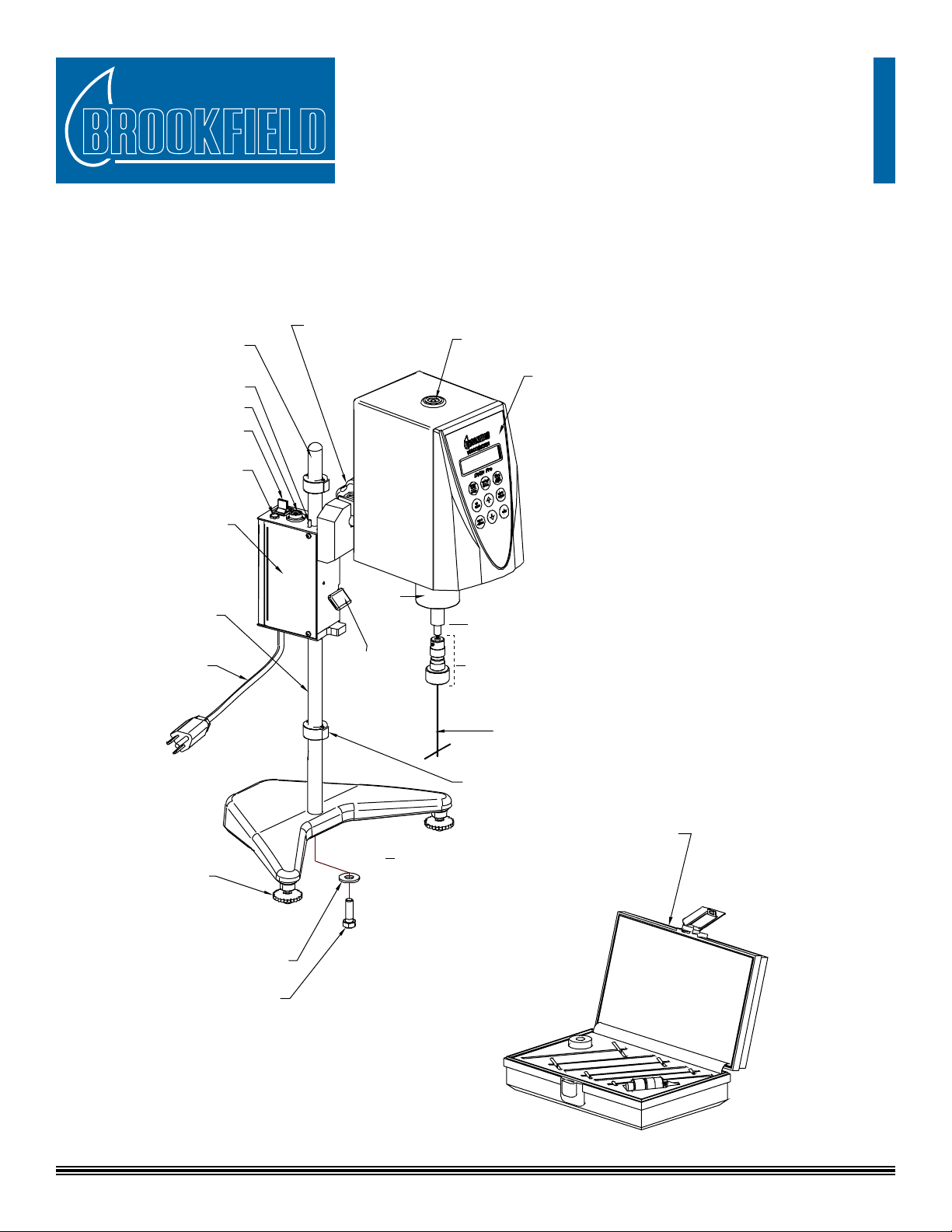
Model D Helipath Stand with EZ-Lock Coupling
EZ-Lock Makes it EZ to attach and remove spindles!
1. Slide sleeve up; 2. Insert Spindle; 3. Slide Sleeve Down
UPRIGHT ROD
(VS-38)
CLAMP KNOB
(VS-41Y )
BUBBLE LEVEL
VISCOMETER HEAD
with EZ-Lock
(not included with
Helipath Stand)
CHUCK, WEIGHT & CLOSER
ASSEMBLY, EZ LOCK (BTU-18KY)
T-BAR SPINDLE (T-A through T-F)
DISENGAGING
LEVER
PIVOT
CUP
ADJUSTABLE
STOP (2)
(HS-23Y)
BASE with LEVELING
SCREWS & BUMPER (VS-2SY)
SPINDLE SET
(SSTK)
Includes 6 T-Bar
Spindles T-A through
T-F, Chuck, Weight &
Closer Assembly with
EZ-Lock Spindle
Coupling & Case
REVERSING ROD
(Top & Bottom)
BUBBLE LEVEL
POWER SWITCH
POWER INDICATOR
LIGHT
DRIVE UNIT
(HS-1Y)
GEAR RACK
(REAR)
HELIPATH
POWER CORD
LEVELING
SCREWS (2)
(VS-3)
WASHER
SCREW
Assembly & Operating Instructions
Manual No. M09-103
Model D Helipath Stand Parts Identication
- 1 -
Page 2

Check carefully to see that all components are received with no concealed damage.
1 drive unit (HS-1Y) Spindle Set (SSTK) includes:
1 base (VS-2SY) • 6 T-bar spindles (T-A — T-F)
2 leveling screws (VS-3) • 1 chuck/closer/weight assembly (BTU-18KY)
1 upright rod (VS-38) • 1 spindle box (TU-25Y)
2 adjustable stops (HS-23Y)
Stand Assembly
Insert the upright rod in the base, positioning the gear rack facing toward the rear. Thread the screw with lock washer into rod under
the base, but do not tighten. Slide one adjustable stop down the upright rod, with locking plate facing up. With the drive unit handle
clamp facing forward, depress the disengaging lever and slide the drive unit down the upright rod. Slide the other adjustable stop down
the upright rod above the drive unit; again, locking plate of adjustable stop faces up. Center the complete assembly between the base
legs and tighten the screw into the upright rod. Install the clamp knob, but do not tighten.
Viscometer Mounting
Slide the Viscometer handle core into the handle clamp and tighten the clamp knob. Check the lateral position of the Viscometer relative
to the base. Make adjustments and retighten the screw as required to center the Viscometer between the base legs. Referring to the stand
bubble level, adjust the base leveling screws until the stand is level. Referring to the Viscometer bubble level, position the Viscometer
until the bubble is centered (right to left) and tighten the clamp knob.
CAUTION: Position power cords so they do not interfere with the travel of the drive unit.
Viscometer Operation
Note: If your viscometer was supplied with a guardleg, this guardleg is not used when using T-bar spindles. Remove it by
loosening the round thumbscrew on the back side of the pivot cup.
Refer to the Helipath Stand Spindle Ranges sheet and select a T-bar spindle. Take the chuck/weight/closer assembly, loosend the chuck,
slide the spindle into the chuck and tighten. Hold the EZ-Lock spindle coupling end of the chuck/weight/closer assembly with one hand
while gently raising the spring-loaded outer sleeve to its highest position with the other hand. Insert the EZ-Lock spindle coupling and
lower the sleeve. The sleeve should easily slide back down to hold the spindle/coupling assembly in place for use. Lower the spindle into
the uid by depressing the disengaging lever on the Helipath Drive Unit. Recommended initial spindle location is achieved when the
bottom of the T spindle is 1/4” above the surface of the test material. Push the reversing rod on the drive unit down. Make sure that the
drive unit is OFF (the yellow light on the top of the drive unit will not be illuminated).
Turn the Viscometer motor on and allow for one to two revolutions of the spindle before turning on the Helipath Drive Unit which, when
switched on, will travel 7/8” per minute in a downward direction. Set the adjustable stops to accommodate the travel of the Helipath
that will provide the desired penetration of the spindle (we recommend that the T-bar spindle penetrate no farther than 1/4” from the
bottom of the test material). Turn on the Helipath Drive Unit (the yellow light will now be illuminated). NOTE: Brookeld does not
recommend operating the Viscometer at RPMs greater than 12, when using the Helipath Stand Accessory.
Observe the dial reading or % torque display (on Digital Models). Make sure the torque reading remains above 10%. Record the viscosity
readings where necessary, keeping in mind that low rotational speeds may produce the best results. In this way, a viscosity value will be
obtained for the consistency of the material at equal increments of penetration through the material. Operation at low rotational speeds
will usually produce optimum readings. Multiple readings should be taken as the T-bar travels through the helical cycle.
Note: 1) It is recommended that the spindles be cleaned after each measurement.
2) The spindle can be placed anywhere in the sample material’s container prior to use, as long as rotation of the spindle is not
impeded.
3) It is not recommended to use T-Bar spindles to check calibration of your Viscometer. Use the standard spindles
which came with your Viscometer.
- 2 -
Page 3

Viscometer Range Data
Range Data* (T-Bar Spindles) - applicable to Dial Reading & Digital Viscometers/Rheometers
** DV-I+ / II+ /
DIAL READING DV-I/DV-II
LV 156 - 3120 156 - 3120 156 - 9360K 156 - 9360K
RV 2K - 20K 2K - 20K 2K - 100M 2K - 100M
HA 4K - 40M 4K - 40M 4K - 200M 4K - 200M
HB 16K - 160M 16K - 160M 16K - 800M 16K - 800M
* Ranges in centiPoise (cP) 1 cP = 1 mPa•s
** Maximum range shown is at 0.1 RPM
K = 1000
M = 1,000,000
DV-II+ Programmable
/ DV-II+ Pro
**DV-III / DV-III+ /
DV-III ULTRA
Spindle Range Data
This Universal Spindle Range table lists the Spindle Range Coefcients for all (6) T-bar spindles. Dividing the coefcient number
by any rotational speed will give the full scale viscosity range for a Viscometer/Rheometer spindle/speed combination. (The Auto
Range key on DV-E, DV-I+, DV-II+ or DV=III+ instruments provides this information in the digital display).
Spindle Range Coecient
Spindle Entry Code LV RV HA HB
T-A 91 18,750 200,000 400,000 1,600,000
T-B 92 37,440 400,000 800,000 3,200,000
T-C 93 93,600 1,000,000 2,000,000 8,000,000
T-D 94 187,200 2,000,000 4,000,000 16,000,000
T-E 95 468,000 5,000,000 10,000,000 40,000,000
T-F 96 936,000 10,000,000 20,000,000 80,000,000
(Analog/Dial Viscometer)
Example: 1) Determine the full scale viscosity range (100% of torque scale) of a T-C spindle running on a RV Series @ 5 RPM.
Full Scale Range = Spindle Coefcient = 1,000,000
Spindle Speed 5 RPM
1) Determine minimum viscosity range (10% of torque scale) at above conditions.
Min. Visc. Range = Full Scale Range = 200,000
10 10
Note: Maximum operable speed when using Helipath Stand is 10 or 12 RPM depending on speeds available on your
viscometer.
= 200,000 cP
= 20,000 cP
- 3 -
Page 4

Spindle Factors (for Analog/Dial Viscometers)
Speed
(RPM)
T-A or 91 T-B or 92 T-C or 93 T-D or 94 T-E or 95 T-F or 96
12 15.6 31.2 78 156 390 780
6 31.2 62.4 156 312 780 1.56K
3 62.4 124.8 312 624 1.56K 3.12K
1.5 124.8 249.6 624 1.248K 3.12K 6.24K
0.6 312 624 1.56K 3.12K 7.8K 15.6K
0.3 624 1.248K 3.12K 6.24K 15.6K 31.2K
SPINDLE NUMBER
RVT VISCOMETERS
LVT VISCOMETERS
Speed
(RPM)
T-A or 91 T-B or 92 T-C or 93 T-D or 94 T-E or 95 T-F or 96
10 200 400 1K 2K 5K 10K
5 400 800 2K 4K 10K 20K
4 500 1K 2.5K 5K 12.5K 25K
2.5 800 1.6K 4K 8K 20K 40K
2 1K 2K 5K 10K 25K 50K
1 2K 4K 10K 20K 50K 100K
0.5 4K 8K 20K 40K 100K 200K
SPINDLE NUMBER
Speed
(RPM)
T-A or 91 T-B or 92 T-C or 93 T-D or 94 T-E or 95 T-F or 96
10 400 800 2K 4K 10K 20K
5 800 1.6K 4K 8K 20K 40K
2.5 1.6K 3.2K 8K 16K 40K 80K
1 4K 8K 20K 40K 100K 200K
0.5 8K 16K 40K 80K 200K 400K
Speed
(RPM)
T-A or 91 T-B or 92 T-C or 93 T-D or 94 T-E or 95 T-F or 96
10 1.6K 3.2K 8K 16K 40K 80K
5 3.2K 6.4K 16K 32K 80K 160K
2.5 6.4K 12.8K 32K 34K 160K 320K
1 16K 32K 80K 160K 400K 800K
0.5 32K 64K 160K 320K 800K 1.6M
K = 1000 M = 1,000,000
To calculate viscosity in centipoise (cP), multiply the dial reading by the factor corresponding to the
viscometer spindle and speed combination utilized. 1cP = 1mPa•s
HAT VISCOMETERS
SPINDLE NUMBER
HBT VISCOMETERS
SPINDLE NUMBER
Crossbar Length
Spindle Inches mm
T-A 1.894 (48.1)
T-B 1.435 (36.4)
T-C 1.065 (27.1)
T-D 0.804 (20.4)
T-E 0.604 (15.3)
T-F 0.430 (10.9)
- 4 -
 Loading...