

Brookfield RVDV-II+Pro, LVDV-II+Pro, HBDV-II+Pro, HADV-II+Pro Operating Instructions Manual
Page 1

SPECIALISTS IN THE
MEAS UREMENT AN D
CONTROL OF VISCOSITY
TEL 508-946-6200
FAX 508-946-6262
or 800-628-8139 (USA e xcluding MA)
I
NTERNET
http://www.brookeldengineering.com
BROOKFIELD ENGINEERING LABORATORIES, INC.
11 Commerce Boulevard, M iddleboro, M A 02346 USA
with oces in :
Boston • Chicago • London • Stuttgart • Guangzhou
BROOKFIELD DV-II+Pro
Viscometer
Operating Instructions
Manual No. M/03-165 D0410
Brookeld Engineering Labs., Inc. Page 1 Manual No. M/03-165-D0410
Page 2

TABLE OF CONTENTS
I. INTRODUCTION ......................................................................................................................................... 4
I.1 Components ................................................................................................................................................................................... 5
I.2 Utilities ..............................................................................................................................................................................................7
I.3 Specications .................................................................................................................................................................................7
I.4 Installation .......................................................................................................................................................................................8
I.5 Safety Symbols and Precautions ............................................................................................................................................. 9
I.6 Key Functions ...............................................................................................................................................................................10
I.7 Cleaning .........................................................................................................................................................................................11
II. GETTING STARTED .................................................................................................................................. 12
II.1 Autozero .........................................................................................................................................................................................12
II.2 Spindle Selection .......................................................................................................................................................................13
II.3 Speed Selection, Setting, Running ......................................................................................................................................14
II.4 Display Selection ........................................................................................................................................................................15
II.5 Autorange ......................................................................................................................................................................................16
II.6 Out of Range .................................................................................................................................................................................
II.7 Temperature Display ..................................................................................................................................................................18
II.8 Printing ..........................................................................................................................................................................................19
II.9 External Control Mode ..............................................................................................................................................................
II.10 Making Viscosity Measurements ..........................................................................................................................................20
II.11 Time Modes for Viscosity Measurement ............................................................................................................................21
17
20
III. OPTIONS .................................................................................................................................................... 22
III.1 Introduction to OPTIONS .........................................................................................................................................................22
III.2 Setup ................................................................................................................................................................................................
III.2.1 Temperature Display ....................................................................................................................................................25
III.2.2 Units of Measurement ..................................................................................................................................................26
III.2.3 Motor Speed Set Selection .........................................................................................................................................
III.2.4 Printer Output Port ........................................................................................................................................................28
III.2.5 Data Averaging ...............................................................................................................................................................28
III.3 Time Modes....................................................................................................................................................................................29
III.3.1 Time to Stop .....................................................................................................................................................................29
III.3.2 Time to Torque .................................................................................................................................................................32
III.3.3 Print Time Interval ..........................................................................................................................................................34
III.3.4 PC Program (On/O ) .....................................................................................................................................................35
III.3.5 Download a Program ....................................................................................................................................................36
III.3.6 Run a Program .................................................................................................................................................................37
24
26
IV. DVLOADER SOFTWARE ........................................................................................................................ 39
IV.1 B.E.V.I.S. Overview .......................................................................................................................................................................39
IV.2 Description of B.E.V.I.S. Commands ......................................................................................................................................40
IV.3 Creating a B.E.V.I.S. Program ...................................................................................................................................................41
IV.4 Downloading a B.E.V.I.S. Program .........................................................................................................................................43
IV.5 Example Programs ......................................................................................................................................................................44
V. AUTOMATED DATA GATHERING & ANALYSIS .............................................................................. 46
V.1 WINGATHER32..............................................................................................................................................................................46
V.2 RHEOCALC32 ................................................................................................................................................................................48
Brookeld Engineering Labs., Inc. Page 2 Manual No. M/03-165-D0410
Page 3

Appendix A - Cone/Plate Viscometer Set-Up .....................................................................................................................50
Appendix B - Viscosity Ranges ...............................................................................................................................................55
Appendix C - Variables in Viscosity Measurements .........................................................................................................61
Appendix D - Spindle and Model Codes ..............................................................................................................................63
Appendix E - Calibration Procedures ....................................................................................................................................66
Appendix F - The Brookeld Guardleg .................................................................................................................................73
Appendix G - Speed Sets ...........................................................................................................................................................75
Appendix H - Communications ...............................................................................................................................................76
Appendix I - Model S Laboratory Stand .............................................................................................................................79
Appendix J - DVE-50A Probe Clip ..........................................................................................................................................81
Appendix K - Fault Diagnosis and Troubleshooting ........................................................................................................82
Appendix L - Instrument Dimensions .................................................................................................................................86
Appendix M - Warranty Repair and Service .........................................................................................................................87
Brookeld Engineering Labs., Inc. Page 3 Manual No. M/03-165-D0410
Page 4

I. INTRODUCTION
The Brookeld DV-II+Pro Viscometer measures uid viscosity at given shear rates. Viscosity
is a measure of a uid’s resistance to ow. You will nd a detailed description of the science of
viscosity in the Brookeld publication “More Solutions to Sticky Problems” a copy of which
was included with your DV-II+Pro.
The DV-II+Pro offers exceptional versatility in modes of control allowing for traditional
standalone operation, automatic operation through programs downloaded from the PC or with
complete control by PC using Brookeld Rheocalc32 Software.
• The DV-II+Pro can be used as a traditional Brookeld viscometer for collection of single
speed viscosity data through the easy to use keypad; just select the spindle and speed and
read the value from the display. [see Section II, Getting Started]
• The Brookeld DVLoader Software can be used to program the DV-II+Pro to control
all aspects of the test and data collection without the need for the operator to monitor the
instrument; just start the program and return to the printed test data (printer is optional).
[see Section IV, DVLoader Software]
• The Brookeld Rheocalc32 Software will perform all control and data collection func
tions of the DV-II+Pro from the PC while also providing a platform for advanced data
collection and analysis. [see Section II.9, External Control]
In any of these modes of control, the DV-II+Pro will provide the best in viscosity measurement
and control.
-
The principal of operation of the DV-II+Pro is to drive a spindle (which is immersed in the
test uid) through a calibrated spring. The viscous drag of the uid against the spindle is
measured by the spring deection. Spring deection is measured with a rotary transducer. The
measurement range of a DV-II+Pro (in centipoise or milliPascal seconds) is determined by the
rotational speed of the spindle, the size and shape of the spindle, the container the spindle is
rotating in, and the full scale torque of the calibrated spring.
There are four basic spring torque series offered by Brookeld:
Spring Torque
Model dyne/cm milli Newton/m
LVDV-II+Pro 673.7 0.0673
RVDV-II+Pro 7,187.0 0.7187
HADV-II+Pro 14,374.0 1.4374
HBDV-II+Pro 57,496.0 5.7496
The higher the torque calibration, the higher the measurement range. The measurement range
for each torque calibration may be found in Appendix B.
All units of measurement are displayed according to either the CGS system or the SI system.
1. Viscosity appears in units of centipoise (shown as “cP”) or milliPascal-seconds (shown as
“mPa•s”) on the DV-II+Pro Viscometer display.
2. Shear Stress appears in units of dynes/square centimeter (“D/cm
meter (“N/m
2
”).
2
”) or Newtons/square
3. Shear Rate appears in units of reciprocal seconds (“1/SEC”).
4. Torque appears in units of dyne-centimeters or Newton-meters (shown as percent “%” in
both cases) on the DV-II+Pro Viscometer display.
Note: To change CGS to SI units on the display - see Section III.2.2.
Brookeld Engineering Labs., Inc. Page 4 Manual No. M/03-165-D0410
Page 5

The equivalent units of measurement in the SI system are calculated using the following
conversions:
SI CGS
Viscosity: 1 mPa•s = 1 cP
2
Shear Stress: 1 Newton/m
= 10 dyne/cm
Torque: 1 Newton/m = 10
7
dyne/cm
2
References to viscosity throughout this manual are done in CGS units. The DV-II+Pro
Viscometer provides equivalent information in SI units.
I.1 Components
Please check to be sure that you have received all components, and that there is no damage. If
you are missing any parts, please notify Brookeld Engineering or your local Brookeld agent
immediately. Any shipping damage must be reported to the carrier.
Component Part Number Quantity
DV-II+Pro Viscometer varies 1
Model S Laboratory Stand MODEL S 1
Spindle Set with Case varies 1
LVDV-II+Pro set of four spindles SSL or
RVDV-II+Pro set of six spindles (#2 - #7) SSR or
HA/HBDV-II+Pro set of six spindles (#2 - #7) SSH
For Cone/Plate versions: a spindle wrench, one cone spindle and sample cup,
Part No. CPE-44Y replace the spindle set.
Power Cord 1
DVP-65 for 115 or DVP-65
DVP-66 for 230 DVP-66
RTD Temperature Probe DVP-94Y 1
Guard Leg: 1
LVDV-II+Pro B-20Y
RVDV-II+Pro B-21Y
Carrying Case DVE-7Y 1
DVLOADER CD ROM DVLOADER 1
Cable (DV-II+Pro to computer) DVP-80 1
Operating Manual M/03-165 1
Brookeld Engineering Labs., Inc. Page 5 Manual No. M/03-165-D0410
Page 6
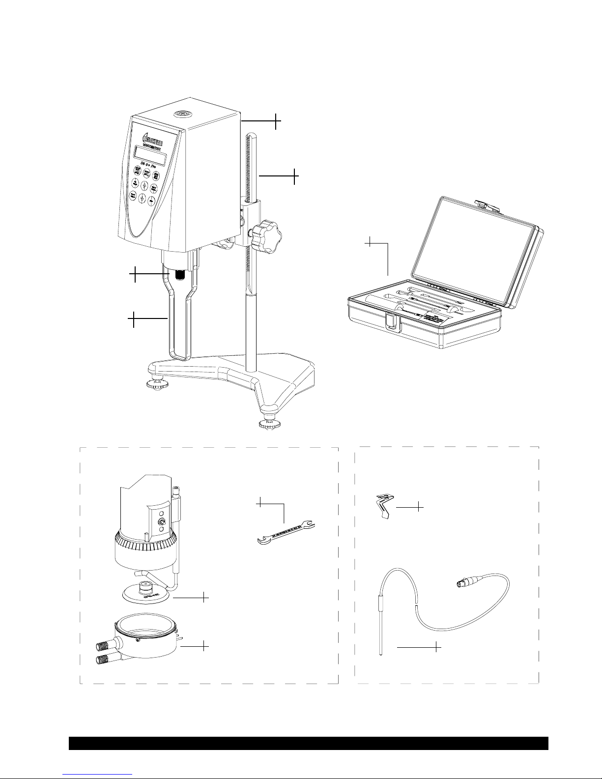
COMPONENT DIAGRAM
Cone/Plate Optio
n
Temperature Probe Optio
n
Spindle Set
Cone Spindle
Wrench
Sample Cup
Temperature Probe Clip
Temperature Probe
Shipping
Cap
DV-II Pro
Viscometer
Model S
Laboratory Stand
Guard Leg
LV Spindle Set
shown above
Brookeld Engineering Labs., Inc. Page 6 Manual No. M/03-165-D0410
Page 7

I.2 Utilities
Input Voltage: 115 VAC or 230 VAC
Input Frequency: 50/60 Hz
Power Consumption: 30 VA
Power Cord Color Code:
United States Outside United States
Hot (live) Black Brown
Neutral White Blue
Ground (earth) Green Green/Yellow
Main supply voltage uctuations are not to exceed ±10% of the nominal supply voltage.
I.3 Specications
Speeds: Choice of 3 options.
Instrument has “Interleaved” speeds when manufactured.
Standalone Interleaved: LV/RV (18 speeds) 8 LV speeds followed by
Sequential: LV/RV (18 speeds) 8 LV speeds and 10 RV
Custom: 54 speeds, user selectable
10 RV speeds
speeds arranged in sequential order from
lowest 0.3 rpm to highest 100 rpm.
External (PC Control) .01 - 200 rpm
0.01 rpm increments from 0.01 to 0.99 rpm
0.1 rpm increments from 1.0 to 200 rpm
Note: Refer to Appendix G for detailed list of all speeds.
Weight: Gross Weight 23 lbs. 10.5 kg.
Net Weight 20 lbs. 9 kg.
Carton Volume 1.65 cu. ft. 0.05 m
Temperature Sensing Range: -100˚C to 300˚C (-148˚F to 572˚F)
Analog Torque Output: 0 - 1 Volt DC (0 - 100% Torque)
Analog Temperature Output: 0 - 3.75 Volts DC (-100°C to +275°C)
RS232 Compatible Serial Port for use with an attached printer or PC.
Centronics Compatible Parallel Port for use with an attached printer.
Viscosity Accuracy: ±1.0% of full scale range
3
The use of accessory items will have an effect on the
measurement accuracy. See Appendix B.
Viscosity Repeatability: ±0.2%
Brookeld Engineering Labs., Inc. Page 7 Manual No. M/03-165-D0410
Page 8

Temperature Accuracy: ±1°C | -100°C to +149°C
±2°C | +150°C to +300°C
Operating Environment: 0°C to 40°C temperature range (32°F to 104°F)
20% - 80%R.H.: non-condensing atmosphere
Ball Bearing Option:
If you ordered the ball bearing suspension system with your new instrument please
note the following:
1) The ball bearing suspension in your Brookeld instrument is noted on the serial tag
on the back of the head by the letter “B” after the mode.
2) When attaching and detaching the spindle, it is not necessary to lift the coupling
where the spindle connects to the instrument.
3) The Oscillation Check explained in the Appendix under Fault Diagnosis and
Troubleshooting does not pertain to this instrument.
Electrical Certications:
Conforms to CE Standards:
BSEN 61326: Electrical equipment for measurement, control and laboratory use -
EMC requirements
BSEN 61010-1: Safety requirements for electrical equipment, for measurement, control
and laboratory use
Notice to customers:
This symbol indicates that this product is to be recycled at an appropriate collection center.
Users within the European Union:
Please contact your dealer or the local authorities in charge of waste management on how to
dispose of this product properly. All Brookeld ofces and our network of representatives and
dealers can be found on our website: www.brookeldengineering.com
Users outside of the European Union:
Please dispose of this product according to your local laws.
I.4 Installation
Note: “IQ, OQ, PQ”, a guideline document for installation, operation and performance validation
for your DV-II+Pro digital viscometer can be downloaded from our web site www.
brookeldengineering.com.
1) Assemble the Model S Laboratory Stand (refer to assembly instructions in Appendix I).
Brookeld Engineering Labs., Inc. Page 8 Manual No. M/03-165-D0410
Page 9
2) Put the viscometer on the stand.
3) Connect the RTD probe to the socket on the rear panel of the DV-II
+Pro.
4) The Viscometer must be leveled. The level is adjusted using the two leveling screws on
the base. Adjust so that the bubble level on top of the DV-II+Pro is centered within the
circle.
Note: Check level periodically during use.
5) Remove the white shipping cap which secures lower coupling nut on Viscometer to pivot
cup.
6) Make sure that the AC power switch at the rear of the DV-II
+Pro is in the OFF position.
Connect the power cord to the socket on the back panel of the instrument and plug it into
the appropriate AC line.
The AC input voltage and frequency must be within the appropriate range as shown
on the nameplate of the viscometer.
Note: The DV-II+Pro must be earth grounded to ensure against electronic failure!!
7) Turn the power switch to the ON position and allow to warm up for 10 minutes before
performing autozero.
8) For Cone/Plate models, refer to Appendix A.
9) If appropriate, connect interconnecting cable (DVP-80) to serial port for connection of
DV-II+Pro to PC or printer.
10) If appropriate, connect interconnecting cable to parallel port for connection of DV-II+Pro
to printer.
11) If appropriate, connect interconnecting cable (DVP-96Y) to analog (serial) port for con
nection of DV-II+Pro to chart recorder.
I.5 Safety Symbols and Precautions
Safety Symbols
The following explains safety symbols which may be found in this operating manual.
Indicates hazardous voltages may be present.
Refer to the manual for specic warning or caution information to avoid personal
injury or damage to the instrument.
Precautions
If this instrument is used in a manner not specied by the manufacturer, the
protection provided by the instrument may be impaired.
-
This instrument is not intended for use in a potentially hazardous environment.
Brookeld Engineering Labs., Inc. Page 9 Manual No. M/03-165-D0410
Page 10
In case of emergency, turn off the instrument and then disconnect the electrical
DV- II+ P ro
VI SC OME TE R
B ROOKFIELD
PRINT
SELEC T
SPIND LE
SELEC T
DISPL AY
SET
SPEED
ENTER
AUTO
RANGE
MOTOR
ON/OF F
ESCAP E
£
§
OPTIO NS
TAB
ô
ö
cord from the wall outlet.
The user should ensure that the substances placed under test do not release
poisonous, toxic or ammable gases at the temperatures which they are subjected
to during the testing.
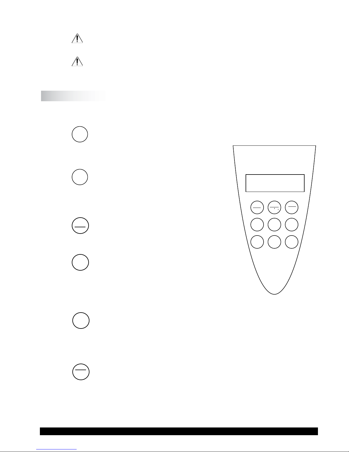
I.6 Key Functions
Figure I-1 shows the control keys on the face of the DV-II+Pro Viscometer. The
following describes the function of each key.
£
This key is used to scroll UP (in an increasing
UP ARROW
value direction) through the available speed,
spindle and Option menu tables.
§
This key is used to scroll DOWN (in a
DOWN ARROW
decreasing value direction) through the
available speed, spindle and option menu
tables.
MOTOR
ON/OFF
MOTOR ON/OFF/ESCAPE
ESCAPE
Turns the motor ON or OFF. ESCAPE exits the
Options menu.
SET
SPEED
Causes the DV-II+Pro to begin running at the
SET SPEED
currently selected speed. This function works
only when the motor is ON. Also used to select
custom speeds when in the Custom Speed
option.
Figure I-1
Selects the data parameter to be displayed:
SELECT
SELECT DISPLAY
DISPLAY
cP Viscosity (cP or mPa•s)
SS Shear Stress (dynes/cm2 or Newtons/m2)
ENTER
AUTO
ENTER/AUTO RANGE
RANGE
SR Shear Rate (1/sec)
ENTER: Used to execute the currently ashing option.
AUTO RANGE: Presents the maximum (100% torque) viscosity attainable using the
Brookeld Engineering Labs., Inc. Page 10 Manual No. M/03-165-D0410
selected spindle at the current viscometer spindle speed.
Page 11
SELECT
SPINDLE
SELECT SPINDLE
Initiates spindle selection on the rst press and then selects the currently scrolled-to
spindle when pressed a second time.
Selects printing and non-printing modes when a printer is attached.
OPTIONS: Presents the Options menu, ashing the last escaped option.
PRINT
OPTION
TAB
PRINT
OPTIONS/TAB
F
TAB: Toggles between selectable items when indicated, as shown in
Figure I-2.
Note: Symbol indicating
the OPTIONS/TAB key
f
°F(FAHRENHEIT) $
g
f
CGS UNITS #
g
Figure I-2
Note: Inverted text (black background with white lettering) indicates that the
information is ashing on the viscometer display.
I.7 Cleaning
Be sure to remove the spindle from the instrument prior to cleaning. Severe instrument
damage may result if the spindle is cleaned in place.
Instrument and Keypad: Clean with a dry, non-abrasive cloth. Do not use solvents
or cleaners.
Immersed Components (spindles): Spindles are made of stainless steel. Clean with a non-
abrasive cloth and solvent appropriate for sample mate-
rial.
Note: When cleaning, take care not to apply excessive force - it may bend the
spindles.
Brookeld Engineering Labs., Inc. Page 11 Manual No. M/03-165-D0410
Page 12

II. GETTING STARTED
II.1 Autozero
Before readings may be taken, the Viscometer must be Autozeroed. This action is performed
each time the power switch is turned on. (Note: If cable DVP-80 is connected for printer or
computer communication see section II.9). The display window on the Viscometer will guide
you through the procedure as follows:
Turn the power switch (located on the rear panel) to the ON position. This will result in
the screen display shown in Figure II-1 indicating that the DV-II+Pro viscometer is in the
standalone mode (is not connected to a computer).
BROOKFIELD DV-2+
PRO VISCOMETER
Figure II-1
After a few seconds, the following screen appears indicating the version of the operating
rmware (the built in program which controls the instrument) and a two-digit alphanumeric
code which indicates the Model number (see Table D2 in Appendix D; the code tells the spring
torque rating or the viscosity measurement range of your viscometer). For most DV-II+Pro
Viscometers, this information will be either “LV”, “RV” or “HB”:
BROOKFIELD DV-2+
RV V6.3
Figure II-2
No key press is required at this point. After a short time, the display will clear and the
following will be displayed:
REMOVE SPINDLE
PRESS ANY KEY
Figure II-3
After removing the spindle and pressing any key, the DV-II+Pro begins its Autozero. The
screen will ash “Autozeroing.”
After approximately 15 seconds, the display shows the screen in Figure II-4:
REPLACE SPINDLE
PRESS ANY KEY
Brookeld Engineering Labs., Inc. Page 12 Manual No. M/03-165-D0410
Figure II-4
Page 13

Pressing any key at this point results in the display of the DV-II+Pro default screen:
CP 0.0 20.1C
OFFRPM % 0.0
Figure II-5
The display will vary depending upon the selection of temperature (°F or °C) and units of viscosity
(cP or mPa•s).
II.2
SELECT
Spindle Selection
SPINDLE
LVDV-II+Pro Viscometers are provided with a set of four spindles and a narrow guardleg;
RVDV-II+Pro Viscometers come with a set of six spindles and a wider guardleg; HADVII+Pro and HBDV-II+Pro Viscometers come with a set of six spindles and no guardleg. (See
Appendix F for more information on the guardleg.)
The spindles are attached to the viscometer by screwing them onto the lower shaft. Note that
the spindles have a left-hand thread. The lower shaft should be secured and slightly lifted with
one hand while screwing the spindle to the left. The face of the spindle nut and the matching
surface on the lower shaft should be smooth and clean to prevent eccentric rotation of the
spindle. Spindles can be identied by the number on the side of the spindle coupling nut.
The DV-II+Pro must have a Spindle Entry Code number to calculate Viscosity, Shear Rate and
Shear Stress values. The DV-II+Pro memory contains parameters for all standard Brookeld
spindles including custom spindles and the two digit entry code for each spindle (the complete
list of entry codes may be found in Appendix D).
Note: The DV-II+Pro will remember the Spindle Entry Code which was in use when the
power was turned off.
Pressing the SELECT SPINDLE key will temporarily display the current selected spindle
code in place of temperature and cause the character S to begin to blink . It will blink for
about three seconds. If the UP or DOWN ARROW keys are pressed (while S is blinking) the
two character spindle value to the right of the S character will begin to change (in either an
increasing or decreasing direction depending upon which ARROW key is pressed) for each
press of the key. If the ARROW key is pressed and held, the display will scroll through the
spindle codes for as long as the ARROW key is depressed. When it reaches the last item in the
list (either at the top or bottom of the list) the spindle code displayed will “roll-over” to either
the rst or last spindle code and the scroll action will continue.
When the desired spindle code is displayed, release the ARROW key to halt further scrolling.
Press the SELECT SPINDLE key once again. This will cause the S character to cease blinking
and the new spindle code will be accepted for use in viscometer calculations. After 3 seconds
the current spindle code will be replaced by the temperature display.
Note: You have approximately three seconds in which to press the SELECT SPINDLE
key before the blinking stops. If you fail to press the SELECT SPINDLE key before
the blinking stops you will have to repeat the above steps and re-select the desired
spindle.
Brookeld Engineering Labs., Inc. Page 13 Manual No. M/03-165-D0410
Page 14
The DV-II+Pro will begin to calculate using the new spindle parameters as soon as the SELECT
SPINDLE key is pressed the second time.
Note: The number 99 spindle is for use with special spindles when using Brookeld’s
RHEOCALC32 computer program. Refer to the RHEOCALC32 operator manual
for further information on using “99” spindles.
The DV-II+Pro may also be programmed at Brookeld Engineering for “special” user spindles.
These “special” spindles will appear on the spindle scroll list starting with designation “AA”
and continuing through “AZ”. Contact Brookeld Engineering regarding your needs for
special spindles.
II.3
SET
Speed Selection, Setting, Running
SPEED
There are 54 speeds programmed into the DV-II+Pro. These speeds correspond to the standard
LVT, RVT, HAT and HBT dial models (18 possible speeds altogether) plus 36 additional
speeds.
The DV-II+Pro comes with the Sequential Speed Set already selected (see Appendix G). The
speed set will start at speed 0.0. It will then scroll up through the LV speeds, pass through
speed 0.0 again, and then scroll up through the RV speeds, pass through speed 0.0 again and
then repeat the above sequence.
The DV-II+Pro can also be congured by the operator to interleave the LV and RV speeds. See
Section III.2.3 on Setup for a description of how to install the Interleave Speed Set.
A complete list of speed sets and custom speeds is included in Appendix G. The DV-II+Pro
can be programmed to select up to 19 of the 54 speeds for use at any one time. Speed 0.0 is the
20th speed and is automatically included. See Section III. 2.3.2 on Setup for a description of
how to install a Custom Speed Set.
To select a Viscometer speed rst press either the UP or DOWN arrow keys which will cause
the area to the right of RPM to display the currently selected speed. Figure II-6 shows the DVII+Pro is operating at 6.0 RPM, and the current selected speed is 6.0 RPM.
If the ARROW key is pressed just once and then released, the characters “RPM” will blink for
three seconds, then will cease blinking resulting in no change to the speed entry.
Note: The speed selection process remembers the last value of scrolled-to speed so that the
next time you initiate a speed change (by pressing an ARROW key), the DV-II+Pro
will begin its scroll display from the last entered value.
The last-scrolled-to speed does not necessarily have to be the same as the speed at which the
DV-II+Pro is currently running. The user may operate at a given speed and pre-set the DVII+Pro to the next desired speed before that speed will be used. For example, if the DV-II+Pro
is currently running at 6.0 RPM and was previously scrolled to 12 RPM, a single press of either
Brookeld Engineering Labs., Inc. Page 14 Manual No. M/03-165-D0410
CP 123.4 20.1C
6.0RPM6.0 % 15.6
Figure II-6
Page 15

ARROW key would result in the Figure II-7 screen display:
cP 123.4 20.1C
6.0RPM12 % 15.6
Figure II-7
Pressing the SET SPEED key would cause the DV-II+Pro to begin running at 12 RPM.
If the user did not press the SET SPEED key, the DV-II+Pro would continue to run at its
current speed of 6 RPM. In fact, you may scroll to a new speed (12 RPM in this example) and
press the SET SPEED key at any future time (without further pressing an ARROW key) to
immediately cause the DV-II+Pro to run at the new speed. Pressing the ARROW key at any
time reminds the operator of what was selected for the next speed.
If an ARROW key is pressed and held the DV-II+Pro will scroll up (or down) through the
speed table. When it reaches the last speed in the list (either at the top or bottom of the list) the
speed displayed will “roll-over” to either the rst or last speed in the table and the scroll action
will continue.
When the required speed is displayed, release the ARROW key to halt further scrolling. You
have approximately two seconds (before the blinking RPM stops) in which to press the SET
SPEED key to immediately begin rotation at the new speed.
Pressing the MOTOR ON/OFF/ESCAPE key stops the Viscometer spindle rotation. Pressing
this key sets the DV-II+Pro to 0.0 RPM and causes the screen display to change as shown in
Figure II-8:
cP 0.0 20.1C
OFFRPM % 0.0
Figure II-8
Pressing the MOTOR ON/OFF/ESCAPE key again immediately starts the DV-II+Pro running
at the last scrolled-to-speed. If you had been running at 12 RPM, pressed MOTOR ON/OFF/
ESCAPE and then re-started the DV-II+Pro by pressing MOTOR ON/OFF/ESCAPE once
again, you would again be running at 12 RPM. However, if while the motor was off you had
scrolled to a new speed of 0.5 RPM, pressing the MOTOR ON/OFF/ESCAPE key would start
the DV-II+Pro running at 0.5 RPM.
Note: During both spindle or speed selection and scrolling operations, the DV-II+Pro
will continue to calculate and display Viscometer data as selected.
II.4
SELECT
Display Selection
DISPLAY
Viscosity (displayed in units of cP or mPa•s), Shear Stress and Shear Rate are displayed on the left
side of the top line. You may “step” through the three display options by pressing the SELECT DISPLAY
key. For example, the DV-II+Pro is currently displaying Viscosity in Figure II-9:
Brookeld Engineering Labs., Inc. Page 15 Manual No. M/03-165-D0410
Page 16
cP 123e3 20.1C
6.0RPM % 15.6
Figure II-9
If the viscosity value exceeds 99,999 scientic notation is used. In Figure II-9, the viscosity
value is 123,000 cP.
The rst press of the SELECT DISPLAY key would display Shear Stress (SS) in Dynes/cm2
(or Newtons/m2), see Figure II-10:
SS 29.0 20.1C
6.0RPM % 15.6
Figure II-10
If the shear stress value exceeds 99,999, scientic notation is used.
The next press of the SELECT DISPLAY key would display Shear Rate (SR) in 1/Sec (Figure
II-11).
SR 40.0 20.1C
6.0RPM % 15.6
Figure II-11
One more press of the SELECT DISPLAY key would result in a return to the viscosity screen,
as shown in Figure II-9.
Notes:
1. You may step through the display at any time. This will not interrupt any Viscometer
calculations that are in progress.
2. Display of shear rate and shear stress requires selection of appropriate spindles.
Otherwise, values displayed will be zero (0).
Units of Measurement
The DV-II+Pro Viscometer can be congured using the SETUP option (Section III.2.2) to
display/print in either the CGS or SI system of units.
ENTER
AUTO
RANGE
Autorange
II.5
The ENTER/AUTO RANGE key functions as auto range and allows you to determine the maximum
calculated viscosity (full scale reading) possible with the current spindle/speed setting only when
in the default screen. Pressing the key at any time will cause the current viscosity display to
change and show that maximum viscosity. The screen area displaying % (torque) will now display
a ashing “%100.0” to indicate this special condition. This maximum viscosity and ashing
Brookeld Engineering Labs., Inc. Page 16 Manual No. M/03-165-D0410
Page 17

%100.0 value will be displayed for as long as the ENTER/AUTO RANGE key is depressed. Figure II-12
shows the AUTO RANGE function for the situation where the No. 1 LV spindle is rotating at 60 rpm.
The full scale range is 100.0 cP (or 100.0 mPa
.
s).
cP 100.0 S61
60 RPM % 100
Figure II-12
Notes:
1. If the RPM is 0.0, the maximum viscosity displayed will be 0.0 cP (or 0.0 mPa.s).
2. While the Viscometer is in the Auto Range mode, any data sent to an attached printer
or computer reects the displayed values (i.e. Auto Range values).
3. This function is only available when in the default screen.
II.6 Out of Range
The DV-II+Pro gives indications for out-of-range operation. When % (Torque) readings exceed
100% (over-range), the display changes to that shown in Figure II-13; EEEE will also appear in
the display for % and viscosity or shear stress:
cP EEEE 20.1C
10 RPM % EEEE
Figure II-13
You must change either speed or spindle to correct this condition. If you operate at spindle
speeds that produce % (Torque) below 10.0 %, the DV-II+Pro ashes the % (Torque), cP
(Viscosity), SS (Shear Stress) and SR (Shear Rate) as shown in Figure II-14:
cP 12.4 20.1C
10 RPM % 8.2
Figure II-14
Negative % (Torque) will be displayed as shown in Figure II-15:
cP ---- 20.1C
10 RPM % -2.2
Figure II-15
Brookeld Engineering Labs., Inc. Page 17 Manual No. M/03-165-D0410
Page 18

Figure II-16 is an example of the printed output of each of the above conditions.
Normal Operation:
RPM=50 M=RV S=29 %=51.4 cP=10280 D/CM2=1285 1/SEC=12.3 T=20.1C Z00:30
Over-Range Operation (>100% torque) (see Fig. 15):
RPM=50 M=RV S=29 %=EEEE cP=EEEE D/CM2=EEEE 1/SEC=12.3 T=20.1C Z00:30
Under-Range Operation (<10% torque) (see Fig. 16):
?RPM=50 M=RV S=29 %=5.2 cP=1040 D/CM2=130 1/SEC=12.3 T=20.1C Z00:30
Negative Torque Operation (see Fig. 17):
RPM=50 M=RV S=29 %=-0.1 cP=---- D/CM2=---- 1/SEC=12.3 T=20.1C Z00:30
M = Torque Range T = Temperature Z = Time
Figure II-16
II.7 Temperature Display
The DV-II+Pro displays the temperature measured by its RTD temperature probe. Temperature
may be displayed in either ˚C (Centigrade) or ˚F (Fahrenheit) units, depending upon selection from
the Options menu. As received, the default temperature display will be in ˚C (Centigrade) units as
shown in the Figure II-17:
CP 123.4 20.1C
10 RPM % 19.7
Figure II-17
If you turn on the DV-II+Pro with the temperature probe disconnected, or remove the temperature
probe at any point after power-up, the display will indicate “- - - -C”. The four “dashes” indicate
the absence of the probe. If you were displaying temperature in Fahrenheit units the C would be
replaced by an F. Accuracy of temperature measurement for the DV-II+Pro is shown in Table 1.
Table 1
Temperature Accuracies for
DV-II+Pro Viscometer
Temperature Range Temperature Accuracy
-100°C to +149°C ±1.0°C
Brookeld Engineering Labs., Inc. Page 18 Manual No. M/03-165-D0410
+150°C to +300°C ±2.0°C
Page 19
II.8
For the case of CGS units with non-exponential results:
and CGS units with exponential results.
Similarly, for SI units with non-exponential results.
and SI units with exponential results.
M = Torque T = Temperature Z = Time
1 10 20 30 40 50 60 70 80
RPM=XXX M=XXXXX S=XX %=XXX.X cP=XXXXX D/CM2=XXXXX 1/SEC=XXXXX T=XX.XC ZXX=XX
RPM=XXX M=XXXXX S=XX %=XXX.X cP=XXXeX D/CM2=XXXeX 1/SEC=XXXXX T=XX.XC ZXX=XX
1 10 20 30 40 50 60 70 80
RPM=XXX M=XXXXX S=XX %=XXX.X mPas=XXXXX N/M2=XXXXX 1/SEC=XXXXX T=XX.XC ZXX=XX
1 10 20 30 40 50 60 70 80
1 10 20 30 40 50 60 70 80
RPM=XXX M=XXXXX S=XX %=XXX.X mPas=XXXeX N/M2=XXXeX 1/SEC=XXXXX T=XX.XC ZXX=XX
PRINT
Printing
The DV-II
+Pro will print data to an attached Serial (RS232) or Parallel (centronics) printer. The
printer must be attached to the appropriate rear panel output connector. See Appendix G for
conguration and connection requirements.
Data may be printed in two ways:
1. Pressing the
PRINT key once (for less than three (3) seconds) will result in the printing of one
standard print line.
2. If the
PRINT key is pressed and held for more than three (3) seconds, the DV-II+Pro will then
begin continuous printer output at a print rate interval selected via the Options menu (see
Section III.4). The display will show a ashing P in front of the % sign. See Figure II-18.
cP 123.4 20.1C
10 RPM P% 19.7
Figure II-18
To stop continuous printing, press the PRINT key for one (1) second. The ashing P will
disappear on the viscometer display.
Figure II-19 is an example of the print strings for CGS and SI units.
When printing via the parallel port, please note that if a printer is not attached to the viscometer,
the following screen appears:
Brookeld Engineering Labs., Inc. Page 19 Manual No. M/03-165-D0410
Figure II-19
PRINTERERROR
CHECKCONNECTION
Figure II-20
Page 20

II.9 External Control Mode
The DV-II+Pro Viscometer can be used in conjunction with Brookeld software, Rheocalc32
(V2.4 or higher). Through Rheocalc32, all viscometer functions are controlled by the computer.
The DV-II+Pro must be set to the external control mode to allow for proper communication with
Rheocalc32. To congure the external control mode, connect cable DVP-80 to the serial port on
the DV-II+Pro before turning on the DV-II+Pro. With the DVP-80 cable in place, the DV-II+Pro
will present the screen shown in Figure II-21 when it is turned on. If external control is selected,
the DV-II+Pro will display Figure II-22 and only accept control commands from Rheocalc32
software.
hEXTERNAL MODE
iSTANDALONE MODE
Figure II-21
V6.3 RV
EXTERNAL MODE
Figure II-22
The DV-II+Pro may be set to stand alone mode by turning it OFF and ON again and selecting
“Stand Alone” or by removing the DVP-80 cable prior to turning the DV-II+Pro on.
Note: The DV-II+Pro cannot communicate with DVLOADER software in the external
control mode. Choose “Stand Alone” when presented with Figure II-21 if you
want to use DVLOADER.
For information on controlling the DV-II+Pro from Rheocalc32 software, check the HELP
menu within Rheocalc32.
II.10 Making Viscosity Measurements
The following general procedure is used for making viscosity measurements. Brookeld
recommends the use of a 600 ml Low Form Grifn beaker (Brookeld Part No. BKR-600ml)
when using LV/RV/HA/HB spindles.
1. Mount the guardleg on the DV-II+Pro
Viscometer (LV and RV series) and insert into the
container.
2. Insert and center spindle in the test material until the uid’s level is at the immersion groove
on the spindle’s shaft. With a disc-type spindle, it is necessary to tilt the spindle slightly while
immersing to avoid trapping air bubbles on its surface. Attach the spindle to the lower shaft
of the viscometer. Lift the shaft slightly, holding it rmly with one hand while screwing the
spindle on with the other (note left-hand thread). Avoid putting side thrust on the shaft. Verify
the proper spindle immersion depth and that the viscometer is level.
Brookeld Engineering Labs., Inc. Page 20 Manual No. M/03-165-D0410
Page 21

3. The process of selecting a spindle and speed for an unknown uid is normally trial and error. An
appropriate selection will result in measurements made between 10-100 on the instrument
% torque scale.
Two general rules will help in the trial and error process.
1) Viscosity range is inversely proportional to the size of the spindle.
2) Viscosity range is inversely proportional to the rotational speed.
To measure high viscosity, choose a small spindle and/or a slow speed. If the chosen spindle/
speed results in a reading above 100%, then reduce the speed or choose a smaller spindle.
Experimentation may reveal that several spindle/speed combinations will produce satisfac
tory results between 10-100%. When this circumstance occurs, any of the spindles may be
selected.
Non-Newtonian uid behavior can result in the measured viscosity changing if the spindle
and/or speed is changed. See our publication, “More Solutions to Sticky Problems,” for more
detail.
Turn on motor.
Allow time for the indicated reading to stabilize. The time required for stabilization will depend
on the speed at which the Viscometer is running and the characteristics of the sample uid. For
maximum accuracy, readings below 10% should be avoided.
Record values.
4. Press the
MOTOR ON/OFF/ESCAPE key and turn the motor “OFF” when changing a spindle or
changing samples. Remove spindle before cleaning.
5. Interpretation of results and the instrument’s use with non-Newtonian and thixotropic materials
is discussed in the booklet, “More Solutions to Sticky Problems”, and in Appendix C, Variables
in Viscosity Measurements.
II.11 Time Modes for Viscosity Measurement
-
The Time Modes
allow the viscometer user to implement the unattended Time to Stop and Time to
Torque capabilities of the DV-II+Pro Viscometer. These features will allow the user to set up the
viscometer (i.e. select spindle and speed) and then record readings for a xed period of time (Time
to Stop) or until a set torque value is attained (Time to Torque). When timing begins, a message will
be displayed showing time remaining (or time elapsed) and the appropriate display item (viscosity
or torque) will be updated continuously during the event. Upon completion, the viscometer will
stop and display a screen stating that the test is complete and will also display the nal recorded
value for the viscosity in the rst case, or the time in minutes and seconds to reach the torque limit
in the second case. Pressing the UP or DOWN ARROW keys will allow additional viscometer data to
be examined. Pressing any other key (except the PRINT or ENTER/AUTORANGE key) will bring the user
back to the default (normal) viscometer display with the motor OFF. Refer to the Time Modes in
Section III.3.
Brookeld Engineering Labs., Inc. Page 21 Manual No. M/03-165-D0410
Page 22

III. OPTIONS
III.1
OPTION
TAB
Introduction to OPTIONS
F
The OPTIONS/TAB key provides access to the conguration (Setup) of the DV-II+Pro Viscometer as
well as special functions that can enhance the user’s ability to make viscosity measurements.
The Options menu, shown in Table 1, gives a complete picture of the various conguration
choices and special functions.
Quick References to Options
Table 2
Options Menu
SETUP:
Temperature — °F or °C
Units — CGS or SI
* Speed Sets — Sequential, Interleave, Custom
Printer Port — Serial (RS232) or Parallel
Data Averaging — Display Only
*
TIME TO STOP
* TIME TO TORQUE
SET PRINT TIME:
Set the Printing Time
PC PROG (ON/OFF):
Enables/Disables Communication of Serial (RS232) Port
* DOWNLOAD A PROGRAM:
Link to PC to Receive a B.E.V.I.S. Program
(B.E.V.I.S. = Brookeld Engineering Viscometer Instruction Set)
* RUN A PROGRAM:
Execute a B.E.V.I.S. Program
*Not available when motor is ON
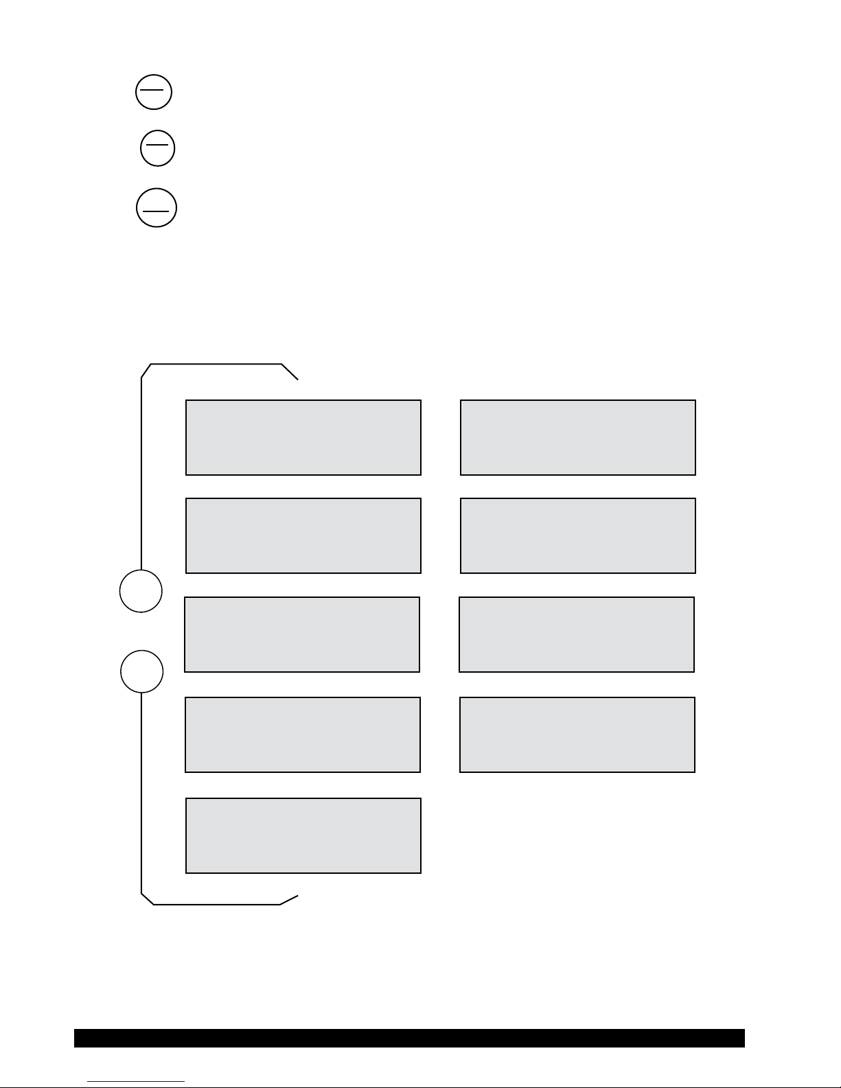
Pressing OPTIONS/TAB places you into the Options menu at the last option selected. The
following keys are active and perform as follows:
£
UP ARROW - Scrolls up through menu or selects new value from
list.
§
DOWN ARROW - Scrolls down through menu or selects new value
from list.
Brookeld Engineering Labs., Inc. Page 22 Manual No. M/03-165-D0410
Page 23
OPTION
TAB
F
OPTIONS/TAB - Toggles between options.
ENTER
AUTO
MOTOR
ON/OFF
ESCAPE
The Options menu screens will appear as shown in Figure III-1 if you cycle through the
possible options using the UP/DOWN arrows.
ENTER/AUTORANGE
RANGE
MOTOR ON/OFF/ESCAPE - Cancels current operation and backs user out
- Accepts the currently ashing option and
moves user to next level (if applicable) of the
selected option.
one menu level. Repeated pressing will back
the user out to the default screen. While in
the Options menu, the MOTOR ON/OFF/ESCAPE
key does not cause the viscometer motor to
turn on or off!
$
SETUP #
DTIME TO TORQUE $
OR
SETUP #
DTIME TO STOP $
2
DTIME TO TORQUE #
SET PRINT TIME $
OR
DTIME TO STOP #
SET PRINT TIME $
£
§
2
SET PRINT TIME #
DPC PROG OFF $
2
DPC PROG OFF #
DOWNLOAD A PROG $
2
DOWNLOAD A PROG #
RUN A PROG $
#
Figure III-1
OR
OR
OR
SET PRINT TIME #
DPC PROG ON $
DPC PROG ON #
DOWNLOAD A PROG $
Brookeld Engineering Labs., Inc. Page 23 Manual No. M/03-165-D0410
Page 24

On entry to the Options menu, the following rules regarding current viscometer operation are
in force:
1. Printer output will be suppressed when in the Custom Speed option, the Time to
Torque and Time to Stop options, the Download A Program and Run A Program
options. It will be continued when any other option is selected.
2. If the motor is ON when the user enters the Options menu, choices will be limited
to: CGS/SI units (under SETUP), °F/°C units (under SETUP), PRINTING
SELECTIONS and PC PROG.
3. The
last selected menu option will be ashing.
Selecting an Option
The following is a quick reference for entering and using the OPTIONS menu:
Press
OPTION
TAB
To enter Options Menu
F
Press
£
or
§
To scroll to a specic option
For Options:
Press
Press
OPTION
TAB
ENTER
AUTO
RANGE
To toggle between the choices available for a specic option when indicated
F
To select the ashing option
III.2 Setup
From the main Options screen, the user scrolls up or down until the following screen is
displayed:
SETUP è
DTIME TO TORQUE ê
Figure III-2
A press of the ENTER/AUTORANGE key takes you into the Setup sub-menu (Figure III-3). As in
the main Options menu, you can scroll up or down through the various Setup options. In order
to access all options, the motor must be turned off.
Brookeld Engineering Labs., Inc. Page 24 Manual No. M/03-165-D0410
Page 25

$
£
§
D°F(FAHRENHEIT) #
DCGS UNITS $
2
D°F(FAHRENHEIT) #
DCGSUNITS $
2
DCGS UNITS #
DSEQUENTIAL $
2
DSEQUENTIAL #
DPRINTSERIAL $
2
1
1
1
1
D°C(CENTIGRADE) #
DCGS UNITS $
D°F(FAHRENHEIT) #
DSIUNITS $
DCGS UNITS #
DINTERLEAVE $
DSEQUENTIAL #
DPRINTPARALLEL $
DCGS UNITS #
1
DCUSTOMSPEEDS$
DPRINT SERIAL #
DDATAAVERAGING $
OPTION
TAB
F
#
Figure III-3
III.2.1 Temperature Display
The DV-II+Pro viscometer can display temperature in either degrees Centigrade or degrees
Fahrenheit. On entry (assuming the viscometer is currently displaying °F) you will be
presented with:
D°F(FAHRENHEIT) è
DCGS UNITS ê
Brookeld Engineering Labs., Inc. Page 25 Manual No. M/03-165-D0410
Figure III-4
Page 26
A press of the OPTIONS/TAB key at this point will “toggle” between the two available
temperature scale options as shown in Figure III-5:
D°F(FAHRENHEIT) è
DCGS UNITS ê
To select the temperature display mode, press the ENTER/AUTORANGE key. You automatically
exit the Setup menu with the viscometer displaying temperature in the selected scale. You
must press the ENTER/AUTORANGE key to select the ashing option.
III.2.2 Units of Measurement
Selecting units of measurement is identical to that for temperature described above. The screen
display shows:
D°F(FAHRENHEIT) è
DCGSUNITS ê
A press of the OPTIONS/TAB key at this point allows the user to “toggle” between the two
available data display units as shown in Figure III-7:
"
Figure III-5
Figure III-6
D°C(CENTIGRADE) è
DCGS UNITS ê
D°F(FAHRENHEIT) è
DCGSUNITS ê
Pressing the ENTER/AUTORANGE key selects the display units, which are ashing, followed by an
exit of the Setup menu. You must press the ENTER/AUTORANGE key to select the ashing option.
III.2.3 Motor Speed Set Selection
This selection must be done with the motor off. Scrolling in the Setup options menu to the
speed set selection option yields the following screen display:
DCGS UNITS è
DSEQUENTIAL ê
"
É
Figure III-7
Figure III-8
DF(FAHRENHEIT) è
DSIUNITS ê
Brookeld Engineering Labs., Inc. Page 26 Manual No. M/03-165-D0410
Page 27

The last selected speed set option is displayed, in this case, Sequential. For each press of the
OPTIONS/TAB key, the display shows selectable options (Figure III-9). You must press the ENTER/
AUTORANGE key to select the ashing option.
DCGS UNITS è
DSEQUENTIAL ê
The speeds available in each of the above options are listed in Appendix G. The DV-II+Pro is
initially set up with the Sequential Speed Set at Brookeld prior to shipment.
III.2.3.1 LV/RV Speeds
In the case of Sequential or Interleave, a press of the ENTER/AUTORANGE key immediately selects
that option and exits the SETUP option menu.
III.2.3.2 Custom Speeds
Pressing the ENTER/AUTORANGE key when Custom Speeds is displayed results in the following
screen display:
DCGS UNITS è
1
DINTERLEAVE ê
É
Figure III-9
.01 h
°0.0 i
DCGS UNITS è
1
DCUSTOMSPEEDS ê
Figure III-10
Fifty-four (54) speeds are available for custom speed set selection (see Appendix G). You are
allowed to select up to nineteen (19) of these (54) available speeds. Speed 0.0 is automatically
included as one of the nineteen (19) speeds. Selecting a speed (or deleting a speed) is
accomplished by pressing the SET SPEED key while the desired speed is blinking. This will
cause an asterisk to appear (or to disappear if the speed is being cleared) to the left of the
speed. Trying to select more than nineteen (19) speeds will result in a “beep” for each press
of the SET SPEED key when over this limit. You may scroll up or down through the speed set in
selecting speeds. When done, a press of the ENTER/AUTORANGE key will take you back to the
default screen with the asterisked speeds now comprising the custom speed set. Regardless of
order chosen, speeds will appear in ascending order for run selection, beginning with speed 0.0
RPM.
Brookeld Engineering Labs., Inc. Page 27 Manual No. M/03-165-D0410
Page 28

III.2.4 Printer Output Port
Scrolling to the printer port option presents the following:
DSEQUENTIAL è
DPRINTSERIAL ê
"
É
Figure III-11
DSEQUENTIAL è
DPRINTPARALLEL ê
Pressing the OPTIONS/TAB key “toggles” between the two port choices. To select a printer output
port, press the ENTER/AUTORANGE key while the desired choice is blinking. This will cause the
DV-II+Pro to direct all further printer output to the chosen port while remaining in the Setup
menu. You must press the ENTER/AUTORANGE key to select the ashing option.
III.2.5 Data Averaging
This feature will perform a “rolling” average on the displayed % torque value and all other
displayed viscometer data derived from % torque. You are allowed to select the number of
readings over which averaging is being done, with ten (10) readings as the maximum. There
will be an initial delay as the rst average is performed and then no apparent delay as the
following readings are averaged (the viscometer takes approximately 4 readings per second).
The rolling average is described as follows given the selected reading number ‘X’:
1. The rst X readings are collected, placed in the averaging buffer, averaged and
displayed.
2. The rst reading in the averaging buffer is dropped; the next reading (the X + 1
reading) is placed in the buffer and the buffer is again averaged and displayed. Step
2 is repeated indenitely until the viscometer is shut off or the user selects a different
number of readings to average. The number of readings to be averaged will include
zero (0) as an average so that this option may effectively be turned off without turning
the viscometer off.
Notes:
1. The data averaging will only be applied to the data displayed by the viscometer.
No data averaging will be applied to the torque analog output signal.
2. When data averaging is other than zero (0) or one (1), a ashing A will be displayed
to the left of the % Torque sign as shown below.
CP 123.4 20.1C
10 RPM A% 19.7
Figure III-12
You must press the ENTER/AUTORANGE key to select the ashing option.
Brookeld Engineering Labs., Inc. Page 28 Manual No. M/03-165-D0410
Page 29

III.3 Time Modes
The Time Modes are provided to allow more exibility by unattended operating of the
viscometer during data gathering. The last selected option (i.e. Time to Torque or Time to
Stop) will be highlighted when scrolling to this option as shown in Figure III-13:
DSETUP è
DTIMETOTORQUE ê
Figure III-13
A press of the OPTIONS/TAB key will “toggle” between the two available timed modes as shown
in Figure III-14:
DSETUP è
DTIMETOTORQUE ê
"
É
DSETUP è
DTIMETOSTOP ê
Figure III-14
To enter the time for either of these options, press the ENTER/AUTORANGE key while the selected
option is blinking. Let’s start with Time To Stop.
Note: These two modes are immediately executed when input is complete. They do
not return to the default screen until running is complete. They can be stopped
at any time by a press of the MOTOR ON/OFF/ESCAPE key.
III.3.1 Time to Stop
On entry, the user is presented with the following screen display:
TIMED STOP
SET MIN’S: 00 èê
Note: If a time interval has already been set, the user may skip the time interval input
and go directly to the speed input screen by pressing the ENTER/AUTORANGE
key.
Using the UP and DOWN ARROW keys, the user enters a value for the minutes portion of
the time ramp. This value can be as high as 59 minutes. When satised, the user presses the
OPTIONS/TAB key again to enter the seconds setting display:
Brookeld Engineering Labs., Inc. Page 29 Manual No. M/03-165-D0410
Figure III-15
Page 30

TIMED STOP
SET SEC’S: 00 èê
Figure III-16
Using the UP and DOWN ARROW keys, the user enters a value for the seconds portion of the time
ramp. This value will be from zero (0 ) up to fty-nine (59) seconds. Press ENTER to accept the
value.
Note:
The value for either minutes or seconds must be other than zero or you cannot
advance to the RPM input screen (Figure III-17). Pressing the OPTIONS/TAB
or ENTER/AUTORANGE keys will cause the user to alternate between the
minutes input screen (Figure III-15) and the seconds input screen (Figure III-
16) until either minutes or seconds are anything but zero.
A press of the ENTER/AUTORANGE key allows the user to input the RPM selection. At this point,
the user will see a screen similar to Figure III-17; using the UP and DOWN ARROW keys, the
user sets the speed.
TIMED STOP
SELECT RPM:30 èê
Figure III-17
After selecting the speed, the user may review the values selected. If the user presses the
OPTIONS/TAB key, you will return to the minutes input screen of Figure III-15 where you
may change the minute input if so desired. Thereafter, continued pressing of the OPTIONS/TAB
key will toggle between the minutes and seconds input screens and the motor input screen. A
press of the MOTOR ON/OFF/ESCAPE key will cancel the timed stop operation and take the user
back to the screen of Figure III-14. Pressing the ENTER/AUTORANGE key will cause the DVII+Pro to accept the new values.
That done, the user is presented with the following screen:
At this point the user must press the ENTER/AUTORANGE key to begin the timed stop operation.
Any other key press will be ignored except the MOTOR ON/OFF/ESCAPE key which will cancel the
process and take the user back to the screen of Figure III-14 where you will have to begin all
over again.
We will assume that the user pressed the ENTER/AUTORANGE key. You will now be presented
with the following screen for the duration of the timed run:
Brookeld Engineering Labs., Inc. Page 30 Manual No. M/03-165-D0410
TIMED STOP
ENTER TO START
Figure III-18
Page 31

cP 123.5e6
MIN: 15 SEC: 13
Figure III-19
Note: When this mode has begun, a press of the MOTOR ON/OFF/ESCAPE key
will cancel the Timed Stop sequence and return the user to the screen of Figure
III-14. Also note that data will be displayed in the currently selected method
i.e. CGS or SI units. Pressing the SELECT DISPLAY key allows display of
alternate data values such as Shear Stress, Shear Rate or Torque.
The seconds display will decrement from fty-nine (59 ) to zero (0) in one (1) second intervals.
When seconds reaches zero (0), the minutes value will decrement by one (1) minute. This
will continue until all of the time has elapsed at which point the viscometer will display the
following screen:
cP 123e6
TIMED STOP DONE
Figure III-20
At this point the viscometer will stop the motor and continue to display this screen until any
key except the UP or DOWN ARROW key, the PRINT key or the SELECT DISPLAY key is pressed. The
user can, while this display is current, press the UP or DOWN ARROW keys to view the torque
and speed that were current at the time the display was frozen. The display would appear as
follows:
%=76.4 RPM=100
TIMED STOP DONE
Figure III-21
The display will switch between that of Figures III-20 and III-21 for each press of the UP
or DOWN arrow keys. A press of the PRINT screen would send one standard print line to the
attached printer for each press of the PRINT key. Pressing any key (except the UP or DOWN ARROW
keys, the PRINT key or the SELECT DISPLAY key) will cause the viscometer to exit the Time To
Stop mode and resume operation with the screen of Figure III-18 displayed awaiting another
Timed Stop run.
The user can press the PRINT key while in either of these two screens (Figures III-20 and III-21)
to send one standard print string to the attached printer as many times as the user presses the
PRINT key. In addition, the PRINT key can be pressed during the actual measurement to obtain
instantaneous data. Pressing any other key will exit this mode and return the viscometer to
normal operation.
Brookeld Engineering Labs., Inc. Page 31 Manual No. M/03-165-D0410
Page 32

III.3.2 Time to Torque
On entry to this mode, the user is presented with the following screen display:
TIMED TO TORQUE
SET TORQUE:00% èê
Figure III-22
Using the UP or DOWN ARROW keys, the user enters a value for the torque level that you wish to
reach.
Note: The value for torque must be other than zero (0) and less than or equal to ninety-
nine (99) percent or you will not be able to continue.
At this point, the user presses the OPTIONS/TAB key and the screen shown in Figure III-23
appears:
TIME TO TORQUE
SELECT RPM: 30 èê
Figure III-23
Using the UP or DOWN ARROW keys, the user selects a speed from the currently selected speed
set. If you had opted to use the LVRV sequential or interleaved speed sets, all those speeds
would be available by pressing the UP or DOWN ARROW keys. Conversely, if the user had
selected a custom speed set, you would be limited to those speeds comprising the custom
speed set. After selecting the speed, the user may press any one of three keys to continue:
the OPTIONS/TAB key, the MOTOR ON/OFF/ESCAPE key and the ENTER/AUTORANGE key. If the user
presses the OPTIONS/TAB key you will return to the torque input screen of Figure III-22 where
you may change the torque input if so desired. Therefore, continued pressing of the OPTIONS/
TAB
key will toggle between the torque input screens and the motor input screen. A press of
the MOTOR ON/OFF/ESCAPE key will cancel the time to torque operation and take the user back
to the screen of Figure III-13. Finally, pressing the ENTER/AUTORANGE key will cause the DVII+Pro to accept and store in EEPROM the new values (only) for the torque level and the
selected motor speed.
That done, the user is presented with the following screen:
TIME TO TORQUE
ENTER TO START
Figure III-24
At this point the user must press the ENTER/AUTORANGE key to begin the timed stop operation.
Any other key press will be ignored except the MOTOR ON/OFF/ESCAPE key which will cancel the
process and take the user back to the screen of Figure III-22 where you will have to begin all
over again.
Brookeld Engineering Labs., Inc. Page 32 Manual No. M/03-165-D0410
Page 33

We will assume that the user pressed the ENTER/AUTORANGE key. You will now be presented
with a screen similar to Figure III-25 for the duration of the timed torque run:
TORQUE = 24.2%
MIN: 15 SEC: 13
Figure III-25
Note: When this mode has begun, a press of the MOTOR ON/OFF/ESCAPE key will
cancel the time to torque sequence and return the user to the screen of Figure
III-13.
The seconds display will increment from zero (0) to fty-nine (59) in one (1) second intervals
and the current value of the viscometer torque will be updated continuously. When seconds
reaches fty-nine (59), the minutes value will increment by one (1) minute. This will continue
until the user selected torque value is attained at which point the viscometer will display the
following screen:
22MIN 54SEC: 85%
TIMED TORQ DONE
Figure III-26
At this point the viscometer will stop the motor and continue to display this screen until any
key (except the UP or DOWN ARROW keys, the PRINT key or SELECT DISPLAY key) is pressed. The
user can, while this display is current, press the UP or DOWN ARROW keys to view the viscosity
that was current at the time the display was frozen. The display would appear as follows:
cP 123.5e6
TIMED TORQ DONE
Figure III-27
The display will switch between that of Figures III-26 and III-27 for each press of the UP or
DOWN ARROW keys. As stated above, pressing any key (except the UP or DOWN ARROW or PRINT
keys) will cause the viscometer to exit the Time To Torque mode and resume operation with the
screen of Figure III-22 displayed awaiting another Timed Torque run.
The user can press the PRINT key while in either of these two screens (Figures III-26 and III-27)
to send one standard print string to the attached printer as many times as the user presses the
PRINT key. In addition, the PRINT key can be pressed during the actual measurement to obtain
instantaneous data. Pressing any other key will exit this mode and return the viscometer to
normal operation.
Note: For both of the methods of Sections III.3.1 and III.3.2 the following apply:
1. For the Timed Stop method, the DV-II+Pro viscometers will retain the last value for
the time interval so that it will become the default the next time the user elects to use
this method.
Brookeld Engineering Labs., Inc. Page 33 Manual No. M/03-165-D0410
Page 34

2. For the Time To Torque method, the DV-II+Pro viscometers will retain the last
entered torque value for use when next the user elects to perform a time to torque test.
3. The user can set up a desired print interval time, then set the viscometer to the
continuous print mode and nally initiate either of the timed modes of operation.
While setting up the timed mode parameters, continuous print operation will cease.
However, upon starting the timed operation, the DV-II+Pro will output an initial data
string to the printer and then continue printing data strings (at the user dened time
interval) for the duration of the timed run. At the end of the timed run, continuous
printing will again be disabled and the user may print single strings (of the nal data
point) at your option until you exit the timed mode. Upon returning to the default
operation mode, continuous printing will again resume at the user selected time
interval. In a similar manner, if you are in the once-per-PRINT -key-press mode, when
you enter the timed mode of operation you will be able to print data strings at any
time during the timed mode by pressing the PRINT key.
III.3.3 Print Time Interval
This option is used to set the print time interval to the selected printer. Scroll to Set Print Time,
as shown in Figure III-28:
D TIMED TO TORQUE è
SETPRINTTIME ê
Figure III-28
Press the ENTER/AUTORANGE key. On entry, Figure III-29 is displayed:
PRINT INTERVAL
SET MIN’S: 00 èê
Figure III-29
Using the UP and DOWN ARROW keys, enter a value for the minutes between successive print
strings. This value can be as high as fty-nine (59) minutes and as low as 00.
When satised, press the OPTIONS/TAB key to enter the seconds setting display:
PRINT INTERVAL
SET SEC’S: 00 èê
Using the UP and DOWN ARROW keys, enter a value for the seconds portion of the print interval.
This value can be between zero (0) and fty-nine (59 )seconds.
Brookeld Engineering Labs., Inc. Page 34 Manual No. M/03-165-D0410
Figure III-30
Page 35

Note: The value for minutes or seconds must be other than zero (0) or you will print
continuously when you exit this mode. A press of the MOTOR ON/OFF/
ESCAPE key would exit this option and take you back to the screen of Figure
III-28.
Continued pressing of the OPTIONS/TAB key will toggle between the minutes and seconds input
screens. Press the ENTER/AUTORANGE key to accept the new values for print interval in minutes
and seconds. You will now be in the screen display of Figure III-28 where you may re-enter
the print interval mode, or exit to the default screen (Figure II-5) by pressing the MOTOR ON/
OFF/ESCAPE key.
Activating print selections in the Print mode can only be done by exiting to the main menu
and pressing the PRINT key for four (4) seconds. “P%” will ash in front of the torque reading,
conrming that you are now in the Print Interval mode. Pressing PRINT for one (1) second
thereafter will disable the Print mode and remove the “P%” from the display.
III.3.4 PC Program (On/O)
This option causes the serial port of the DV-II+Pro viscometer to go into a high speed output
mode (approximately 3 print lines per second) for use with Brookeld WINGATHER®
software program. When ON, you may enter the Options menu but will not be allowed to
make any option selections until the PC PROG is turned OFF. All front panel keys will
function normally when you turn the option ON and return to normal viscometer operation by
pressing the MOTOR ON/OFF/ESCAPE key. When OFF, the DV-II+Pro will return to the last set
print time interval when printing is resumed.
Note:
WINGATHER® software can be used for data acquisition and analysis.
Rheocalc32 software can be used for complete external control of DV-
II+Pro.
From the Options menu, scroll to the screen shown in Figure III-31:
SET PRINT TIME è
D PCPROGOFF ê
Figure III-31
Press the OPTIONS/TAB key to display Figure III-32:
SET PRINT TIME è
D PCPROGON
Figure III-32
ê
Pressing the OPTIONS/TAB key would return you to the screen display of Figure III-31. Repeated
pressing of the OPTIONS/TAB key would cause you to toggle back-and-forth between the displays
of Figure III-31 and Figure III-32.
To turn high speed output ON, press the ENTER/AUTORANGE key when the appropriate screen is
displayed. Then press the MOTOR ON/OFF/ESCAPE key to exit the Setup mode. This returns you
Brookeld Engineering Labs., Inc. Page 35 Manual No. M/03-165-D0410
Page 36

to the default screen display and resumes normal viscometer operation with high speed output
enabled and normal printer operation using the last entered print time interval.
Note: For access to B.E.V.I.S. option, PC PROG must be OFF.
III.3.5 Download a Program
Please refer to Section IV for details on how to create a program before proceeding with this
section.
In the Options menu, scroll to the screen shown in Figure III-33:
D PC PROG OFF è
DOWNLOADAPROG ê
Figure III-33
Refer to Section IV for information on how to create B.E.V.I.S. programs on a PC which can
be downloaded to the DV-II+Pro Programmable Viscometer.
Press the ENTER/AUTORANGE key to download a B.E.V.I.S. program as shown in Figure III-34:
LOAD TO SLOT#1èê
PRESSENTERKEY
Figure III-34
Select a number from one (1) to four (4) using the UP/DOWN ARROW keys assign a storage
location for the program to be downloaded.
Note: Remember to keep track of what program is in what slot. If you elect to
download a new program to an active slot, you will overwrite the program
currently residing in that slot. The programs are saved automatically when the
viscometer is turned off.
After selecting the slot number, press the ENTER/AUTORANGE key and the screen shown in Figure
III-34 changes as follows: the top line ashes while the bottom line disappears. This ashing
screen will be displayed for as long as it takes to download the program. At the end of the
download, Figure III-35 is displayed:
DOWNLOAD DONE TO
EXIT PRESS A KEY
If a PC is not attached, Figure III-36 will be displayed:
Brookeld Engineering Labs., Inc. Page 36 Manual No. M/03-165-D0410
Figure III-35
Page 37

B.E.V.I.S. ERROR
NO PC ATTACHED
Figure III-36
A press of any key (except the MOTOR ON/OFF/ESCAPE key) will take the user back a level to
Figure III-34 where you may elect to download another program or, with a press of the MOTOR
ON/OFF/ESCAPE key, return to the screen of Figure III-33.
III.3.6 Run a Program
In the Options menu, scroll to the screen shown in Figure III-37:
DOWNLOAD A PROG è
RUNAPROG ê
Figure III-37
Press the ENTER/AUTORANGE key to run a B.E.V.I.S. program as shown in Figure III-38:
RUN PGM SLOT#1èê
PRESSENTER
Figure III-38
Using the UP/DOWN ARROW keys, select one of the four (4) stored programs. Press the ENTER/
AUTORANGE key. Any attempt to select a program slot that does not contain a program will
result in a double beep for each key press. When a valid program slot is selected, the screen in
Figure III-39 is displayed:
PRINT KEY = LIST
ENTER KEY = RUN
Figure III-39
At this point, you may elect to print the B.E.V.I.S. program by pressing the PRINT key or start
the program immediately by pressing the ENTER/AUTORANGE key (remember: pressing the
MOTOR ON/OFF/ESCAPE key will stop the current operation and bring you back one menu level).
You may elect to print the program, to conrm the slot choice as correct or simply to have it
available later when reviewing data. If you elect to print the program, you will return to the
screen of Figure III-38 after the program is nished printing. Pressing the ENTER/AUTORANGE
key exits the screen of Figure III-38 and the program will start running.
On program start, the screen could be any of the screens possible when running a B.E.V.I.S.
program. A typical screen might be:
Brookeld Engineering Labs., Inc. Page 37 Manual No. M/03-165-D0410
Page 38

USE SPINDLE 31
PRESS A KEY
Figure III-40
where the operator is instructed to mount a spindle 31 and then press a key to continue. Or you
might see:
SET TEMP TO 100C
PRESS A KEY
Figure III-41
followed by:
WAIT TEMP 100C
P1 S00/12 00:14
Figure III-42
Here, the B.E.V.I.S. program is waiting for the temperature to reach one hundred (100) °C
before it continues to the next program step. Also displayed is the program number (P1), the
step number and the total program steps (S00/12) and the elapsed time since the program (or
step) began (00:14). While in this “wait state” you can press the OPTIONS/TAB key to see the
viscometer default screen in Figure III-43; the PGM will be ashing.
CP 123.4 55.1C
10 RPM PGM% 63.7
Figure III-43
The DVLOADER Software is used to create, save, print, and down load programs to the DVII+Pro Viscometer. The next section explains how to use the DVLOADER software.
Brookeld Engineering Labs., Inc. Page 38 Manual No. M/03-165-D0410
Page 39

IV. DVLOADER SOFTWARE
The DVLOADER software is a WINDOWS-based program provided on a CD which comes with the
Programmable DV-II+Pro Viscometer.
IV.1 B.E.V.I.S. Overview
DVLOADER utilizes B.E.V.I.S. (Brookeld Engineering Viscometer Instruction Set), a
scripting language that allows for the creation of programs to control the Programmable DVII+Pro Viscometer. Programs are created on a PC, then loaded into the viscometer using the
DVLoader software. Some testing capabilities that are possible include the following:
• Repeatedly run the same test program for quality control purposes.
• Wait for a specic condition before continuing with the test (i.e. a torque value, a temperature value, a key press, etc.).
• Run the viscometer at any of the speeds in the Custom Speed menu.
• Display messages to the screen or an attached printer to aid the operator.
• An internal clock that keeps time between each printed data line (this time is displayed as
the last parameter on each printed line). This provides a consistent time base for the collected data.
Brookeld Engineering Labs., Inc. Page 39 Manual No. M/03-165-D0410
Page 40

IV.2 Description of B.E.V.I.S. Commands
Command Code Required Parameter Command Description
WTI Time The program waits at this step until the specied time
(MM:SS) elapses.
WPT % Torque value The program waits at this step until the current % torque
(%) equals the specied value.
WTP Temperature value The program waits at this step until the current temperature
(°C) equals the specied value.
WKY 16 character (or less) The specied message is displayed on the top line of the DV text message II+ display while PRESS A KEY is displayed on the bottom
line of the DV-II+Pro. The program waits at this step until a
viscometer key is pressed. While waiting at this step, the
viscometer produces a beep every few seconds to remind the
operator that a keypress is required to continue.
If a print interval was enabled (see SPI) at the time this
command is executed, the data print timer continues to count
up. If the print interval elapses and a key has not yet been
pressed, a line of data displaying the time since the last data
print is printed as soon as a key is pressed.
SSN Speed value The DV-II+Pro begins rotating at the specied speed. This
(RPM) can be any of the speeds listed in the Speed list of the
DVLoader software. These speeds are the same as those
listed in the Custom Speeds list in the viscometer’s Options
menu.
SPI Time The DV-II+Pro begins printing data to the selected printer
(MM:SS) (serial or parallel; as selected in the DV-II+Pro menus) at the
rate specied. MM:SS is minutes:seconds.
SSP Two digit spindle code Calculations of viscosity, shear stress, and shear rate are
performed based on the specied spindle code. This
command overrides the spindle currently entered via the
keypad on the DV-II+Pro.
STZ N/A Sets the data print timer clock back to zero.
PDN N/A The DV-II+Pro immediately prints a data string to the se-
lected printer (serial or parallel; as selected in the DV-II+Pro
menus).
PLN 16 character (or less) The DV-II+Pro prints the specied message to the selected
text message printer (serial or parallel; as selected in the DV-II+Pro
menus).
By using various combinations of the above commands, programs are created that automatically
control the viscometer and collect data (via an attached printer) from the Programmable DV-II+Pro
Viscometer.
Brookeld Engineering Labs., Inc. Page 40 Manual No. M/03-165-D0410
Page 41

IV.3 Creating a B.E.V.I.S. Program
Start the DVLOADER software by clicking on its associated icon. For Windows 95/98/
NT/2000, click the Start button; select Run; enter the name of the program to execute
{dvloader.exe}; then click OK.
The B.E.V.I.S. commands are displayed in a list box on the main screen. This list box displays
the commands available for creating programs. Clicking on the Insert button inserts the
highlighted command (WTI, as shown in Figure IV-1) into the selected line in the program
grid. Double-clicking on a line in this list box also inserts the command into the grid shown in
Figure IV-2.
The icons to the left of the command descriptions indicate
the type of command:
A command to wait for a condition.
Figure IV-1
A command to set a program parameter.
A command to send information to an attached
printer.
Brookeld Engineering Labs., Inc. Page 41 Manual No. M/03-165-D0410
Page 42

1 SSN 50.0
2 WTI 00:30
3 SPI 00:05
4 WPT 75 .0
5 SSN 25.0
6 WTI 00:10
7 WPT 75 .0
8 SSN 0.0
9
10
11
12
13
14
15
16
17
18
19
20
21
22
23
24
25
Figure IV-2 shows the grid where the operator programs are created.
It is used to view and edit the B.E.V.I.S. programs. When the
software starts, an empty grid appears on the left of the screen. You
can choose up to 25 commands for your program. Highlight each
command in the list box to the right of this grid, then click on the
Insert button to insert that same command into the highlighted line
of the grid. This same insertion task can also be accomplished by
double-clicking on the appropriate command in the list box to the
right.
In the case of a speed command (SSN), the Speeds list box becomes
enabled when the cursor is placed in the parameter column for
an SSN command. Click on the down arrow to display a list of
available speeds. Click on the desired speed, and it will be inserted
into the appropriate parameter column in the program grid. The same
applies to the spindle command (SSP).
Figure IV-2
The buttons shown on the main screen are explained below.
Select the COM (RS-232) port the Programmable DV-II+Pro Viscometer is connected
to from the COM Port drop down list.
Click the Open File button to load existing B.E.V.I.S. programs.
Click the Save File button to save the B.E.V.I.S. program displayed in the grid.
Click the Print button to print the B.E.V.I.S. program displayed in the grid.
Click the Insert button to insert the B.E.V.I.S. command selected in the Commands box
into the selected row in the program grid.
Brookeld Engineering Labs., Inc. Page 42 Manual No. M/03-165-D0410
Page 43

Click the Delete button to delete the B.E.V.I.S. command in the selected row of the program grid.
Click the Up button to move the B.E.V.I.S. command in the selected row of the program
grid up one row.
Click the Down button to move the B.E.V.I.S. command in the selected row of the program grid down one row.
Click the Clear button to clear the grid of all B.E.V.I.S. commands. Once cleared, the
commands cannot be retrieved.
Downloads a B.E.V.I.S. program from the PC to the DV-II+Pro
Exits the DVLOADER software program and returns the user to the WINDOWS Program Manager.
IV.4 Downloading a B.E.V.I.S. Program
Before down loading a B.E.V.I.S. program to the viscometer, ensure the following have been
checked:
• The appropriate cable (BEL Part# DVP-80) is connected between the selected COM port of
the PC and the viscometer.
• The DV-II+Pro motor must be OFF.
• Set PC PROG to “OFF.”
• The Programmable DV-II+Pro is at the down load screen: OPTIONS|DOWNLOAD A
PROG|LOAD TO SLOT#x where x is slot 1,2,3, or 4. See Section III.6.
With the LOAD TO SLOT#x screen displayed, choose a storage slot using the DV-II+Pro
arrow keys then press the ENTER/AUTO RANGE key on the viscometer. If after 5
seconds, the viscometer cannot communicate with the DVLoader program, the B.E.V.I.S.
ERROR NO PC ATTACHED
message is displayed and a beeping sound is heard. If a
connection is established, the Down Load button on the PC software becomes enabled , and
the DV-II+Pro screen displays DOWNLOAD PROG TO STORAGE SLOT #1. Click on
this button to down load the displayed program to the DV-II+Pro. When the down load is
complete, the DV-II+Pro displays DOWNLOAD DONE TO EXIT PRESS A KEY.
At this point the program in the DV-II+Pro can be printed and/or run from the viscometer.
Brookeld Engineering Labs., Inc. Page 43 Manual No. M/03-165-D0410
Page 44

Click on this button to exit the DVLOADER software.
Note: This is an important nal step because it allows the RS232 port to be used for
output from the DV-II+Pro to a serial printer or PC.
IV. 5 Example Programs
The following example programs can also be found on the DVLoader disk that was included with
the DV-II+Pro Programmable Viscometer:
Program 1: Pre-Shear
Command Command Description Parameter Comments
PLN Print text now Preshearing now print user message
SSN Set viscometer speed 50.0 run at 50 RPM
WPT Wait for % torque 90.0 wait until 90% torque is reached
PLN Print text now Collecting data print user message
SPI Set print interval 00:10 begin printing data at 10 second
intervals
SSN Set viscometer speed 10.0 run at 10 RPM
WTI Wait for time interval 01:40 wait at this step for 1 minute and
40 seconds, effectively printing 10
data lines
Program 2: For use with an external temperature controller
Command Command Description Parameter Comments
WTP Wait for temperature 40.0 wait until temperature = 40°C
(as an example, a Thermosel/Controller can be used for temperature
control)
WTI Wait for time interval 05:00 soak time; allow temperature to
settle
SSN Set viscometer speed 25.0 run at 25 RPM
SPI Set print interval 00:30 begin printing data at 30 second
intervals
WTI Wait for time interval 06:00 wait at this step for 6 minutes,
effectively printing 12 data lines
Brookeld Engineering Labs., Inc. Page 44 Manual No. M/03-165-D0410
Page 45

Program 3: Wait for cure (time to torque measurement)
Command Command Description Parameter Comments
SSP Set spindle 31 set to a number 31 spindle
SSN Set viscometer speed 100.0 run at 100 RPM
SPI Set print interval 00:05 begin printing data at 5 second
intervals
WPT
Wait for % torque 85.0
wait until % torque = 85; a curing
cycle
Program 4: Spring relax
Command Command Description Parameter Comments
WKY Wait for a key press Wind to 100% tell operator to wind spindle
until 100% torque is reached
WPT
Wait for % torque 100.0
wait until 100% torque is reached
WKY Wait for a keypress Release spindle tell operator to release the spindle
SPI Set print interval 00:01 begin printing data at 1 second
intervals
WPT
Wait for % torque
0.0 wait for spindle to completely
unwind to 0% torque
Program 5: Variable speed
Command Command Description Parameter Comments
SSN Set viscometer speed 5.0 run at 50 RPM
WTI Wait for time interval 00:10 wait for 10 seconds
PDN Print data point now print one data point
SSN Set viscometer speed 10 run at 10 RPM
WTI Wait for time interval 00:10 wait for 10 seconds
PDN Print data point now print one data point
SSN Set viscometer speed 20 run at 20 RPM
WTI Wait for time interval 00:10 wait for 10 seconds
PDN Print data point now print one data point
SSN Set viscometer speed 5.0 run at 50 RPM
WTI Wait for time interval 00:10 wait for 10 seconds
PDN Print data point now print one data point
Brookeld Engineering Labs., Inc. Page 45 Manual No. M/03-165-D0410
Page 46

V. AUTOMATED DATA GATHERING & ANALYSIS
There are two choices of applications software that can be purchased from Brookeld or an
authorized dealer for this purpose:
1. WINGATHER32 is a data gathering program which collects data output from the
DV-II+Pro and provides the capability to perform graphical analysis and data le
management.
2. RHEOCALC32 is a control program which operates the DV-II+Pro in external control
via a PC as well as a data gathering program for the purpose stated above in the
WINGATHER32 description.
V.1 WINGATHER32
Important features and benets in WINGATHER32 which enhance operator versatility in
performing viscosity tests include the following:
• 32-bit operation for rapid performance
• Compatible with Windows 95, 98, ME, 2000 and NT operating systems for exible
operation.
• Brookeld’s DV Loader software (for setting up test programs) is integrated into
WINGATHER32. DV Loader is an easy-to-use, structured command language which makes
detailed viscosity tests simple to program (see Section IV).
• Easy-to-use data gather modes including automatic follow up events (save data, analyze data,
print data)
• Manual scaling of plot axes
• Auto range feature which shows in screen display the complete viscosity range which can be
measured at any shear rate for a specic spindle geometry
• Concurrent plotting of six data sets on one graph
The following gures show the principal screens associated with WINGATHER32:
Brookeld Engineering Labs., Inc. Page 46 Manual No. M/03-165-D0410
Figure V-1: Dashboard Screen
Page 47
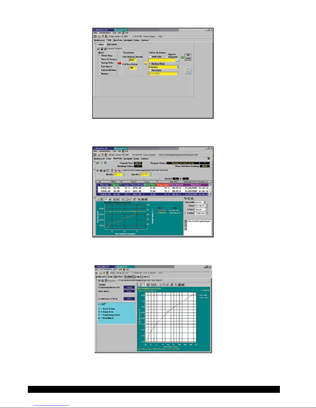
Figure V-2: Test Selection Screen
Figure V-3: Run/Data Screen
Brookeld Engineering Labs., Inc. Page 47 Manual No. M/03-165-D0410
Figure V-4: Analysis Screen
Page 48

V.2 RHEOCALC32
Important features and benets in Rheocalc32 which enhance operator versatility in performing
viscosity tests include the following:
• Compatible with Windows 95, 98, ME, 2000 and NT operating systems for exible operation
• 32-bit operation for rapid performance
• Easy-to-use, structured command language to make viscosity tests easier to program
• Display of current temperature set point
• Concurrent plotting of four data sets on one graph
• Various mathematical models for data analysis
• Auto range feature which shows in screen display the complete viscosity range which can be
measured at any shear rate for a specic spindle geometry
The following gures show the principal screens associated with Rheocalc32
Brookeld Engineering Labs., Inc. Page 48 Manual No. M/03-165-D0410
Figure V-5: Dashboard Screen
Figure V-6: Test Program Setup Screen
Page 49

Figure V-7: Run Data Screen
Figure V-8: Analysis Screen
Brookeld Engineering Labs., Inc. Page 49 Manual No. M/03-165-D0410
Page 50

Appendix A - Cone/Plate Viscometer Set-Up
Pilot Light
(red)
Toggle Swtich
Contact Light
(yellow)
Sliding Reference
Marker
Micrometer
Adjustment Ring
This Cone/Plate version of the DV-II+Pro uses the same operating instruction procedures as described in this manual. However, the “gap” between the cone and the plate must be veried/adjusted
before measurements are made. This is done by moving the plate (built into the sample cup) up
towards the cone until the pin in the center of the cone touches the surface of the plate, and then by
separating (lowering) the plate 0.0005 inch (0.013mm).
When operating the Cone/Plate at elevated temperature, the gap must be set with the cup and spindle
equilibrated at that temperature. Maximum temperature for Cone/Plate operation is 100ºC.
Programmable DV-II+Pro Cone/Plate Viscometers, S/N 50969 and higher, have an Electronic Gap
Setting feature. This feature enables the user to easily nd the 0.0005 inch gap setting that was established at Brookeld prior to shipment.
The following information explains how to set the Electronic Gap and verify calibration of the DVII+Pro Viscometer.
A.1 ELECTRONIC GAP SETTING FEATURES
TOGGLE SWITCH allows you to enable/disable the
Electronic Gap Setting Feature: left position is
OFF (disabled), right position is ON (enabled).
PILOT LIGHT is the red (LED) light; when illumi-
nated, it means the Electronic Setting Function is
sensing (enabled).
CONTACT LIGHT is the yellow (LED) light; when it
rst turns on, the “hit point” has been found.
SLIDING REFERENCE MARKER is used after nding the
“hit point;” it is the reference for establishing the
0.0005 inch gap.
MICROMETER ADJUSTMENT RING is used to move the cup up or down in relation to the cone spindle.
Figure A1
Turning the ring left (clockwise) lowers the cup; turning it right (counterclockwise) raises the cup.
Each line on the ring represents one scale division and is equivalent to 0.0005 inch movement of
the plate relative to the cone.
Brookeld Engineering Labs., Inc. Page 50 Manual No. M/03-165-D0410
Page 51

A.2 SETUP
Bath/Circulator
Bath
Inlet
Bath
Outlet
Sample
Cup
(CPE-44Y
or
CPE-44P)
Cup
Outlet
Cup
Inlet
Spindle
Wrench
(CPE) Cone
These surfaces
must be clean!
Coupling Nut
Micrometer
Adjustment
Ring
Do Not hit the
CONE with the CUP!
1. Be sure that the Viscometer is securely
mounted to the Laboratory Stand, leveled
and zeroed with no cone or cup attached and
0% torque is displayed.
2. Figure A2 shows a typical water bath setup.
Connect the sample cup inlet/outlet ports to
the water bath inlet and outlet and set the
bath to the desired test temperature. Allow
sufcient time for the bath to reach the test
temperature.
3. The Viscometer has been supplied with a
special cone spindle(s) which contains the
Electronic Gap Setting feature. The “CPE”
part number designation on the cone veries
the Electronic Gap Setting feature.
Figure A2
Note: The “CPE” cone or cup cannot be
used with earlier DV-II+ cone/plate Viscometers (below S/N50969) which do not have
the electronic gap setting feature.
4. With the motor off, thread the cone spindle
by using the spindle wrench to secure the
viscometer coupling nut (see Figure A3);
gently push up on the coupling nut and hold
this securely with the wrench. Thread the
cone spindle by hand.
Note: Left Hand Threads.
5. Attach the cup, taking care not to hit the
cone with the cup (Figure A4).
Figure A3
Brookeld Engineering Labs., Inc. Page 51 Manual No. M/03-165-D0410
Figure A4
Page 52

A.3 SETTING THE GAP
Moves Away
from Hit Point
(clockwis e)
LEFTx
Moves Towards
Hit Point
(counter-clockwise)
RIGHT
Full Scale
Division Marks
Sliding
Reference
Marker
1. Move the toggle switch to the right; this will
turn on (enable) the Gap Setting Feature.
The Pilot (red) light will be illuminated.
2. If the contact light (yellow) is illuminated,
turn the micrometer adjustment ring clockwise (as you look down on the instrument)
until the light is no longer illuminated (see
Figure A5
).
3. If the yellow contact light is not illuminated,
slowly turn the micrometer adjustment ring
in small increments (one or two scale divisions) counter-clockwise.
Continue moving the micrometer adjust
ment ring slowly counter-clockwise until the
contact light (yellow) rst turns on. THIS
IS THE “HIT POINT
.”
4. Adjust the sliding reference marker, right or
left, to the closest full scale division mark
(see Figure A6)
.
5. Turn the micrometer adjustment ring one
scale division to the left to meet the line on
the sliding reference marker. THE YEL-
LOW CONTACT LIGHT SHOULD GO
OFF.
6. You have established the gap space needed
for measurement. Now turn the toggle
switch OFF (left); the red pilot light should
go off.
The viscosity of electrically conductive uids
may be affected if readings are taken with the
Electronic Gap Setting feature “on”. Be sure to
shut the feature “off” before taking readings!
Figure A5
Figure A6
7. Carefully remove the sample cup.
Notes:
1. The cup may be removed and replaced without
resetting the gap if the micrometer adjustment ring
has not been moved.
2. Remove the spindle from the viscometer when
3. Re-establish the hit point every time the spindle is
Brookeld Engineering Labs., Inc. Page 52 Manual No. M/03-165-D0410
cleaning.
attached/detached.
Page 53

A.4 VERIFYING CALIBRATION
1. Determine the appropriate sample volume. Refer to Table A1 to determine the correct sample
volume required for the spindle to be utilized.
2. Select a Brookeld Viscosity Standard uid that will give viscosity readings between 10% and
100% of full scale range. Refer to Appendix B for viscosity ranges of cone spindles; ranges
listed apply to CPE cones.
Do not use a silicone viscosity standard uid with a viscosity value greater than 5000 cP with
a Cone/Plate. Brookeld offers a complete range of mineral oil viscosity standards suitable
for use with Cone/Plates for viscosities above 5,000 cP or shear rates above 500 sec
-1
; see
Table E2 in Appendix E for a list of available uids.
It is best to use a viscosity standard uid that will be close to the maximum viscosity for a
given cone spindle/speed combination.
Example: LVDV-II+ Viscometer, Cone Spindle CPE-42, Brookeld Silicone Viscosity
Standard having a viscosity of 9.7 cP at 25°C
At 60 RPM, the full scale viscosity range is 10.0 cP. Thus, the Viscometer reading should be
97% torque and 9.7 cP viscosity ± 0.197 cP. The allowable error (±0.197 cP) is a combination
of Viscometer accuracy and uid tolerance (refer to Interpretation of Calibration Test
Results
in
Appendix E).
3. With the motor off, remove the sample cup and place the viscosity standard uid into the cup.
Table A1
Cone Part No.
CPE-40
CPE-41
CPE-42
CPE-51
CPE-52
Sample Volume
0.5 ml
2.0 ml
1.0 ml
0.5 ml
0.5 ml
4. Attach the sample cup to the Viscometer and allow sufcient time for the sample, cup and
cone to reach temperature equilibrium.
5. Turn the motor on. Set the desired speed(s). Measure the viscosity and record the reading in
both % torque and centipoise (cP).
Note: The cone spindle must rotate at least ve (5) times before a viscosity reading
is taken
6. Verify that the viscosity reading is within the allowable 1% deviation, as explained earlier, for
the specic viscosity standard uid(s) that you are using.
* The CPE designation on the cone spindle indicates use with Electronic Gap Setting Cone/
Plate Viscometers/Rheometers only.
Brookeld Engineering Labs., Inc. Page 53 Manual No. M/03-165-D0410
Page 54

A.5 VISCOSITIES OF DISTILLED WATER AND A 5 CPS STANDARD @ 25°C TESTED WITH
CONE SPINDLES #40 AND #41.
Distilled water and a 5 CPS Brookeld Viscosity Standard Fluid rated 4.7 cP and at 25°C
were tested using a Brookeld LVDV-II+Pro C/P Viscometer with Cone Spindles CPE-40 and
CPE-41. Temperature was maintained at 25°C by using a Brookeld TC-502P Programmable
Temperature Bath. Samples were equilibrated at 25°C for 15 minutes prior to testing.
Conditions were used such that results were between 10 and 100% of Full-Scale Range or
“FSR”.
The attached graph shows that the viscosity of each material, when measured with the CPE40 Cone Spindle, is essentially constant over the range of speeds tested. However, viscosity
increases with increasing speed for each material when using Cone Spindle CPE-41. This
agrees with viscosity behavior discussed in the technical literature on the same subject. That
is, the chance of secondary ows and therefore, erroneous readings, increases as:
1. the sample viscosity decreases,
2. the cone angle increases, and
3. the cone angular velocity (or testing speed) increases.
Figure A7 summarizes the results for viscosity vs. speed. Note that the 0.90 cP reading, for
distilled water was made at 40 rpm (11.5% Torque) corresponding to 300 s-1. Liquids with
higher viscosities may be measured with on-scale torques at lower speeds (and shear rates).
Therefore, if it is desired to test very-low-viscosity materials at very-low-shear rates, the tester
should seriously consider using an air-bearing instrument with a low-angle cone.
Figure A-7: Distilled water and 5 CPS standard results at 25°C.
Brookeld Engineering Labs., Inc. Page 54 Manual No. M/03-165-D0410
Page 55

Appendix B - Viscosity Ranges
Viscosity Range Tables
Viscosity ranges shown are for operational speeds 0.1 through 200 rpm.
LV Viscometer with LV spindles #1-4 and
RV/HA/HB Viscometers with spindles #1-7
Viscosity Range (cP)
Viscometer
LVDV-II+
RVDV-II+
HADV-II+ 200 80,000,000
HBDV-II+ 800
Minimum
15 6,000,000
100 40,000,000
Maximum
320,000,000
Small Sample Adapter and Thermosel
SSA and
Thermosel
LVDV-II+ RVDV-II+
Spindle
S
SC4-14
S
SC4-15
S
SC4-16
58.6 - 1,171.00
23.4 - 468,650
60 - 1,199,700 640 - 12,800,000 1,280 - 25,600,000 5,120 - 102,400,000 .29N
625 - 12,500,000 1,250 - 25,000,000
250 - 5,000,000 500 - 10,000,000 2,000 - 40,000,000
SC4-18 1.5 - 30,000 16 - 320,000 32 - 640,000 128 - 2,560,000 1.32N
SC4-21 2.4 - 46,865 25 - 500,000 50 - 1,000,000 200 - 4,000,000 .93N
Viscosity (cP)
HADV-II+ HBDV-II+
Shear
Rate
sec-1Å
5,000 - 100,000,000 .40N
.48N
SC4-25 240 - 4,790,000 2,560 - 51,200,000 5,120 - 102,400,000 20,480 - 409,600,000 .22N
SC4-27 11.7 - 234,325 125 - 2,500,000 250 - 5,000,000 1,000 - 20,000.000 .34N
SC4-28 23.4 - 468,650 250 - 5,000,000 500 - 10,000,000 2,000 - 40,000,000 .28N
SC4-29 46.9 - 937,300 500 - 10,000,000 1,000 - 20,000,000 4,000 - 80,000,000 .25N
SC4-31 15 - 300,000 160 - 3,200,000 320 - 6,400,000 1,280 - 25,600,000 .34N
SC4-34 30 - 600,000 320 - 6,400,000 640 - 12,800,000 2,560 - 51,200,000 .28N
S
This spindle used with Small Sample Adapter only
Å N represents speed in RPM. For example, spindle SC4-14 operated at 5 rpm has a shear rate of
0.40 x 5 = 2.0 sec
-1
Range and spindle constant information for spindles 82 and 83 are listed on Brookeld Technical Sheet T95-954. Consult Brookeld or your Brookeld dealer for information on spindles
81 and 37.
Brookeld Engineering Labs., Inc. Page 55 Manual No. M/03-165-D0410
Page 56

UL Adapter
UL Spindle
YULA-15 or 15Z 1 - 2,000 3.2 - 2,000 6.4 - 2,000 25.6 - 2,000
LVDV-II+
RVDV-II+ HADV-II+
Viscosity (cP)
HBDV-II+
DIN Adapter Accessory
DAA
Spindle
85 0.6 - 5,000 6.1 - 5,000 12.2 - 5,000 48.8 - 5,000
86 1.8 - 10,000 18.2 - 10,000 36.5 - 10,000 146 - 10,000
87 5.7 - 50,000 61 - 50,000 121 - 50,000 485 - 50,000
LVDV-II+ RVDV-II+
Viscosity (cP)
HADV-II+
HBDV-II+
Spiral Adapter
Spiral
Spindle
SA-70 98 - 98,500 1,050 - 1,050,000 2,100 - 2,100,000 8,400 - 8,400,000
LVDV-II+ RVDV-II+ HADV-II+
Viscosity (cP)
HBDV-II+
Shear Rate
sec-1
1.22N
Shear Rate
sec-1
1.29N
1.29N
1.29N
Shear Rate
sec-1
0.667N
Cone/Plate Viscometer
Cone
Spindle
CPE-40 .15 - 3,065 1.7 - 32,700 3.3 - 65,400 13.1 - 261,000
CPE-41 .58 - 11,510 6.2 - 122,800 12.3 - 245,600 49.1 - 982,400
CPE-42 .3 - 6,000 3.2 - 64,000 6.4 - 128,000 25.6 - 512,000
CPE-51 2.4 - 47,990 25.6 - 512,000 51.7 - 1,024,000 205 - 4,096,000
CPE-52 4.6 - 92,130 49.2 - 983,000 99.2 - 1,966,000 393 - 7,864,000
LVDV-II+ RVDV-II+ HADV-II+
Viscosity (cP)
HBDV-II+
Shear Rate
sec-1
7.5N
2.0N
3.84N
3.84N
2.0N
Brookeld Engineering Labs., Inc. Page 56 Manual No. M/03-165-D0410
Page 57

Helipath with T-Bar Spindle
T-Bar
Spindle
LVDV-II+ RVDV-II+
Viscosity (cP)
HADV-II+ HBDV-II+
T-A 156 - 187,460 2,000 - 2,000,000 4,000 - 4,000,000 16,000 - 16,000,000
T-B 312 - 374,920 4,000 - 4,000,000 8,000 - 8,000,000 32,000 - 32,000,000
T-C 780 - 937,300 10,000 - 10,000,000 20,000 - 20,000,000 80,000 - 80,000,000
T-D 1,560 - 1,874,600 20,000 - 20,000,000 40,000 - 40,000,000 160,000 - 160,000,000
T-E 3,900 - 4,686,500 50,000 - 50,000,000 100,000 - 100,000,000 400,000 - 400,000,000
T-F 7,800 - 9,373,000 100,000 - 100,000000 200,000 - 200,000,000 800,000 - 800,000,000
Brookeld Engineering Labs., Inc. Page 57 Manual No. M/03-165-D0410
Page 58

Vane Spindles
Spindle Torque
Range
Shear Stress
Range (Pa)
Viscosity Range
cP (mPa·s)
V-71 NOT RECOMMENDED FOR USE ON LV TORQUE
V-72
V-73 LV
V-74
V-75
V-71 RV
V-72
V-73 RV
V-74
LV .188-1.88
.938-9.38 502-5.02K
LV 9.38-93.8
LV
3.75-37.5 1.996K-19.96K
.5-5
RV 2-20
10-100 5.35K-53.5K
RV 100-1K
104.04-1.04K
5.09K-50.9K
262-2.62K
1.11K-11.1K
54.3K-543K
V-75 RV 40-400 21.3K-213K
V-71 HA 1-10 524-5.24K
V-72 HA 4-40 2.22K-22.2K
V-73 HA 20-200 10.7K-107K
V-74 HA 200-2K 108.6K-1.086M
V-75 HA 80-800 42.6K-426K
V-71 HB 4-40 2.096K-20.96K
V-72 HB 16-160 8.88K-88.8K
V-73 HB 80-800 42.8K-428K
V-74 HB 800-8K 434.4K-4.344M
V-75 HB 320-3.2K 170.4K-1.704M
V-71 5XHB 20-200 10.48K-104.8K
V-72 5xHB 80-800 44.4K-444K
V-73 5XHB 400-4000 214K-2.14M
V-74 5xHB 4K-40K 2.172M-21.72M
V-75 5xHB 1.6K-16K 852K-8.52M
Note: 1. 1 Pa = 10 dyne/cm2
2. Viscosity Range is given at rotational speed of 10 RPM
3. 5xHB is the highest torque range available
4. Not for use with DV-E Viscometers
M = 1 million K - 1 thousand Pa = Pascal cP = Centipoise mPa•s = Millipascal•seconds
Brookeld Engineering Labs., Inc. Page 58 Manual No. M/03-165-D0410
Page 59

Special Considerations
In taking viscosity measurements with the DV-II+Pro Viscometer there are two considerations
which pertain to the low viscosity limit of effective measurement.
1) Viscosity measurements should be accepted within the equivalent % Torque Range
from 10% to 100% for any combination of spindle/speed rotation.
2) Viscosity measurements should be taken under laminar ow conditions, not under
turbulent ow conditions.
The rst consideration has to do with the precision of the instrument. All DV-II+Pro
Viscometers have an accuracy of +/- 1% of the range in use for any standard spindle or cone/
plate spindle. (Note that accuracy values may be higher than 1% when using accessory devices
with the DV-II+Pro). We discourage taking readings below 10% of range because the potential
viscosity error of +/- 1% is a relatively high number compared to the instrument reading.
The second consideration involves the mechanics of uid ow. All rheological measurements
of uid ow properties should be made under laminar ow conditions. Laminar ow is ow
wherein all particle movement is in layers directed by the shearing force. For rotational
systems, this means all uid movement must be circumferential. When the inertial forces on
the uid become too great, the uid can break into turbulent ow wherein the movement of
uid particles becomes random and the ow can not be analyzed with standard math models.
This turbulence creates a falsely high Viscometer reading with the degree of non-linear
increase in reading being directly related to the degree of turbulence in the uid.
For the following geometries, we have found that an approximate transition point to turbulent
ow occurs:
1) No. 1 LV Spindle: 15 cP at 60 RPM
2) No. 1 RV Spindle: 100 cP at 50 RPM
3) UL Adapter: 0.85 cP at 60 RPM
Turbulent conditions will exist in these situations whenever the RPM/cP ratio exceeds the values
listed above.
Eect on accuracy when using accessory devices
The Brookeld viscometer has a stated accuracy of +/- 1% of the range in use. This stated
accuracy applies when the viscometer is used in accordance with the operating instructions
detailed in the instrument instruction manual and the calibration test uid is used in accordance
with the instructions provided by the uid supplier (including the critical parameters of
temperature control and stated uid accuracy). Brookeld’s accuracy statement of +/- 1% of
the range in use applies to the Brookeld rotational viscometer when used with the standard
spindles supplied with the instrument, including LV spindles 1 through 4 (supplied with LV
series viscometers), RV spindles 2 through 7 (supplied with RV series viscometers), and HV
series spindles 2 through 7 (supplied with HA series viscometers and HB series viscometers) in
a 600 ML low form Grifn beaker.
Brookeld offers a range of accessories for use with the Brookeld viscometer to
accommodate special measurement circumstances. These accessories, while offering added
capability to the user, also contribute to an expanded measurement tolerance beyond the
instrument accuracy of +/- 1% of the range in use. This expanded measurement tolerance is
a function of many parameters including spindle geometry, accessory alignment accuracy,
sample volume requirement, and sample introduction techniques. The effect of these
Brookeld Engineering Labs., Inc. Page 59 Manual No. M/03-165-D0410
Page 60

elements on measurement tolerance must be considered when verifying the calibration of your
Brookeld viscometer. Sample temperature in all test circumstances is very important, and
will also add an additional expanded tolerance depending on the temperature control system
and the calibration verication tests begin with the standard viscometer spindles as detailed
above. Once the calibration of the viscometer itself is conrmed, the expanded tolerance of
the measurement system may be determined using accessory devices. In many cases this
additional tolerance will be very minimal, but as a general statement, the addition of +/- 1% of
the range in use is reasonable for accessories.
Brookeld Engineering Labs., Inc. Page 60 Manual No. M/03-165-D0410
Page 61

Appendix C - Variables in Viscosity Measurements
As with any instrument measurement, there are variables that can affect a Viscometer measurement.
These variables may be related to the instrument (Viscometer), or the test uid. Variables related
to the test uid deal with the rheological properties of the uid, while instrument variables would
include the Viscometer design and the spindle geometry system utilized.
Rheological Properties
Fluids have different rheological characteristics that can be described by Viscometer measurements.
We can then work with these uids to suit our lab or process conditions.
There are two categories of uids:
Newtonian - These uids have the same viscosity at different Shear Rates (different RPMs)
and are called Newtonian over the Shear Rate range they are measured.
Non-Newtonian - These uids have different viscosities at different shear rates (different
RPMs). They fall into two groups:
1) Time Independent non-Newtonian
2) Time Dependent non-Newtonian
The time dependency is the time they are held at a given Shear Rate (RPM). They are non-Newtonian, and when you change the Viscometer spindle speed, you get a different viscosity.
Time Independent
Pseudoplastic - A pseudoplastic material displays a decrease in viscosity with an increase
in shear rate, and is also known as “shear thinning”. If you take Viscometer
readings from a low to a high RPM and then back to the low RPM, and the
readings fall upon themselves, the material is time independent pseudoplastic
and shear thinning.
Time Dependent
Thixotropic - A thixotropic material has decreasing viscosity under constant shear rate.
If you set a Viscometer at a constant speed recording cP values over time
and nd that the cP values decrease with time, the material is thixotropic.
Brookeld publication, “More Solutions to Sticky Problems” includes a more detailed discussion of
rheological properties and non-Newtonian behavior.
Viscometer Related Variables
Most uid viscosities are found to be non-Newtonian. They are dependent on Shear Rate and the
spindle geometry conditions. The specications of the Viscometer spindle and chamber geometry
will affect the viscosity readings. If one reading is taken at 2.5 rpm, and a second at 50 rpm, the two
cP values produced will be different because the readings were made at different shear rates. The
faster the spindle speed, the higher the shear rate.
Brookeld Engineering Labs., Inc. Page 61 Manual No. M/03-165-D0410
Page 62

The shear rate of a given measurement is determined by: the rotational speed of the spindle, the size
and shape of the spindle, the size and shape of the container used and therefore the distance between
the container wall and the spindle surface.
A repeatable viscosity test should control or specify the following:
1) Test temperature
2) Sample container size (or spindle/chamber geometry)
3) Sample volume
4) Viscometer model
5) Spindle used
6) Whether or not to attach the guard leg
7) Test speed or speeds (or the shear rate)
8) Length of time or number of spindle revolutions to record viscosity.
9) How sample was prepared and/or loaded into container.
Brookeld Engineering Labs., Inc. Page 62 Manual No. M/03-165-D0410
Page 63

Appendix D - Spindle and Model Codes
Each spindle has a two digit entry code which is entered via the keypad on the DV-II+Pro. The
entry code allows the DV-II+Pro to calculate Viscosity, Shear Rate and Shear Stress values.
Each spindle has two constants which are used in these calculations. The Spindle Multiplier
Constant (SMC) used for viscosity and shear stress calculations, and the Shear Rate Constant
(SRC), used for shear rate and shear stress calculations. Note that where SRC = 0, no shear rate/
shear stress calculations are done and the data displayed is zero (0) for these functions.
Table D1
SPINDLE ENTRY CODE SMC SRC
RV1 01 1 0
RV2
RV3
RV4
RV5 05
RV6
RV7 07
HA1 01 1 0
HA2 02 4 0
HA3 03 10 0
HA4 04 20 0
HA5 05 40 0
HA6 06 100 0
HA7 07 400 0
HB1 01 1 0
HB2 02 4 0
HB3 03 10 0
HB4 04 20 0
HB5 05 40 0
HB6 06 100 0
HB7 07 400 0
LV1 61 6.4 0
LV2 62 32 0
LV3 63 128 0
LV4 or 4B2 64 640 0
LV5 65 1280 0
LV-2C 66 32 0.212
LV-3C 67 128 0.210
Spiral 70 105 0.677
T-A 91 20 0
T-B 92 40 0
T-C 93 100 0
02
03 10
04
06 100
4 0
20 0
40
400
0
0
0
0
Brookeld Engineering Labs., Inc. Page 63 Manual No. M/03-165-D0410
Page 64

SPINDLE ENTRY CODE SMC SRC
T-D 94 200 0
T-E 95 500 0
T-F 96 1000 0
ULA 00 0.64 1.223
DIN-81 81 3.7 1.29
DIN-82 82 3.75 1.29
DIN-83 83 12.09 1.29
DIN-85 85 1.22 1.29
DIN-86 86 3.65 1.29
DIN-87 87 12.13 1.29
SC4-14 14 125 0.4
SC4-15 15 50 0.48
SC4-16 16 128 0.29
SC4-18 18 3.2 1.32
SC4-21 21 5 0.93
SC4-25 25 512 0.22
SC4-27 27 25 0.34
SC4-28 28 50 0.28
SC4-29 29 100 0.25
SC4-31 31 32 0.34
SC4-34 34 64 0.28
CPE-40 40 0.327 7.5
CPE-41 41 1.228 2
CPE-42 42 0.64 3.8
CPE-51 51 5.178 3.84
CPE-52 52 9.922 2
V-71 71 2.62 0
V-72 72 11.1 0
V-73 73 53.5 0
V-74 74 543 0
V-75 75 213 0
Brookeld Engineering Labs., Inc. Page 64 Manual No. M/03-165-D0410
Table D1 Continued
Page 65
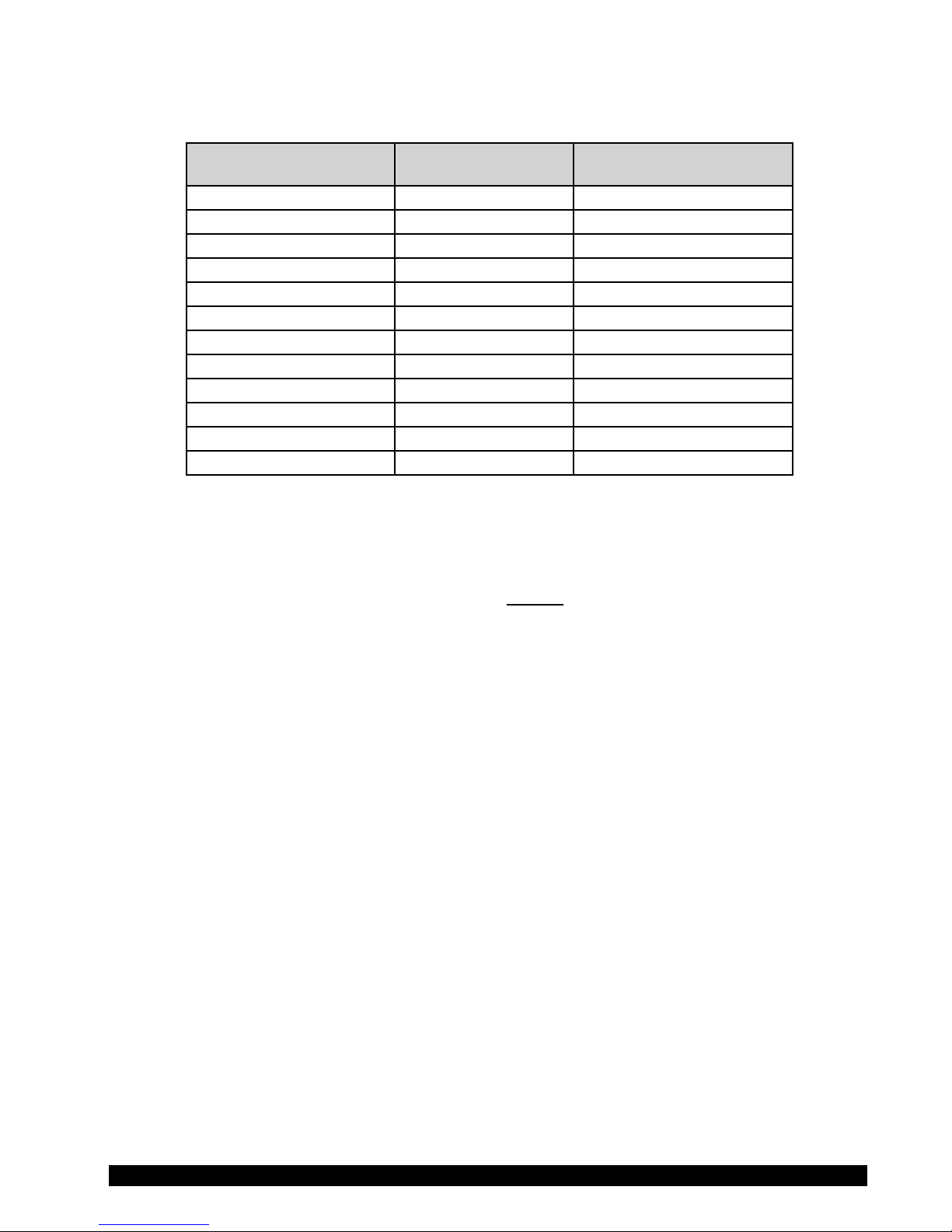
Table D2 lists the model codes and spring torque constants for each Viscometer model.
Table D2
MODEL TK
LVDV-II+ 0.09373 LV
2.5LVDV-II+ 0.2343 2.5 LV
5LVDV-II+ 0.4686 5 LV
1/4 RVDV-II+ 0.25 0.25 RV
1/2 RVDV-II+ 0.5 0.5 RV
RVDV-II+ 1 RV
HADV-II+ 2 HA
2HADV-II+ 4 2 HA
2.5HADV-II+ 5 2.5 HA
HBDV-II+ 8 HB
2HBDV-II+ 16 2 HB
2.5HBDV-II+ 20 2.5 HB
MODEL CODE ON DV-II+
SCREEN
The full scale viscosity range for any DV-II+Pro model and spindle may be calculated using the
equation:
Full Scale Viscosity Range
[cP] = TK * SMC *
10,000
RPM
where:
TK = DV-II+Pro Torque Constant from Table D2
SMC = Spindle Multiplier Constant from Table D1
The Shear Rate calculation is:
Shear Rate (
1
/
) = SRC * RPM
Sec
where:
SRC = Shear Rate Constant from Table D1
Brookeld Engineering Labs., Inc. Page 65 Manual No. M/03-165-D0410
Page 66

Appendix E - Calibration Procedures
The accuracy of the DV-II+Pro is veried using viscosity standard uids which are available
from Brookeld Engineering Laboratories or your local Brookeld agent. Viscosity standards
are Newtonian, and therefore, have the same viscosity regardless of spindle speed (or shear rate).
Viscosity standards, calibrated at 25°C, are shown in Table E1 (Silicone Oils) and Table E2
(Mineral Oils).
For more help you can go to the website,
www.brookeldengineering.com, and download the video.
Container size: For Viscosity Standards < 30,000 cP, use a 600 ml Low Form Grifn Beaker
having a working volume of 500 ml.
For Viscosity Standards
≥ 30,000 cP, use the uid container.
Inside Diameter: 3.25”(8.25cm)
Height: 4.75”(12.1cm)
Note: Container may be larger, but may not be smaller.
Temperature: As stated on the uid standard label: (+/-) 0.1°C
Conditions: The DV-II+Pro should be set according to the operating instructions. The water
bath must be stabilized at test temperature. Viscometers with the letters “LV”
or “RV” in the model designation must have the guard leg attached (see page
65 for more information on the guard leg).
Normal 25ºC Standard Fluids
Viscosity (cP) Viscosity (cP)
5 5,000 HT-30,000
10 12,500 HT-60,000
50 30,000 HT-100,000
100 60,000
500 100,000 **25ºC, 93.3ºC, 149ºC
1,000 Refer to Brookeld catalog for more information
High Temperature Standard Fluids
Three Viscosity/Temperatures**
Table E-1
MINERAL OIL VISCOSITY STANDARD FLUIDS
BEL Part No. Viscosity (cP) 25ºC
B29 29
B200 200
B600 600
B1060 1,060
B2000 2,000
B10200 10,200
B21000 21,000
B73000
B200000 200,000
B360000 360,000
Brookeld Engineering Labs., Inc. Page 66 Manual No. M/03-165-D0410
73,000
Table E-2
Page 67

Brookeld Viscosity Standard Fluid General Information
We recommend that Brookeld Viscosity Standard Fluids be replaced on an annual basis, one
year from date of initial use. These uids are pure silicone and are not subject to change over
time. However, exposure to outside contaminants through normal use requires replacement on
an annual basis. Contamination may occur by the introduction of solvent, standard of different
viscosity or other foreign material.
Viscosity Standard Fluids may be stored under normal laboratory conditions. Disposal should
be in accordance with state, local and federal regulations as specied on the material safety
data sheet.
Brookeld Engineering Laboratories does not recertify Viscosity Standard Fluids. We will
issue duplicate copies of the Certicate of Calibration for any uid within two years of the
purchase date. Brookeld Viscosity Standard Fluids are reusable provided they are not
contaminated. Normal practice for usage in a 600 ml beaker is to return the material from the
beaker back into the bottle. When using smaller volumes in accessories such as Small Sample
Adapter, UL Adapter or Thermosel, the uid is normally discarded.
Calibration Procedure for LV(#1-4) and RV,HA,HB(#1-7) Brookeld Spindles
1) Place the viscosity standard uid (in the proper container) into the water bath.
2) Lower the DV-II+Pro into measurement position (with guard leg if LV or RV series Viscometer
is used).
3) Attach the spindle to the Viscometer. If you are using a disk-shaped spindle, avoid trapping
air bubbles beneath the disk by rst immersing the spindle at an angle, and then connecting it
to the Viscometer.
4) The viscosity standard uid, together with the spindle, should be immersed in the bath for a
minimum of 1 hour, stirring the uid periodically, prior to taking measurements.
5) After 1 hour, check the temperature of the viscosity standard uid with an accurate
thermometer.
6) If the uid is at test temperature (±0.1°
C of the specied temperature, normally 25°C), measure
the viscosity and record the Viscometer reading. Note: The spindle must rotate at least ve (5)
times before readings are taken.
7) The viscosity reading should equal the cP value on the uid standard to within the combined
accuracies of the Viscometer and the viscosity standard (as discussed in the section entitled,
Interpretation of Calibration Test Results) which appears later in this section.
Calibration Procedure for a Small Sample Adapter
Brookeld recommends a two step check. First verify the calibration of the viscometer using
the standard viscometer spindles (LV1-4, RV2-7, HA2-7 and HB2-7 or cone/plate spindles) as
detailed in this appendix. Second verify the calibration of the viscometer using the Small Sample
Adapter. The use of an accessory device may increase the accuracy of measurement associated
with the DV-II+Pro.
Brookeld Engineering Labs., Inc. Page 67 Manual No. M/03-165-D0410
Page 68

When a Small Sample Adapter is used, the water jacket is connected to the water bath and the
water is stabilized at the proper temperature:
1) Put the proper amount of viscosity standard uid into the sample chamber. The amount varies
with each spindle/chamber combination. (Refer to the Small Sample Adapter instruction
manual).
2) Place the sample chamber into the water jacket.
3) Put the spindle into the test uid and attach the extension link, coupling nut and free hanging
spindle (or directly attach the solid shaft spindle) to the DV-II+Pro.
4) Allow 30 minutes for the viscosity standard, sample chamber and spindle to reach test
temperature.
5) Measure the viscosity and record the Viscometer reading.
least ve (5) times before readings are taken.
Note: The spindle must rotate at
Calibration Procedure for a Thermosel System
Brookeld recommends a two step check. First verify the calibration of the viscometer using
the standard viscometer spindles (LV1-4, RV2-7, HA2-7 and HB2-7 or cone/plate spindles) as
detailed in this appendix. Second verify the calibration of the viscometer using the Thermosel.
The use of an accessory device may increase the accuracy of measurement associated with the
DV-II+Pro.
When a Thermosel System is used, the controller stabilizes the Thermo Container at the test
temperature.
1) Put the proper amount of HT viscosity standard uid into the HT-2 sample chamber. The
amount varies with the spindle used. (Refer to the Thermosel instruction manual).
2) Place the sample chamber into the Thermo Container.
3) Put the spindle into the test uid and attach the extension link, coupling nut and free hanging
spindle (or directly attach the solid shaft spindle) to the DV-II+Pro.
4) Allow 30 minutes for the viscosity standard, sample chamber and spindle to reach test
temperature.
5) Measure the viscosity and record the Viscometer reading.
least ve (5) times before readings are taken.
Note: The spindle must rotate at
Calibration Procedure using UL or DIN UL Adapters
Brookeld recommends a two step check. First verify the calibration of the viscometer using
the standard viscometer spindles (LV1-4, RV2-7, HA2-7 and HB2-7 or cone/plate spindles) as
detailed in this appendix. Second verify the calibration of the viscometer using the UL or DIN
Adapters. The use of an accessory device may increase the accuracy of measurement associated
with the DV-II+Pro.
When a UL or DIN UL Adapter is used, the water bath is stabilized at the proper temperature:
1) Put the proper amount of viscosity standard uid into the UL Tube. (Refer to the UL Adapter
instruction manual).
2) Attach the spindle (with extension link and coupling nut) onto the DV-II
3) Attach the tube to the mounting channel.
Brookeld Engineering Labs., Inc. Page 68 Manual No. M/03-165-D0410
+Pro.
Page 69

4) Lower the tube into the water bath reservoir, or if using the ULA-40Y water jacket, connect
the inlet/outlets to the bath external circulating pump.
5) Allow 30 minutes for the viscosity standard, sample chamber and spindle to reach test
temperature.
6) Measure the viscosity and record the Viscometer reading.
least ve (5) times before readings are taken.
Note: The spindle must rotate at
Calibration Procedure using a Helipath Stand and T-Bar Spindles
When a Helipath Stand and T-Bar spindles are used:
1) Remove the T-bar spindle and select a standard LV(#1-4) or RV,HA,HB(#1-7) spindle. Follow
the procedures for LV(#1-4) and RV,HA,HB(#1-7) Brookeld spindles outlined above.
2) T-Bar spindles should not be used for verifying calibration of the DV-II
Viscometer.
Calibration Procedure for Spiral Adapter
Brookeld recommends a two step check. First verify the calibration of the viscometer using
the standard viscometer spindles (LV1-4, RV2-7, HA2-7 and HB2-7 or cone/plate spindles) as
detailed in this appendix. Second verify the calibration of the viscometer using the Spiral Adapter.
The use of an accessory device may increase the accuracy of measurement associated with the
DV-II+Pro.
1) Place the viscosity standard uid (in the proper container) into the water bath.
2) Attach the spindle to the viscometer. Attach chamber (SA-1Y) and clamp to the viscometer.
3) Lower the DV-II
+Pro into measurement position. Operate the viscometer at 50 or 60 RPM
until the chamber is fully ooded.
4) The viscosity standard uid, together with the spindle, should be immersed in the bath for a
minimum of 1 hour, stirring the uid periodically (operate at 50 or 60 RPM periodically), prior
to taking measurements.
5) After 1 hour, check the temperature of the viscosity standard uid with an accurate
thermometer.
6) If the uid is at test temperature (
+/- 0.1°C of the specied temperature, normally 25°C),
measure the viscosity and record the viscometer reading. Note: The spindle must rotate at least
ve (5) times for one minute, whichever is greater before readings are taken.
7) The viscosity reading should equal the cP value on the viscosity uid standard to within the
combined accuracies of the viscometer and the standard (as discussed in the section entitled,
Interpretation of Calibration Test Results). However, instrument accuracy is ±2% of the
maximum viscosity range and not the standard 1%.
+Pro
Calibration Procedure for Cone/Plate Viscometers:
1) Follow the above procedures for mechanically adjusting the setting of the cone spindle to the
plate.
2) Refer to Appendix A, Table A1, and determine the correct sample volume required for the
selected spindle.
Brookeld Engineering Labs., Inc. Page 69 Manual No. M/03-165-D0410
Page 70

3) Select a viscosity standard uid that will give viscosity readings between 10% and 100% of
full scale range. Refer to Appendix B for viscosity ranges of cone spindles. Consult with
Brookeld or an authorized dealer to determine which uid is appropriate.
It is best to use a viscosity standard uid that will be close to the maximum viscosity for a
given cone spindle/speed combination.
Example: LVDV-II+Pro Viscometer, Cone CP-42, Fluid 10
Having a viscosity of 9.7 cP at 25°C
At 60 RPM, the full scale viscosity range is 10.0 cP. Thus, the Viscometer reading should be
97% torque and 9.7 cP viscosity ± 0.197 cP (0.1 cP for the viscometer plus 0.097 cP for the
uid). The accuracy is a combination of Viscometer and uid tolerance (refer to Interpretation
of Calibration Test Results).
4) With the viscometer stopped, remove the sample cup and place the viscosity standard uid into
the cup, waiting 10 minutes for temperature equilibrium.
5) Connect the sample cup to the Viscometer. Allow sufcient time for temperature to reach
equilibrium. Typically 15 minutes is the maximum time that you must wait. Less time is
required if spindle and cup are already at test temperature.
6) Measure the viscosity and record the Viscometer reading in both % torque and centipoise
(cP).
Notes: 1) The spindle must rotate at least ve (5) times before a viscosity reading is
taken.
2) The use of Brookeld Viscosity Standard uids in the range of 5 cP to 5000 cP is
recommended for cone/plate instruments. Please contact Brookeld Engineering
Laboratories or an authorized dealer if your calibration procedure requires more
viscous standards.
3) Select a viscosity standard uid that will give viscosity readings between 10%
and 100% of full scale range. Refer to Appendix B for viscosity ranges of
cone spindles. Do not use a silicone viscosity standard uid with a viscosity
value greater than 5000 cP with a Cone/Plate Viscometer. Brookeld offers a
complete range of mineral oil viscosity standards suitable for use with Cone/Plate
Viscometers as shown in Table E2. Consult with Brookeld or an authorized
dealer to determine which uid is appropriate.
Interpretation of Calibration Test Results:
When verifying the calibration of the DV-II+Pro, the instrument and viscosity standard uid error
must be combined to calculate the total allowable error.
The DV-II+Pro is accurate to (+/-) 1% of the range in use when using spindles LV1-4, RV2-7,
HA2-7 and HB2-7. When using an accessory device with the DV-II+Pro such as Small Sample
Adapter, UL Adapter, Thermosel, Spiral Adapter, and DIN Adapter the accuracy value may be
increased. In general the increase in accuracy will be minimal, however, it could be as much as
1% for a total accuracy of +/- 2% of the range in use.
Brookeld Viscosity Standards Fluids are accurate to (+/-) 1% of their stated value.
Brookeld Engineering Labs., Inc. Page 70 Manual No. M/03-165-D0410
Page 71

Example: Calculate the acceptable range of viscosity using RVDV-II+Pro with RV-3 Spindle
at 2 RPM; Brookeld Standard Fluid 12,500 with a viscosity of 12,257 cP at 25°C:
1) Calculate full scale viscosity range using the equation:
Full Scale Viscosity Range [cP] = TK * SMC *
10,000
RPM
Where:
TK - 1.0 from Table D2
SMC = 10 from Table D1
Full Scale Viscosity Range
10 * 10,000
1
*
2
=
50,000 cP
The viscosity is accurate to (+/-) 500 cP (which is 1% of 50,000)
2) The viscosity standard uid is 12,257 cP. Its accuracy is (+/-)1% of 12,257 or
(+/-)122.57 cP.
3) Total allowable error is (122.57 + 500) cP = (+/-) 622.57 cP.
4) Therefore, any viscosity reading between 11,634.4 and 12,879.6 cP indicates that the Viscometer
is operating correctly. Any reading outside these limits may indicate a Viscometer problem.
Contact the Brookeld technical sales department or your local Brookeld dealer/distributor
with test results to determine the nature of the problem.
Example: Calculate the acceptable accuracy for viscosity measurement using LVDV-II+ Pro
with SC4-21 spindle in Small Sample Adapter at 6, 12, and 30 RPM. Brookeld
viscosity standard uid 100 cPs has an actual value of 101.5 cP at 25ºC.
1) Calculate the full scale viscosity range either by using the Spindle Range Coefcient in
Appendix B of More Solutions to Sticky Problems or by using the Auto Range button on
your viscometer.
The Spindle Range Coefcient for the 21 spindle on an LV Torque instrument is 4,688.
At 6 RPM, the Full Scale Range (FSR) viscosity is 781 cP. Allow +/- 1% for the viscometer
and +/- 1% for the Small Sample Adapter. Total allowable accuracy is:
+/- 2% x 781 cP = +/- 15.6 cP
A similar calculation at 12 RPM gives FSR = 391 cP: +/- 2% x 391 cP = +/- 7.8 cP
A similar calculation at 30 RPM gives FSR = 156 cP: +/- 2% x 156 cP = +/- 3.1 cP
2) The Viscosity Standard Fluid is 101.5 cP. Its accuracy is:
+/- 1% x 101.5 cP = +/- 1.015 cP or roughly +/- 1.0 cP for further calculations.
3) Total accuracy is the sum of the values n (1) and (2):
At 6 RPM, accuracy is: 15.6 cP + 1.0 cP = +/- 16.6 cP
At 12 RPM, accuracy is: 7.8 cP + 1.0 cP = +/- 9.8 cP
At 30 RPM, accuracy is: 3.1 cP = 1.0 cP = +/- 4.1 cP
Brookeld Engineering Labs., Inc. Page 71 Manual No. M/03-165-D0410
Page 72

4) Therefore, at each speed, the acceptable windows within which the measured viscosity value
must lie is calculated relative to the viscosity value of the standard:
At 6 RPM: 84.9 cP to 118.1 cP
At 12 RPM: 91.7 cP to 111.3 cP
At 30 RPM: 97.4 cP to 105.6 cP
If your measured values fall outside of these windows, contact Brookeld or your authorized
dealer to discuss your results and determine whether your instrument is out of calibration.
Brookeld Engineering Labs., Inc. Page 72 Manual No. M/03-165-D0410
Page 73

Appendix F - The Brookeld Guardleg
The guard leg was originally designed to protect the spindle during use. The rst applications of the
Brookeld Viscometer included hand held operation while measuring uids in a 55-gallon drum.
It is clear that under those conditions the potential for damage to the spindle was great. Original
construction included a sleeve that protected the spindle from side impact. Early RV guard legs
attached to the dial housing and LV guard legs attached to the bottom of the pivot cup with a twist
and lock mechanism.
The current guard leg is a band of metal in the shape of the letter U with a bracket at the top that
attaches to the pivot cup of a Brookeld Viscometer/Rheometer. Because it must attach to the pivot
cup, the guard leg cannot be used with a Cone/Plate instrument. A guard leg is supplied with all LV
and RV series instruments, but not with the HA or HB series. It’s shape (shown in Figure F-1) is
designed to accommodate the spindles of the appropriate spindle set; therefore, the RV guard leg is
wider than the LV due to the large diameter of the RV #1 spindle. They are not interchangeable.
The calibration of the Brookeld Viscometer/Rheometer is determined using a 600 mL Low Form
Grifn Beaker. The calibration of LV and RV series instruments includes the guard leg. The beaker
wall (for HA/HB instruments) or the guard leg (for LV/RV instruments) dene what is called the
“outer boundary” of the measurement. The spindle factors for the LV, RV, and HA/HB spindles
were developed with the above boundary conditions. The spindle factors are used to convert the
instrument torque (expressed as the dial reading or %Torque value) into centipoise. Theoretically,
if measurements are made with different boundary conditions, e.g., without the guard leg or in a
container other than 600 ml beaker, then the spindle factors found on the Factor Finder cannot be
used to accurately calculate an absolute viscosity. Changing the boundary conditions does not
change the viscosity of the uid, but it does change how the instrument torque is converted to
centipoise. Without changing the spindle factor to suit the new boundary conditions, the calculation
from instrument torque to viscosity will be incorrect.
Practically speaking, the guard leg has the greatest effect when used with the #1 & #2 spindles of
the LV and RV spindle sets (Note: RV/HA/HB #1 spindle is not included in standard spindle set).
Any other LV (#3 & #4) or RV (#3 - #7) spindle can be used in a 600 mL beaker with or without
the guard leg to produce correct results. The HA and HB series Viscometers/Rheometers are not
supplied with guard legs in order to reduce the potential problems when measuring high viscosity
materials. HA/HB spindles #3 through #7 are identical to those spindle numbers in the RV spindle
set. The HA/HB #1 & #2 have slightly different dimensions than the corresponding RV spindles.
This dimensional difference allows the factors between the RV and HA/HB #1 spindles to
follow the same ratios as the instrument torque even though the boundary conditions are different.
The recommended procedures of using a 600 mL beaker and the guard leg are difcult for some
customers to follow. The guard leg is one more item to clean. In some applications the 500 ml
of test uid required to immerse the spindles in a 600 mL beaker is not available. In practice, a
smaller vessel may be used and the guard leg is removed. The Brookeld Viscometer/Rheometer
will produce an accurate and repeatable torque reading under any measurement circumstance.
However, the conversion of this torque reading to centipoise will only be correct if the factor used
was developed for those specic conditions. Brookeld has outlined a method for recalibrating
a Brookeld Viscometer/Rheometer to any measurement circumstance in More Solutions to
Sticky Problems. It is important to note that for many viscometer users the true viscosity is not
Brookeld Engineering Labs., Inc. Page 73 Manual No. M/03-165-D0410
Page 74

as important as a repeatable day to day value. This repeatable value can be obtained without any
B-21KY
Guard Leg
B-20KY
Guard Leg
5 7/8
5 5/32
For RV Torque
For LV Torque
3 3/16
1 7/16
special effort for any measurement circumstance. But, it should be known that this type of torque
reading will not convert into a correct centipoise value when using a Brookeld factor if the
boundary conditions are not those specied by Brookeld.
The guard leg is a part of the calibration check of the Brookeld LV and RV series Viscometer/
Rheometer. Our customers should be aware of its existence, its purpose and the effect that it
may have on data. With this knowledge, the viscometer user may make modications to the
recommended method of operation to suit their needs.
Figure F-1
Brookeld Engineering Labs., Inc. Page 74 Manual No. M/03-165-D0410
Page 75

Appendix G - Speed Sets
The following speed sets and custom speeds are selectable from the SETUP menu option. All
speeds are in units of RPM.
Interleave
Speed From
0.0
0.3 LVT
0.5 RVT
0.6 LVT
1.0 RVT
1.5 LVT
2.0 RVF
2.5 RVT
3.0 LVT
4.0 RVF
5.0 RVT
6.0 LVT
10.0 RVT
12.0 LVT
20.0 RVT
30.0 LVT
50.0 TVT
60.0 LVT
100.0 RVT
Speed From
OR
100.0 RVT
Sequential
0.0
0.3 LVT
0.6 LVT
1.5 LVT
3.0 LVT
6.0 LVT
12.0 LVT
30.0 LVT
60.0 LVT
0.0
0.5 RVT
1.0 RVT
2.0 RVF
2.5 RVT
4.0 RVF
5.0 RVT
10.0 RVT
20.0 RVT
50.0 RVT
Custom
Speed Speed Speed
0.0 3.0 100.0
0.01 4.0 105.0
0.03 5.0 120.0
0.05 6.0 135.0
0.07 7.5 140.0
0.09 8.0 150.0
OR
0.1 10.0 160.0
0.2 12.0 180.0
0.3 15.0 200.0
0.4 17.0
0.5 20.0
0.6 22.0
0.7 25.0
0.8 30.0
0.9 35.0
1.0 40.0
1.1 45.0
1.2 50.0
1.4 60.0
1.5 70.0
1.8 75.0
2.0 80.0
2.5 90.0
The DV-II+Pro has the sequential speed set installed at Brookeld prior to shipment.
Note: Additional speeds are available when using Rheocalc32 Software (DV-II+Pro
in external mode - see section II.9).
Brookeld Engineering Labs., Inc. Page 75 Manual No. M/03-165-D0410
The DV-II+Pro can be programmed to select up to 18 of the
above speeds for use at any one
time. Speed 0.0 is automatically
included as the 19th speed.
Page 76

Appendix H - Communications
When using the Brookeld Computer Cable (Brookeld part # DVP-80), the DV-II+Pro will
output a data string at a rate of approximately 3 times per second. When using the Brookeld
Printer Cable (Brookeld Part No. DVP-81), the output rate is 1.0 times per second. The DVII+Pro uses the following RS-232 parameters to output these strings:
Baud Rate 9600
Data Bits 8
Stop Bits 1
Parity None
Handshake None
The following formulas should be used to calculate and display the Viscometer data after each
packet of data is obtained from the DV-II+Pro.
Viscosity (cP) = 100 * TK * SMC * Torque
RPM
Shear Rate (
Shear Stress (
1
/
) = RPM * SRC
Sec
Dynes
2
/
) = TK * SMC * SRC * Torque
Cm
Where:
RPM = Current Viscometer spindle speed in RPM
TK = Viscometer torque constant from Appendix D, Table D2.
SMC = Current spindle multiplier constant from Appendix D, Table D1.
SRC = Current spindle shear rate constant from Appendix D, Table D1.
Torque = Current Viscometer torque (%) expressed as a number between 0 and 100.
As an example, consider an LV Viscometer using an SC4-31 spindle, running at 30 RPM and
currently displaying a Torque of 62.3 (%). First we list all of the given data and include model
and spindle constants from Appendix D, Tables D1 and D2:
RPM = 30 from the example statement.
TK = 0.09373 from Appendix D for an LV Viscometer.
SMC = 32.0 from Appendix D for a type SC4-31 spindle.
SRC = 0.34 from Appendix D for a type SC4-31 spindle.
Torque = 62.3 from the example statement.
Applying this data to the above equations yields:
Viscosity (cP) = 100 * TK * SMC * Torque
RPM
= 100 * 0.09373 * 32.0 * 62.3
30
= 622.9 cP
Shear Rate (1/
) = RPM * SRC
Sec
= 30 * 0.34
=
Brookeld Engineering Labs., Inc. Page 76 Manual No. M/03-165-D0410
10.2
1
/
Sec
Page 77

Shear Stress (
Dynes
2
/
) = TK * SMC * SRC * Torque
Cm
= 0.09373 * 32.0 * 0.34 * 62.3
= 63.5
Dynes
/
2
Cm
Brookeld Engineering Labs., Inc. Page 77 Manual No. M/03-165-D0410
Page 78

2
3
4
5
6
7
8
9
1
No Connection
Transmit Data (TxD)
No Connection
High Speed Print
(Note 1)
High Speed Print
(Note 1)
Serial Ground
Analog Ground
Analog % Torque
(Note 2)
Analog Temperature
(Note 3)
DV-II+
Serial and Analog Outputs
Notes:
1. Placing a jumper across pins 4 and 9 causes the DV- II+ to output printer
data at a 3 line-per
-second rate. No jumper across pins 4 and 9 retains the
once-per
-second printer output rate.
2. This is a 0-1 volt d.c. output where 0 volts corresponds to 0% torque and
1 volt corresponds to 100 % torque with a resolution of 1 millivolt (0.1%).
3. This is a 0-3.75 volt d.c. output where 0 volts corresponds to -100
°
C and
3.75 volts corresponds to +275 C with a resolution of 1 millivolt (0.1°C).
°
Analog Output:
Figure H1
The analog outputs for temperature and % torque are accessed from the 9-pin connector located
on the rear panel of the DV-II+Pro. The pin connections are shown in Figure G1.
The output cable (Part No. DVP-96Y) connections are:
Red Wire: Temperature Output
Black Wire: Temperature Ground
White Wire: % Torque Output
Green Wire: % Torque Ground
Note: Please contact Brookeld Engineering Laboratories or your local dealer/
distributor for purchase of the DVP-96Y analog output cable.
Brookeld Engineering Labs., Inc. Page 78 Manual No. M/03-165-D0410
Page 79

Appendix I - Model S Laboratory Stand
Å
CLAMP ASSEMBLY
NOTE: “FRONT” FACES TOWARD YOU.
BROOKFIELD
LABORATORY
VISCOMETER
TENSION
SCREW
Ç
É
Ñ
Ö
ITEM PART # DESCRIPTION QTY.
1 VS-CRA-14S 14” UPRIGHT ROD AND CLAMP ASSEMBLY 1
VS-CRA-18S 18” UPRIGHT ROD AND CLAMP ASSEMBLY Optional
2 VS-2Y BASE, includes 2 VS-3 leveling screws 1
3 VS-3 LEVELING SCREW available separately or in assembly above 2
4 50S311832S01B SCREW 5/16 X 1” Hex Head 1
5 502028071S33B FLAT WASHER 5/16 X 7/8 X .071 1
Brookeld Engineering Labs., Inc. Page 79 Manual No. M/03-165-D0410
Page 80

Unpacking
Check carefully to see that all the components are received with no concealed damage.
1 Base, VS-2, with 2 Leveling Screws, VS-3, packed in a cardboard carton
1 Upright Rod with attached Clamp Assembly
Assembly (Refer to Figure H1)
1. Remove the base assembly from the carton.
2. Remove the screw and washer from the upright rod. Place the rod and clamp assembly into the
hole in the top of the base.
Note: The “Front” designation on the clamp assembly should face
toward you.
3. Rotate the rod/clamp assembly slightly until the slot on the bottom of the rod intersects the pin
located in the base.
4. While holding the rod and base together, insert the slotted screw and washer as shown and tighten
securely.
Viscometer Mounting
Insert the Viscometer mounting rod into the hole (with the cut-away slot) in the clamp assembly.
Adjust the instrument level until the bubble is centered from right to left and tighten the clamp knob
(clockwise). Use the leveling screws to “ne” adjust the viscometer level.
Note: If the Digital Viscometer cannot be leveled, check to insure that the rod is
installed with the gear rack facing forward.
Caution: Do not tighten the clamp knob unless the viscometer mounting rod is
inserted in the clamp assembly.
Operation
Rotate the UP/DOWN knob to raise or lower the viscometer. Adjust the tension screw if the UP/
DOWN movement of the viscometer head is not acceptable, i.e. too lose or too difcult.
Brookeld Engineering Labs., Inc. Page 80 Manual No. M/03-165-D0410
Page 81

Appendix J - DVE-50A Probe Clip
RTD Probe
Hole
Squeeze Here when
installing RTD
Temperature probe
6
0
0 ml
500
ml
400
300
200
100
USA
No. 14000
600 ml Low Form
Griffin Beaker
DVE–50
Probe Clip
RTD Temperature Probe
LV Guard Leg
Assembly B-20KY
Probe Clip
DVE-50
R TD Temperature
Probe
Probe Clip DVE-50A is supplied with all model DV-II+Pro Viscometers, DV-III
Rheometers, and Digital Temperature Indicators. It is used to attach the RTD temperature
probe to the LV Guard Leg (Part No. B-20Y) or 600 ml low form Grifn beaker. Figure J1
is a view of the Probe Clip, showing the hole into which the RTD probe is inserted, and the
slot which ts onto the LV guard leg. When inserting the RTD probe into the Probe Clip,
the upper part of the Clip is compressed by squeezing the points shown in Figure J1.
Note: All Viscometer/Rheometer models — except LV — use the Probe Clip as
shown in Figure J3.
Figure J1
Figure J2 shows the Probe Clip (with RTD temperature probe installed) mounted on the LV
guard leg.
Figure J3 shows the Probe Clip mounted in a 600 ml low form Grifn beaker. This
mounting may be used with LV, RV, HA and HB series instruments.
Note: The RTD probe must be parallel to the beaker wall so as not to interfere with the
viscosity measurement.
Figure J2
Figure J3
Brookeld Engineering Labs., Inc. Page 81 Manual No. M/03-165-D0410
Page 82

Appendix K - Fault Diagnosis and Troubleshooting
Listed are some of the more common problems that you may encounter while using your
Viscometer.
❏ Spindle Does Not Rotate
✓ Make sure the viscometer is plugged in.
✓ Check the voltage rating on your viscometer (115, 220V); it must match the wall voltage.
✓ Make sure the motor is ON and the desired rpm is selected.
❏ Spindle Wobbles When Rotating or Looks Bent
✓ Make sure the spindle is tightened securely to the viscometer coupling.
✓ Check the straightness of all other spindles; replace if bent.
✓ Inspect viscometer coupling and spindle coupling mating areas and threads for dirt; clean
threads on spindle coupling with a 3/56 left-hand tap.
✓ Inspect threads for wear; if the threads are worn, the unit needs service (see Appendix M).
Check to see if spindles rotate eccentrically or wobble. There is an allowable runout of 1/32inch in each direction (1/16-inch total) when measured from the bottom of the spindle rotating
in air.
✓ Check to see if the viscometer coupling appears bent; if so, the unit is in need of service (see
Appendix M, “How to Return Your Viscometer”).
If you continue to experience problems with your viscometer, follow this troubleshooting section to
help isolate potential problems.
❏ Perform an Oscillation Check*
✓ Remove the spindle and turn the motor OFF; select display to % torque mode.
✓ Gently push up on the viscometer coupling.
✓ Turn the coupling until the digital display reads 10-15 on the % display.
✓ Gently let go of the coupling.
✓ Watch the digital display; you should see a “run” of numbers next to the %; the “run” of
numbers should ultimately stop at 0.0 (+/- 0.1).
If the digital display does not return to ZERO, the unit is in need of service (see Appendix M,
“How to Return Your Viscometer”).
* This procedure does not apply to instruments with ball bearing suspension.
Brookeld Engineering Labs., Inc. Page 82 Manual No. M/03-165-D0410
Page 83

❏ Inaccurate Readings
✓ Verify spindle, speed and model selection.
✓ If % readings are under-range (less than 10%), the display will ash; change spindle and/or
speed.
✓ “EEE” on the digital display means the unit is over-range (greater than 100%); reduce speed
and/or change spindle.
✓ Verify test parameters: temperature, container, volume, method. Refer to:
• “More Solutions to Sticky Problems”, Section III
• “DV-II+Pro Viscometer Operating Instructions, Appendix C, “Variables in
Viscosity Measurements.
✓ Perform a calibration check; follow the instructions in Appendix E.
✓ Verify tolerances are calculated correctly.
✓ Verify the calibration check procedures were followed exactly.
If the unit is found to be out of tolerance, the unit may be in need of service. See Appendix M
for details on “How to Return Your Viscometer”.
❏ Viscometer Will Not Return to Zero
✓ Viscometer is not level
• Check with spindle out of the sample
• Adjust the laboratory stand
✓ Pivot point or jewel bearing faulty
• Perform calibration check
• Contact Brookeld Engineering Laboratories, Inc. or your Brookeld dealer for repair
❏ Display Reading Will Not Stabilize
✓ Special characteristic of sample uid. There is no problem with the viscometer.
• Refer to Appendix C
✓ Check for erratic spindle rotation.
• Verify power supply
• Contact Brookeld Engineering Laboratories, Inc. or your Brookeld dealer for repair
✓ Bent spindle or spindle coupling.
• Contact Brookeld Engineering Laboratories, Inc. or your Brookeld dealer for repair
✓ Temperature uctuation in sample uid
• Use temperature bath control.
Brookeld Engineering Labs., Inc. Page 83 Manual No. M/03-165-D0410
Page 84

❏ No Recorder Response
✓ Be Sure the viscometer is not at ZERO reading.
✓ Be sure the recorder is ON and not on STANDBY.
✓ Verify the range settings.
✓ Check cable leads for clean connection.
❏ Recorder Pen Moves in Wrong Direction
✓ Output polarity reversed
• Reverse leads
❏ Viscometer Will Not Communicate with PC
✓ Check the comm port and make sure the correct port is being utilized.
✓ Check the interconnecting cable for proper installation
✓ Check the Options menu and make sure the PC PROG is set to either “ON” or “OFF” in
accordance with the operating instructions for the program/procedure in use.
If the above do not rectify the problem, do the following:
✓ Shut off viscometer
✓ Attach printer.
✓ Press and hold the MOTOR ON/OFF and ENTER/AUTORANGE keys simulanteously while
turning the viscometer power on. Figure K1 appears on the viscometer display.
VISCOMETER SETUP
ENTER TO START
Figure K1
✓ Press ENTER/AUTORANGE key and Figure J2 appears.
PRINT PARAM RAM?
NO#$ THEN ENTER
"
t
PRINT PARAM RAM?
YES#$ THEN ENTER
Brookeld Engineering Labs., Inc. Page 84 Manual No. M/03-165-D0410
Figure K2
Page 85

✓ Scroll to YES and press the ENTER/AUTORANGE key. Figure K3 appears.
READY PRINTER
ENTER TO START
Figure K3
✓ Press ENTER/AUTORANGE. Information similar to Figure K4 will appear on your
printer output.
Timed Stop Minutes 01
Seconds 30
RPM 50
Time to Torque Torque % 60
RPM 50
Print Interval Minutes 00
Seconds 05
Printer Port Parallel or Serial Parallel
Last Spindle used 05
Special Spindle AA SMC 0000.000
Special Spindle AA SRC 00.000
Special Spindle BB SMC 0000.000
Special Spindle BB SRC 00.000
Special Spindle CC SMC 0000.000
Special Spindle CC SRC 00.000
Special Spindle DD SMC 0000.000
Special Spindle DD SRC 00.000
Display Units CGS
Temperature Scale C
Speed Set INTERLEAVE
Viscometer Model RV
Last BEVIS Program 1
Raw Temps 2E0C 00FE
Torque Scale E19F
✓ Call Brookeld to review the information on your printer output.
✓ Figure K5 next appears on the viscometer display. Turn the viscometer power off.
Brookeld Engineering Labs., Inc. Page 85 Manual No. M/03-165-D0410
Figure K4
SETUP COMPLETE
TURN POWER OFF
Figure K5
Page 86

Appendix L - Instrument Dimensions
13 21/64”
[33.9 cm]
7 15/16”
[20.2 cm]
4 9/64”
[10.5 cm]
3 3/16”
[8.1 cm]
6 63/64”
[17.7 cm]
15 41/64”
[39.7 cm]
7 63/64”
[20.3 cm]
16 31/64”
[41.9 cm]
11 3/16”
[28.4 cm]
VS-2Y
LAB STAND BASE ASSEMBLY
B-21Y
RV GUARD LEG
ASSEMBLY
DV-II+ PRO VISCOMETER
Brookeld Engineering Labs., Inc. Page 86 Manual No. M/03-165-D0410
Page 87

Appendix M - Warranty Repair and Service
Warranty
Brookeld Viscometers are guaranteed for one year from date of purchase against defects in
materials and workmanship. They are certied against primary viscosity standards traceable to
the National Institute of Standards and Technology (NIST). The Viscometer must be returned
to Brookeld Engineering Laboratories, Inc. or the Brookeld dealer from whom it was
purchased for no charge warranty service. Transportation is at the purchaser’s expense. The
Viscometer should be shipped in its carrying case together with all spindles originally provided
with the instrument. If returning to Brookeld please contact us for a return authorization
number prior to shipping.
For a copy of the Repair Return Form, go to the Brookeld website,
www.brookeldengineering.com
For repair or service in the United States return to:
Brookeld Engineering Laboratories, Inc.
11 Commerce Boulevard
Middleboro, MA 02346 U.S.A.
Telephone: (508) 946-6200 FAX: (508) 923-5009
www.brookeldengineering.com
For repair or service outside the United States consult Brookeld Engineering Laboratories, Inc. or the
dealer from whom you purchased the instrument.
For repair or service in the United Kingdom return to:
Brookeld Viscometers Limited
Brookeld Technical Centre
Stadium Way
Harlow, Essex CM19 5GX, England
Telephone: (44) 1279/451774 FAX: (44) 1279/451775
www.brookeld.co.uk
For repair or service in Germany return to:
Brookeld Engineering Laboratories Vertriebs GmbH
Hauptstrasse 18
D-73547 Lorch, Germany
Telephone: (49) 7172/927100 FAX: (49) 7172/927105
www.brookeld-gmbh.de
For repair or service in China return to:
Guangzhou Brookeld Viscometers and Texture Instruments Service Company Ltd.
Suite 905, South Tower, Xindacheng Plaza
193 Guangzhou Da Dao Bei, Yuexiu District
Guangzhou, 510075 P. R. China
Telephone: (86) 20/3760-0548 FAX: (86) 20/3760-0548
On-site service at your facility is also available from Brookeld. Please contact our Service
Department in the United States, United Kingdom, Germany or China for details.
Brookeld Engineering Labs., Inc. Page 87 Manual No. M/03-165-D0410
www.brookeld.com.cn
Page 88

BROOKFIELD ENGINEERING LABORATORIES, INC. • 11 Commerce Blvd. • Middleboro, MA 02346 • TEL: 508-946-6200 or 800-628-8139 FAX: 508-946-6262 • www.brook eldengineering.com • VTR1207
VISCOSITY TEST REPORT
DATE: FOR:
BY:
TEST INFORMATION:
SAMPLE MODEL SPINDLE RP
M
DIAL READING
% TORQUE
FACTOR
VISCOSITY
cP
SHEAR
RATE
TEMP °C TIME NOTES
CO
NCL
USIONS:
This tear-o sheet is a typical example of recorded test data. Please photocopy and retain this
template so that additional copies may be made as needed.
Brookeld Engineering Labs., Inc. Page 88 Manual No. M/03-165-D0410
 Loading...