


BV9973

To ensure safety while driving
and to comply with laws,
drivers should not watch video or
operate the video device while driving.

-1-
Content
Precaution......................................
Safety Information.........................
Disc Note.......................................
Installation ....................................
Electric Connection ......................
Remote Control ............................
Basic Operation ............................
Loading/Ejecting a DISC .................
Open/Close Monitor and Angle
Adjustment......................... ........
Main Menu Operation......................
Setting animation...........................
Setting disc....................................
Setting radio...................................
Setting wallpaper............ ................
Version about..................................
Setting time.......... .........................
Setting audio mode.........................
Setting video mode.........................
Setting OSD language....................
Setting illumination
color.................
TFT display calibration. ..................
Rear View Camera ........................
Control Panel ................................
Unit keys ........................................
Radio Operation............................
Listening to the radio ......................
Storing and Listening to a memory
station ........................................
18
18
20
21
21
22
24
24
24
24
24
25
25
25
25
26
27
28
28
29
30
31
32
33
2
3
4
5
7
8
10
10
10
11
11
12
12
12
12
12
12
13
13
13
13
13
14
14
17
17
17
Automatic Memory Storing &
Program Scanning.......................
RDS function..................................
Media Operation.............................
Basic Operation ..............................
Selecting Play Mode ........................
On-Screen Display Function .............
Digital
Video Special Function........
Multi-Subtitle Language function.......
Multi-audio language Function..........
Multi-angle Function........................
Tit l e menu function ..........................
A-B Repeat function.........................
Program function.............................
Step function..................................
Slow speed function........................
AUX Operation ...............................
AV Operation..................................
USB Operation ...............................
Card Operation ..............................
SWC Operation..............................
Parental Control............................
Region Code..................................
Specification .................................
Troubleshooting.............................

-2-
Precaution
THANK YOU FOR PURCHASING PLAYER .
Before operating the unit, read this manual thoroughly and keep it handy
for future reference .
To avoid injury or accident , read the following precautions before
installing and operating the unit .
A BOSS AUDIO MULTIMEDIA
ABOUT THE LIQUID CRYSTAL DISPLAY (LCD) PANEL
Do not press on the LCD panel on the unit as doing so can distort the
picture or cause a malfunction . The picture may become unclear , or the
LCD panel may be damaged .
NOTES ON CLEANING
-Clean the LCD panel with a slightly damp soft cloth.
-Do not use solvents such as benzine, thinner, commercially available
cleaners or antistatic spray .
- Do not use alcohol to clean the screen .
If your car was parked in a cold or hot place, the picture may not be clear .
The monitor is not damaged . The picture will become clear the temper-
ature in your car becomes normal .
DO NOT install any receiver in locations where;
- it may obstruct the steering wheel and gearshift lever operations, as this
may result in a traffic accident.
- it may obstruct the operation of safety devices such as air bags, as this
may result in a fatal accident.
- it may obstruct visibility.
DO NOT operate any receiver while manipulating the steering wheel, as
this may result in a traffic accident.
The driver must not watch the monitor while driving.
IF THE DRIVER watches the monitor while driving, it may lead to
carelessness and cause an accident.
IF YOU NEED to operate the receive while driving, be sure to look ahead
carefully or you may be involved in a traffic accident.
IF THE PARKIN G BRAKE is not engaged.“ ParkingBrake” flashes on the
monitor, and no playback picture will be shown.
- This warning appears only when the parking brake wire is connected to
the parking brake system built in the car ( refer to the electric connection)
ON INSTALLATION

-3-
Safety Information
CAUTION:
THIS DIGITAL VIDEO PLAYER IS A CLASS I LASER PRODUCT. HOWEVER
THIS DIGITAL VIDEO PLAYER USES A VISIBLE/INVISIBLE LASER BEAM
WHICH COULD CAUSE .
HAZARDOUS RADIATION EXPOSURE IF DIRECTED. BE SURE TO OPERATE
THE DIGITAL VIDEO PLAYER CORRECTLY AS INSTRUCTED.
USE OF CONTROLS OR ADJUSTMENTS OR PERFORMANCE OF
PROCEDURES OTHER THAN THOSE SPECIFIED HEREIN MAY RESULT IN
HAZARDOUS RADIATION EXPOSURE.DO NOT OPEN COVERS AND DO NOT
REPAIR YOURSELF. REFER SERVICING TO QUALIFIED PERSONNEL.
WARNING:
TO REDUCE THE RISK OF FIRE OR ELECTRIC SHOCK, DO NOT EXPOSE THIS
EQUIPMENT TO RAIN OR MOISTURE.
TO REDUCE THE RISK OF FIRE OR ELECTRIC SHOCK, AND ANNOYING
INTERFERENCE, USE ONLY THE RECOMMENDED ACCESSORIES.
THIS DEVICE
IS INTENDED FOR CONTINUOUS OPERATION.
This product incorporates copyright protection technology that is protected
by method claims of certain U.S. Patents and other intellectual property rights
owned by Macrovision Corporation and other rights owners.Use of this
copyright protection technology must be authorized by
Macro vision Corporation,
and is intended for home and other limited viewing uses only unless
otherwise authorized by Macrovision Corporation. Reverse engineering or
disassembly is prohibited.
REGION MANAGEMENT INFORMATION:
This Digital Video Player is designed and manufactured to respond to the Region
Management Information that is recorded on a Digital Vid eo disc. If the Region
number described on the Digital Video disc does not correspond to the Region
number of this
Digital Video Player, this Digital Video Player cannot play this disc.
-4-
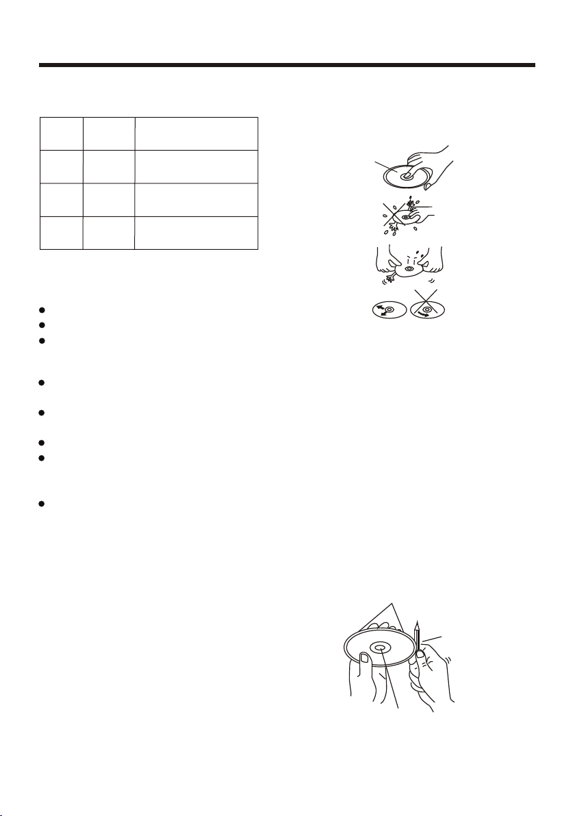
Disc Note
Preparing New Discs with Rough
Spots
A new disc may have rough edges on
its inside and outside edges. If a disc
with rough edges is used, the proper
setting will not be performed and the
player will not play the disc. Therefore,
remove the rough edges in advance
by using a ball point pen or pencil
as
shown on the right. To remove the
rough edges, press the side of the pen
or pencil against the inside and outside
edges of the disc.
Rough spots
on
outside edge
Ball point pen
or pencil
Rough spots
on inside
edge
Do not touch
the
underside
of the disc
Do not
bend
Wipe the disc from
center
toward the outside
edge
Label side
up
Disc Cleaning
Use a dry soft cloth to wipe the surface.
If the disc is quite dirty, use a soft cloth
slightly moistured with isopropyl (rubbing)
alcohol. Never use solvents such as
benzine, thinner or conventional record
cleaners as they may mar the surface of
the disc.
Handling and Cleaning
Dirt, dust, scratches and warping disc
will cause misoperation.
Do not place stickers or make
scratches on discs.
Do not warp discs.
A disc should always be kept in its
case when not in use to prevent from
damaging.
Do
not place discs in the following
places:
1.Direct sunlight
2.Dirty, dusty and damp areas
3.Near car heaters
4.On the seats or dashboard
Discs which cannot be played
with this player
Digital Video-RAM
CDV
CDG
Note:
A disc may become somewhat scratched
(although not enough to make it
unusable) depending on your handle it
and conditions in the usage environment.
Note these scratches are not an
indication of any problem with the player.
Disc formats supported by this
player
Digital
Video
VCD
CD
MP3
Audio and Vi de o
Disc size 12 cm
Audio and Vi de o
Disc size 12 cm
Audio
Disc size 12 cm
Audio
Disc size 12 cm
Digital
Video
VCD
CD
MP3

NOTES:
Choose the mounting location where the unit will not interfere with the normal
driving function of the driver.
Before finally installing the unit, connect the wiring temporarily and make sure
it is all connected up properly and the unit and the
system work properly.
Use only the parts included with the unit to ensure proper installation. The use
of unauthorized parts can cause malfunctions.
Consult with your nearest dealer if installation requires the drilling of holes or
other modifications of
the vehicle.
Install the unit where it does not get in the driver s way and cannot injure the
passenger if there is a sudden stop, like an emergency stop.
If installation angle exceeds 30 from horizontal, the unit might not give
its
optimum performance.
Avoid installing the unit where it would be subject to high temperature, such
as from direct sunlight, or from hot air, from the heater, or where it would be
subject to dust, dirt
or excessive vibration.
DIN FRONT/REAR-MOUNT
This unit can be properly installed either from "Front"(conventional DIN
Front-mount) or "Rear"(DIN Rear-mount installation, utilizing threaded
screw holes at the sides of the unit chassis). For details, refer to the following
illustrated installation methods.
'
Installation
-5-
30

Installation
-6-
Installing the unit
If you want to take the CHASSIS out of the SLIDE BRACKET HOUSING, first
remove the PLASTIC COVER on both sides , then insert the two KEY PLATES
into the left and the right sides of the chassis as illustrated above.
KEY PLATE
PLASTIC TRIM OUT
KEY PLATE
DASH BOARD
METAL MOUNTING
STRAP
HEX NUT
SPRING WASH ER
PLAIN WASH ER
TAPPING SCREW
CONSOLE
SLIDE BRACKET
HOUSING
HEX BOLT
SCREWDRIVER
TAB S
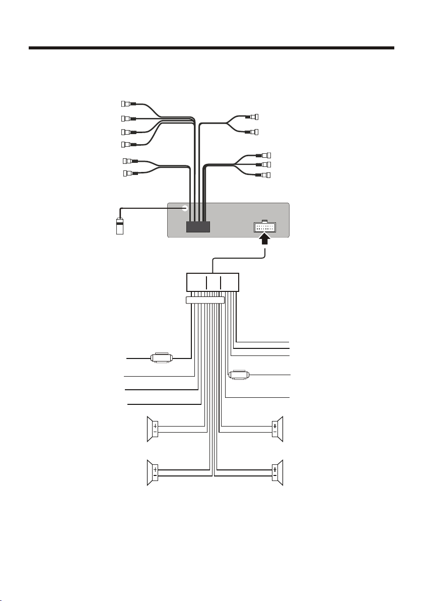
Electric Connection
-7-
WIRING CONNECTION
Note:
the ground connection cable (parking brake B-) must be connected in order for
pictures to be played back to the monitor. If the cable has not been correctly
connected, appears on the monitor. warning message
VIOLET/WHITE
(B+)12V
REAR CAMERA SWITCH
(B-)PARKING BRAKE
GREY
GREY/BLACK
FRONT
RCH SPK.
VIOLET
VIOLET/BLACK
WHITE
WHITE/BLACK
GREEN
GREEN/BLACK
REAR
LCH SPK.
AUTO ANTENNA
BLUE
GROUND(B-)
MEMORY BACK-UP(B+)
IGNITION SWITCH(B+)
RED
YELLOW
BLACK
REAR
RCH SPK.
FRONT
LCH SPK.
LIGHT GREEN
FUSE
FUSE
KEY GROUND(BLACK)
KEY 1(BROWN)
KEY 2(WHITE)
ISO CONNECTOR
SUBWOOFER GREY
RCH RED
LCH WHITE
REAR OUTPUT CABLE
FRONT RCA WHITE L
FRONT RCA RED R
VIDEO OUT
YELLOW
FRONT RCA OUTPUT
CABLE
REAR CAMERA INPUT YELLOW
RADIO ANTENNA JACK
RCH IN RED
LCH IN WHITE
VIDEO OUT(2) YELLOW
AUX 2 VIDEO IN YELLOW
AUX2

-8-
Remote Control
18. RPT BUTTON
19. ANG BUTTON
20. 10+ BUTTON
21. LANG/L/R/ST BUTTON
22. A-B/CLEAR BUTTON
23. >II BUTTON
24. >>I BUTTON
25. ZOOM BUTTON
26. EQ BUTTON
27. SUBT BUTTON
29. APS BUTTON
30. MENU BUTTON
31. SETUP BUTTON
32. / / / BUTTON
33. GOTO BUTTON
34. PBC/TITLE BUTTON
35. RDM BUTTON
36. AF BUTTON
37. TA BUTTON
28. POWER BUTTON
1. OSD BUTTON
2. PROG BUTTON
3. LOUD BUTTON
4. 9
5. LOCK BUTTON
6. ANGLE/MO/ST BUTTON
7. LOC/SLOW BUTTON
8. STOP BUTTON
9. I<< BUTTON
12. STEP BUTTON
13. SRC BUTTON
14. MUTE BUTTON
15. BAND BTTON
NUMBER(0~ )BUTTONS
C
10. SELECT BUTTON
11. VOLUME+/- BUTTONS
16. OK BUTTON
17. INT
BUTTON
4
3
5
7
9
11
12
14
15
18
17
16
13
6
36
8
10
12
21
37
23
25
22
19
24
26
27
29
31
33
35
34
32
30
28
20
-9-
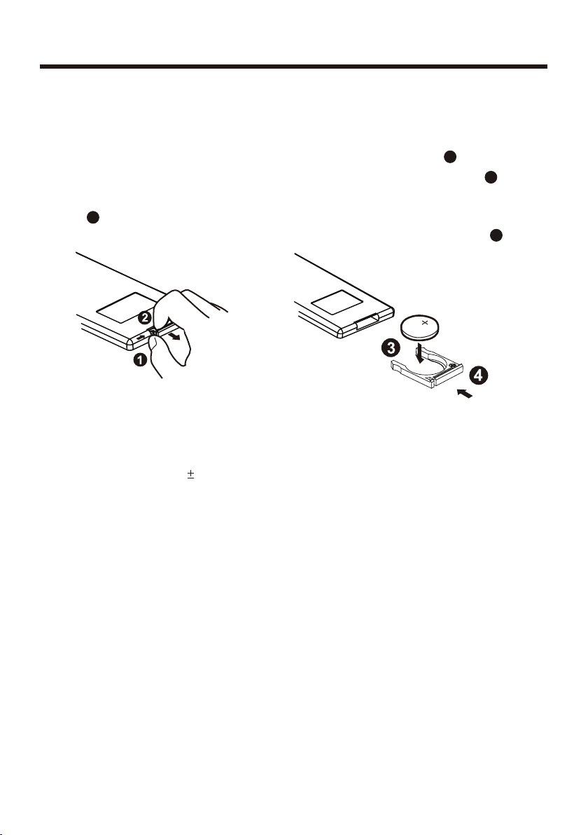
Remote Control
Using the Remote Control
Face the remote control towards the player front face IR mark (remote control signal
receiver).
Operation angle: About 30 degree in each the direction of the front of the IR mark.
Preparing the Remote Control
1.First push to inside as the direction indicated by the arrow (See )And then
Remove the battery holder as the direction indicated by the arrow (See ).
2.Replace the battery Set a new battery property with (+)side up as illustrated
(See ).
3.Insert the battery holder. Push in the holder to the original position(See ).
1
2
3
4
Inserting the Battery
Note :
The lithium cell in the battery compartment of remote control has been secured for
transport with a plastic . Before initial use please remove this plastic so that the
remote control is ready for operation .
 Loading...