


CONTENTS LIST
PAGE CONTENTS
2ACCESSORY INCLUDED
3INSTALLATION
4DETACHABLE CONTROL PANEL
6WIRING DIAGRAM
7CONTROL PANEL FUNCTION
8iPod OPERATION
12BASIC OPERATIONS
13MENU OPERATION
14AUDIO OPERATION
15TUNER OPERATION
16RDS OPERATION
17CD /MP3/WMA OPERATION
20USB OPERATION
21MEMORY CARD OPERATION
22MUSIC FILES COPYING / TRANSFERRING
24MUSIC FILES ERASING
26FILES MANAGER
27BLUETOOTH HAND FREE OPERATION
43REMOTE FUNCTION
44SPECIFICATIONS
45TROUBLE SHOOTING
1
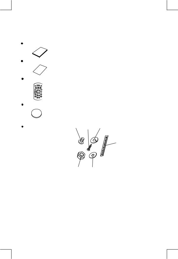
1. ACCESSORY INCLUDED
When first unpacking your new full detachable DVD head unit, please check first that the package contains all of the items below. If something is missing, contact the store where you purchased the player.
Owner’s Manual
O |
|
|
wn |
er’ |
|
ma |
nu |
|
|
s |
|
|
|
al |
Warranty Card
W |
|
|
|
arr |
|
||
Ca |
an |
ty |
|
rd |
|||
|
|
||
Remote control
Lithium Battery
R C
2
0
2
5
+
3V
1. |
Machine Screw (5 x 6mm ) |
1 |
3 |
2 |
2. |
Spring Washer |
|
|
|
|
|
|
||
3. |
Tapping Screw |
|
|
|
4. |
Hex Nut |
|
|
|
5. |
Plain Washer |
|
|
6 |
6. |
Small metal Strip |
|
|
|
4 5
2

2. INSTALLATION
Before finally installing the unit, connect the wiring temporarily and make sure it is all connected up properly and the unit and system work properly.
Use only the parts included with the unit to ensure proper installation. The use of unauthorized parts can cause malfunctions.
Consult with your nearest dealer if installation requires the drilling of holes or other modifications of the vehicle.
Install the unit where it does not get in the driver's way and cannot injure the passenger if there is a sudden stop, like an emergency stop.
If installation angle exceeds 30°from horizontal, the unit might not give its optimum performance. 
Avoid installing the unit where it would be subject to high temperature, such as from direct sunlight, or from hot air, from heater, or where it would be subject to dust dirt or excessive vibration.
Be sure to remove the front panel before installing the unit.
Installation using the screw holes on the side of the unit
Select a position where the screw holes of the bracket and the screw holes of the main unit become aligned (are fitted) and tighten the screws at 2 places on each side.
 Screw
Screw
Screw
 Dashboard or console
3

3. DETACHABLE CONTROL PANEL (D.C.P.)
Removing The Detachable Control Panel (D.C.P)
1 |
2 |
Press the panel release button.
Slighly lift up the panel & pull out the panel side way in order to remove the front panel.
 WARNING
Do not try to remove the panel by pulling directly towards you.
Correct way to remove the panel should be slighly lift up the panel & pull out the panel side way in order to remove the front panel!
Attaching the DCP
1. Attach the panel at the right side first, with point B on the main unit touching point A on the D.C.P. (As shown on the diagram).
2. Then press the left side of D.C.P. onto the main unit until a “click” sound is heard.
A
B
CAUTION
DO NOT insert the D.C.P from the left side. Doing so may damage it.
The D.C.P can easily be damaged by shocks. After removing it, place it in a protective case and be careful not to drop it or subject it to strong shocks.
When the release button is pressed and the D.C.P is unlocked, the car's vibrations may cause it to fall. To prevent damage to the D.C.P, always store it in a protective case after detaching it.
The rear connector that connects the main unit and the D.C.P is an extremely important part. Be careful not to damage it by pressing on it with fingernails, pens, screwdrivers, etc.
Note:
If the D.C.P is dirty, wipe off the dirt with soft, dry cloth only. And use a cotton swab soaked in isopropyl alcohol to clean the socket on the back of the D.C.P.
Socket
4

RESETTING THE UNIT:
After releasing the front panel, use a pencil or any non-metalic object to press & hold the reset button for five seconds to reset the unit.
PRESS DOWN
RESET
5
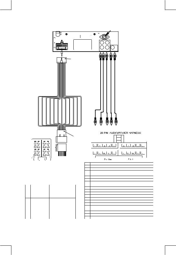
4. WIRING DIAGRAM (20 PIN + ISO PLUG)
FUSE
20-PIN
AUDIO/POWER
HARNESS
(See Figure 1)
PIN(B8) GREEN/BLACK |
PIN(B7) GREEN |
PIN(B6) WHITE/BLACK |
PIN(B5) WHITE |
PIN(B4) GREY/BLACK |
PIN(B3) GREY |
PIN(B2) VIOLET/BLACK |
PIN(B1) VIOLET |
PIN(A8) BLACK |
PIN(A7) RED |
PIN(A5) BLUE |
PIN(A4) YELLOW |
ANT.
L |
L |
R |
R |
REAR |
FRONT SUB-W OUT |
CABLE RCA-TO-RCA Supplied) (Not
CH-R OUT LINE REAR |
CH-L OUT LINE REAR |
CH-R OUT LINE FRONT |
CH-L OUT LINE FRONT |
OUT W-SUB |


 B CONNECTOR
7 |
8 |
7 |
8 |
5 |
6 |
5 |
6 |
3 |
4 |
3 |
4 |
1 |
2 |
1 |
2 |
ISO
CONNECTOR
(See Figure 2)
A CONNECTOR
|
Figure 2 |
|
|
|
|
|
|
ISO CONNECTOR 4PIN+8PIN |
PIN |
WIRE COLOR |
FUNCTION/LABEL |
||
|
FEMALE WITH MALE TERMINAL |
1 |
GREY/BLACK |
RIGHT FRONT SPEAKER (-) |
||
|
|
|
2 |
GREY |
RIGHT FRONT SPEAKER (+) |
|
|
|
|
3 |
VIOLET |
RIGHT REAR SPEAKER (+) |
|
|
|
|
4 |
VIOLET/BLACK |
RIGHT REAR SPEAKER (-) |
|
|
|
|
5 |
|
|
|
|
|
|
6 |
GREEN |
LEFT REAR SPEAKER (+) |
|
|
ISO CONNECTOR WIRING CHART |
7 |
GREEN/BLACK |
LEFT REAR SPEAKER (-) |
||
PIN |
WIRE COLOR |
FUNCTION/LABEL |
8 |
RED |
IGNITION(ACC) |
|
|
|
|
||||
A4 |
YELLOW |
CONSTANT 12 VOLTS |
9 |
|
|
|
A5 |
BLUE |
POWER ANTENNA/REMOTE TURN ON |
10 |
|
LEFT FRONT SPEAKER (+) |
|
A7 |
RED |
IGNITION(ACC) |
11 |
WHITE |
||
|
||||||
A8 |
BLACK |
GROUND |
12 |
WHITE/BLACK |
LEFT FRONT SPEAKER (-) |
|
B1 |
VIOLET |
RIGHT REAR SPEAKER (+) |
13 |
|
|
|
B2 |
VIOLET/BLACK |
RIGHT REAR SPEAKER (-) |
14 |
BLUE |
POWER ANTENNA/REMOTE TURN ON |
|
B3 |
GREY |
RIGHT FRONT SPEAKER (+) |
15 |
YELLOW |
CONSTANT 12 VOLTS |
|
B4 |
GREY/BLACK |
RIGHT FRONT SPEAKER (-) |
16 |
BLACK |
CHASSIS GROUND |
|
B5 |
WHITE |
LEFT FRONT SPEAKER (+) |
17 |
|
|
|
B6 |
WHITE/BLACK |
LEFT FRONT SPEAKER (-) |
18 |
|
|
|
B7 |
GREEN |
LEFT REAR SPEAKER (+) |
19 |
|
|
|
B8 |
GREEN/BLACK |
LEFT REAR SPEAKER (-) |
20 |
|
|
|
6

5. CONTROL PANEL FUNCTION(RDS+BLUETOOTH+iPod)
3 |
10 |
5 |
18 |
2 |
8 |
6 4 9 1 12 13 22 14 19 15 16 17 7 21 20 11
OPERATIONS:
|
SYSTEM |
TUNER |
CD/MP3/WMA |
Bluetooth |
iPod |
|||||||||
KEY |
Short |
|
Long |
Short |
Long |
Short |
|
Long |
Short |
|
Long |
Short |
|
Long |
|
|
|
|
|||||||||||
|
|
|
|
|
||||||||||
|
Press |
|
Press |
Press |
Press |
Press |
|
Press |
Press |
|
Press |
Press |
|
Press |
1 |
Power |
|
|
|
|
|
|
|
|
|
|
|
|
|
|
|
|
|
|
|
|
|
|
|
|
|
|
|
|
2 |
|
|
|
|
|
Eject |
|
|
|
|
|
|
|
|
3 |
|
|
|
|
|
Panel release button |
|
|
|
|
|
|
||
4 |
Audio Menu |
|
|
Enter |
|
|
Phone |
|
|
|
|
|
||
|
|
|
|
Answer |
|
Call |
|
|
|
|||||
5 |
Mode |
|
|
|
|
|
|
|
|
|
|
|
|
|
|
|
|
|
|
|
|
|
|
Transfer |
|
|
|
||
6 |
Encoder Volume |
|
|
|
|
|
|
|
|
|
|
|
||
7 |
|
|
|
Band |
|
File/Folder |
|
File |
Reject Call |
|
|
iPod |
|
|
|
|
|
|
|
|
|
|
|||||||
|
|
|
|
Search |
|
Erase |
End Call |
|
|
Search |
|
|
||
8 |
|
|
Sub-W |
AF |
|
|
|
|
|
|
|
|
|
|
9 |
|
|
Copy |
TA |
|
|
|
|
|
|
|
|
|
|
10 |
|
|
ix-Bass |
PTY |
|
|
|
|
|
|
|
|
|
|
11 |
|
|
|
PS |
AS |
ID3 |
|
|
|
|
|
iPod |
|
|
|
|
|
|
|
|
|
|
information |
|
|
||||
12 |
|
|
|
M1 |
Memory 1 |
Pause |
|
|
|
|
|
Pause |
|
|
|
|
|
/Play |
|
|
|
|
|
/Play |
|
|
|||
13 |
|
|
|
M2 |
Memory 2 |
Intro |
|
Folder |
|
|
|
|
|
|
|
|
|
|
Intro |
|
|
|
|
|
|
||||
14 |
|
|
|
M3 |
Memory 3 |
Repeat |
|
Folder |
|
|
|
Repeat |
|
Album |
|
|
|
|
Repeat |
|
|
|
|
Repeat |
|||||
|
|
|
|
|
|
|
|
|
|
|
|
|
||
15 |
|
|
|
M4 |
Memory 4 |
Random |
|
Fol der |
|
|
|
Shuffle |
|
Album |
|
|
|
|
Random |
|
|
|
|
Shuffle |
|||||
|
|
|
|
|
|
|
|
|
|
|
|
|
||
16 |
|
|
|
M5 |
Memory 5 |
Folder |
|
|
|
|
|
|
|
|
|
|
|
|
|
|
Down |
|
|
|
|
|
|
|
|
17 |
|
|
|
M6 |
Memory 6 |
Folder |
|
|
|
|
|
|
|
|
|
|
|
Up |
|
|
|
|
|
|
|
|
|||
18 |
Display |
|
Menu |
|
|
|
|
|
|
|
|
|
|
|
19 |
|
|
|
|
USB Cover / Socket |
|
|
|
|
|
|
|
|
|
20 |
|
|
|
Seek Up/ Dn |
Tune Up/Dn |
Track/File |
|
Fast Forward |
|
|
|
File Up/Dn |
|
Fast Forward |
|
|
|
|
|
|
|
|
|||||||
|
|
|
|
|
|
Up/Dn |
|
/ Backward |
|
|
|
|
|
/ Backward |
21 |
Mute |
|
|
|
|
|
|
|
|
|
|
|
|
|
22 |
|
|
|
|
|
3.5mm Aux In Jack |
|
|
|
|
|
|
||
7

6. iPod OPERATION
INSTALLING iPod INTO THE BUILT-IN iPod DOCKING
Always follow the below steps to install the iPod into the docking station. Incorrect or improper installation may cause permanent damage to the docking or the iPod unit.
Step 1 Press down the button as indicated |
Step 5 Once the stick is completely |
below to unlock the iPod docking. |
pulled out, user should |
Press down |
see the iPod connector, |
|
and user can |
|
connect the iPod |
|
to the connector |
|
as shown in this |
|
step. |
|
Press toward this |
|
lock switch |
Step 2 Pull out the iPod docking as shown below. Step 6 Push the stick & the connected iPod inwards |
|
|
until it stops. |
Pull out |
|
|
Never pull out this stick unless docking is |
Push inwards |
|
completely release out. |
||
|
||
Step 3 Press on this button on the left side |
Step 7 Press the iPod holder on both sides to |
|
as indicated below to |
hold the iPod firmly in place. |
|
unlock the iPod holder. |
|
Press down this button |
Press towards the iPod unit to hold the |
|
iPod unit firmly in place |
Step 4 Pull out the iPod connector as indicated Step 8 |
Push the iPod docking inwards into the |
below. |
unit’s cabinent until a click sound is heard. |
Pull out this stick |
Push the docking back |
8

REMOVE iPod FROM THE BUILT-IN iPod DOCKING
To take out the iPod from the docking station, user can first detach the front panel, and repeat step 1 to step 8 to take out the iPod & return the iPod docking inside the unit’s cabinent.
Step 1 |
Press the button as indicated below to |
Step 5 |
Once the stick with the |
|
|
unlock the iPod docking. |
connected iPod is completely |
||
|
|
|||
|
|
out, user should push on |
|
|
|
|
the locking buttons |
|
|
|
Press down |
on the both sides |
|
|
|
|
of the iPod |
|
|
|
|
connector to |
|
|
|
|
release the |
|
|
|
|
iPod as |
|
Press toward this |
|
|
indicated in the |
||
|
|
lock switch |
||
|
|
picture, and remove the iPod unit. |
||
Step 2 |
Pull out the iPod docking as shown below. Step 6 |
Once the iPod unit is remove, push the |
||
|
|
|
stick backward into the iPod docking |
|
|
|
station until it stops. |
|
|
Pull out |
|
Never pull out this stick unless docking is |
|
completely release out. |
Push inwards |
|
|
Step 3 Press on this button on the left side |
Step 7 Push on the iPod holders on both sides |
as indicated below to |
until they stop. |
unlock the iPod holder. |
|
Press down this button |
Press towards the iPod unit to hold the |
|
iPod unit firmly in place |
||
|
||
Step 4 Pull out the iPod connected as indicated Step 8 |
Push the iPod docking inwards into the |
|
below by pulling out the stick. |
unit’s cabinent until a click sound is heard. |
|
Push the docking back |
Pull out this stick |
to Cabinent |
|
9
iPod FULL CONTROL / OPERATION
This unit is equipped with iPod Ready function which allow end user to have direct control of the iPod on the front panel control button and display iPod song information on the unit's LCD display. Please read below for more details operation.
iPod Compatibility Chart
This unit is support following iPod version
iPod 1G |
Not Supported |
iPod 2G |
Not Supported |
iPod 3G |
Supported |
iPod Mini |
Supported |
iPod 4G |
Supported |
iPod Photo |
Supported |
iPod Nano |
Supported |
iPod 5G(Video) |
Supported |
iPod Touch |
Supported |
iPhone |
Not Supported |
iPod Classic |
All version |
Audio Video File
This unit is NOT ABLE to playback any VIDEO FILE OR VIDEO ALBUM which contained in the iPod Video.
Turning iPod Power On and Off
The iPod power turns on automatically as soon as it is connected to the 30 Pin Connector and as long as the vehicle's ignition is turned ON. The iPod power can be turned OFF by removing the iPod from the 30 Pin Connector or if the vehicle's ignition is turned OFF. Under this condition the iPod will go into pause mode and goes into sleep mode about 2 minutes later
 While the iPod is connected, the power cannot be turned on or off from the iPod itself.
Tips “ |
|
” to disconnect will be shown in the iPod's display while it is connected to the unit . |
|
OK to disconnect |
|
|
|
|
iPod Battery Charging
While connected to the unit, the iPod will automatically start re-charging as long as the vehicle's ignition key is turn to ACC or ON.
Switch to iPod Mode
When the Head unit is power on and iPod is connected to the 30 pin connector, press the mode button to change to iPod mode and the unit will display  for a while then starts
  the music files contained in the iPod and the playback will automatically start. Press Mode button repeatedly to change to other modes or switch back to iPod mode.
iPod information Display on the Head Unit LCD
This unit can display the Song, Artist, Album name and Elapsed time on the LCD display, these information can be displayed by pressing the AS/PS button repeatedly while a iPod Song file is playing.
Searching a Desire Song
Under iPod playback mode, press BAND to enter into the iPod Searching Mode. Pressing BAND button repeatedly to accesses the different searching methods as below :
1)Playlist
2)Artist
3)Album
4)Song
5)Genre
10

Once selected the desire searching method, within 10 second press the AUDIO button as confirm & access into the searching mode, then turn the rotate encode volume knob to navigate thru the Album or Artist or Song contained in the iPod. Press the AUDIO button to confirm & play the selected song. During the searching mode, press AS/PS as quick move back to the last upper level of Album, Playlist, Genre, etc.
Song Select
Press the File UP (>>) or File DOWN (<<) button for less than one second to skip to the next or previous song. Press and Hold File UP (>>) or File DOWN (<<) button for more than 3 seconds to fast forward or fast reverse of the current song.
Song Repeat / Repeat All play :
Pressing the M3 button for more than 3 seconds during iPod playback mode for “REPEAT ALL”. All songs of the current album will be kept on repeat playing until the “Repeat All” function is disabled. To disable current Album “REPEAT ALL” function, long press M3 button more than 3 seconds
Press the M3 button for less than 3 seconds to “REPEAT PLAY” the current song. And keep on repeat playing the current song until the “REPEAT PLAY” function is disabled. To disable current song “REPEAT PLAY”, press the M3 button less than 3 seconds
Shuffle play: / Shuffle Album
Pressing the M4 button for more than 3 seconds during iPod playback mode to activate the “SHUFFLE ALBUM” function. This function allows RANDOM playback of all the albums contained on the iPod. To disable “SHUFFLE ALBUM” function, long press M4 button for more than 3 seconds.
Press the M4 button for less than 3 seconds during iPod playback mode to activate “SHUFFLE PLAY”. This function allows the playback of all the songs in the iPod in random sequence. To disable “SHUFFLE PLAY”, short press M4 button again for less than 3 seconds.
11

7. BASIC OPERATIONS
3) PANEL RELEASE BUTTON (REL)
Press this button to remove the control panel.
1) POWER ON/OFF BUTTON ( )
Press POWER button or any other button on the front of the radio to turn the unit on. Press POWER button again to turn the unit off.
21)MUTE BUTTON (MUTE)
Press the mute button momentarily to mute the audio volume, and "Mute" will flash in the display. Press the mute button again to restore volume to the previous setting.
8)SUBWOOFER (SUB-W)
Pressing the Subwoofer button to activate the Subwoofer function On, and “Subwoofer” will appear on the LCD display for 3 seconds. press the Subwoofer button again to turn off the Subwoofer function.
10) iX-BASS BUTTON (iX-Bass )
Long press the iX-Bass button to turn on the iX-Bass function, and “iX-Bass” will appear in the LCD display for 3 seconds. Press the iX-Bass button again to turn off the iX-Bass function.
5) MODE BUTTON (MODE)
Press MODE button to select a different mode of operation as indicated on the display panel. Available modes include Tuner, USB Host, SD/MMC , iPod and Aux - In .
AUX INPUT
Connect the external signal to AUX in jack located at the front of the panel , then press Mode button to select Aux mode. Press Mode Button again to cancel Aux Mode and return to previous mode.
AUX IN |
FRONT CABINET |
|
|
|
LEFT TRACK |
|
RIGHT TRACK |
|
GROUND |
|
AUX IN |
6)ENCODER VOLUME BUTTON
To increase the volume, rotate the volume control clockwise.To decrease the volume, rotate the volume control counter clockwise.When volume is adjusted, the volume level will be shown on the display panel as a number ranging from 0 (lowest) to 46 (highest).
12

8. MENU OPERATION
18) MENU FUNCTION LIST (MENU) |
|
Press DISPLAY/ MENU for more than 3 seconds to access the menu. |
will |
appear in the display momentarily. Navigate the menu by pressing DISPLAY/ MENU momentarily to move forward to the next option. The menu can also be navigated by using the Tuning Up or Tuning Down Button to move to the next or previous option. Once the desired option appears in the display, adjust that option by rotating the volume control within 5 seconds. The following options are adjusted through this menu feature.
Pairing
This feature is used to pairing the unit's Bluetooth system to your mobile phone or other Bluetooth device. Under the MENU “Pairing” mode then press Audio button to start activating the Pairing.
Tips Please refer to BLUETOOTH HAND FREE operation regarding the details operation of “PAIRING”.
Re-connection/Dis-connection
This feature is allows to Re-connect or Dis-connect to the paired mobile phone or Bluetooth device by manually. Under the Menu- “RE-CONN”mode, Rotate the encoder to navigate thru “RE-CONN” (re-connection) and “DIS-CONN”(Dis-connection). After selected the mode for connection then press Audio button to start activating the connection mode.
Auto Answer (A ANSWER)
The unit is default of “off' mode. If “On” is selected.. The unit is automatically answer any incoming call without pressing PHONE button if ON is selected..
Contrast
The contrast level of the display is set at "CONTRAST 05" by default. Rotate the volume control To adjust the contrast level from 00 to 10.
Clock Format
This option allows selection of a 12 hour or 24 hour clock format. "CLK FORMAT 12H" is the Default setting. Rotate the volume control to change to the 24 hour clock format.
Time Set
The time on the clock will be set to 12:00 as the default. Program the current time by rotating the volume control clockwise to adjust the minutes and counterclockwise to adjust the hours.
Local / Distance Select
This feature is used to designate the strength of the signals at which the radio will stop during automatic tuning. "Distance" is the default, allowing the radio to stop at a broader range of signals. To set the unit to select only strong local stations during automatic tuning, rotate the volume control until "Local" appears in the display.
Beep Tone
The beep tone feature allows the selection of an audible beep tone to be heard each time a button is pressed on the face of the radio. "BEEP TONE On" is the default display. Rotate the volume control to select the "BEEP TONE Off" option.
13

9. AUDIO OPERATION
Audio Menu
Pressing “AUDIO” button to access the Audio Menu. User can navigate thru the Audio Menu items by pressing the / “AUDIO” button repeatedly, or by pressing the Tuning Up or Tuning Down Button. Once the desired menu item appears on the display, adjust that option by using the Volume Up or Down button within 5 seconds. The following menu items can be adjusted as described above. The unit will automatically exit the Audio Menu after five seconds of inactivity.
VOLUME (Volume Level)
User has 5 seconds to use the Volume button to adjust the desire volume level, the volume level will be shown on the LCD display ranging from 00 (lowest) to 46 (highest).
BASS (Bass Level)
User has 5 seconds to use the Volume Up or Down button to adjust the desired Bass level range from -6 to +6.
TREBLE (Treble Level)
User has 5 seconds to use the Volume Up or Down button to adjust the desired Treble level range from -6 to +6.
BALANCE
User has 5 seconds to use the Volume Up or Down button to adjust the Balance between the right and left speakers from R12 (full right) to L12 (full left). “C00” represents an equal balance between the right and left speakers.
FADER
User has 5 seconds to use Volume Up or Down button to adjust the Fader between the front and rear speakers from R12 (full rear) to F12 (full front). “C00” represents an equal balance between the front and rear speakers.
14
 Loading...