


Thank you for choosing Boss Audio Systems! This unit will bring you years of enjoyment.
CONTENTS |
|
Safety Precautions................................................................. |
2-3 |
Installation............................................................................. |
4-6 |
Wiring Connections................................................................... |
7 |
Basic Operation........................................................................ |
8 |
RadioOperation......................................................................... |
9 |
DVD/VCD/CD/MP3/WMA Operation.................................. |
10-14 |
Other Operation....................................................................... |
15 |
Maintenance........................................................................... |
16 |
IR Remote Control................................................................... |
17 |
Troubleshooting Guide........................................................... |
18 |

SAFETY PRECAUTIONS
 Important Warnings to Take Note of BEFORE Starting the Installation
 Damage Caused By Incorrect Installation or Usage is NOT Covered By Warranty.
PLEASE Take the Time to Read the Installation Notes Carefully.
 Please make all necessary connections and terminate any unused wires so they do not short. If you feel uncomfortable preforming the install consult a professional installer.
 To ensure safety while driving and to comply with laws, drivers should not watch video or operate the video device while driving
 To avoid any possible damage to your vehicles electrical system, be sure to disconnect the battery cable before beginning installation.
 The unit is intended for vehicles with a 12-volt battery and negative grounding.
 Before installing the unit in a recreational vehicle, truck, or bus, check that the battery voltage is 12 volts.
 Remove the two transport screws from the top of the unit before installation.
 Be sure to connect the negative (-) speaker leads to the negative (-) speaker terminal. Never connect the negative (-) speaker leads to chassis ground.
 This unit is only designed for use with 4 speakers. Do not combine outputs for use with 2 speakers. Do not ground negative speaker leads to the chassis ground.
 Speakers connected to this unit must be 4 to 8 ohms. Connecting speakers with output and/or impedance values other than those noted there will result in damage to the head unit and the speakers.
 Check the condition off your speakers carefully - connecting the unit to old of degraded speakers may result in a fault which will damage the audio IC and invalidate the warranty.
 If this unit is installed in a vehicle that does not have an ACC (accessory) position on the ignition switch, the red lead of the unit should be connected to a terminal coupled with ignition switch ON/OFF operations. If this is not done, the vehicle battery may be drained when you are away from the vehicle for several hours.
2

SAFETY PRECAUTIONS
 Secure the wiring with zip ties or electrical tape. . To protect the wiring, wrap adhesive tape around them where they lie against metal parts. To avoid short-circuiting, cover all disconnected lead with insulating tape. There is a possibility of short-circuiting if the leads are not insulated.
 Route and secure all wiring so it cannot touch any moving parts, such as the gear lever and handbrake. Do not route wiring in places that get hot, such as near the heater outlet. If the insulation of the wiring melts or gets torn, there is a danger of the wiring short circuiting to the vehicle’s body.
 Don’t pass the yellow lead through a hole into the engine compartment to connect to the battery. This will damage the lead’s insulation and cause a very dangerous short.
 Do not shorten any leads, if you do, the protection circuit may fail to work when it should.
 Never feed power to other equipment by cutting the insulation of the power supply lead of the unit and tapping into the lead. The current capacity of the lead will be exceeded, causing overheating.
 Since a unique audio I/C circuit is employed, never wire so the speaker leads are directly grounded or the left and right - speaker leads are common.
 When this product’s source is switched ON, a control signal is turned on through the Blue/White lead. Connect to an external power amp’s system remote control or the car’s Auto-antenna relay control terminal (max. 500mA 12V DC).
 Do not block any vents or heater panels, Blocking them will cause heat to build up and may result in fire.
 When replacing the fuse(s) the replacement must be of the same amperage as shown on the fuse holder. Never replace a fuse with another of a different value. If the fuse blows again please contact your instsallation company.
 Double check that all wiring and connections are correct before re-connecting the battery and turning on the unit.
After completing the installation and before operating the unit, reconnect the battery, then press the (RES) button with a pointed object, such as a ball-point pen to set to unit to it’s initial status. After pushing the button, wait a few seconds for the red light to flash.
3

INSTALLATION
Tools for Installation
2 removal wrenches are supplied for taking out the old unit and place with this brand name car radio. The following tools and supplies may also be needed for the installation:
Tools for Installation: Philips Screw-drivers /Machine Screws /Wire Stripper /Wire Cutter /Hammer /Pencil /Electrical Tape /Electric Drill
Supplies for Installation: Machine Screws /Crimp Connectors /14 Gauge Wire for Power Connections /14-16 Gauge Speaker Wires
The above are not supplied.
Before you install
We strongly recommend that this unit should be professionally installed by a VAT registered installer (this is a requirement to validate the warranty). IMPORTANT: Remove the two transport screws from the top fo the unit before installing.
Remove the Old Unit from the Dashboard
1. Remove the outer trim frame.
2.Insert the keys supplied with the old unit into both sides of the unit as shown in figure below until they click. Pull to remove the old unit from the dashboard.
DIN Front Mount |
DO NOT DISCONNECT WIRES |
|
AT THIS TIME! |
Mark Polarity of the Speaker Wires
Marking the polarity of the speaker wirers will make it easier to connect the existing speakers to your car radio. Consult wiring diagram of existing head unit before disconnecting any wires. If you are not positive of the polarity of the existing wires from the speakers to the head unit, install new wires.
1.While the old unit is playing, disconnect the wires from one speaker.
2.Take a length of masking tape and fold it around the wire so it forms a flag.
3.On the masking tape mark the polarity of the speaker wires (+&-), as well as left or right, and front or rear.
4.Double check that you marked the first speaker correctly by checking that the speaker wires are the same at the head unit.
5.Repeat this procedure for all of the speakers.
6.Mark the power, ground, and any other wires also.
4
INSTALLATION
WARNING!
Disconnect negative battery terminal from battery before starting installation.
NOTE: Mark the polarity of the existing speaker wires before disconnecting battery.
NOTE: Remove the two transport screws from the top of the unit before installing.
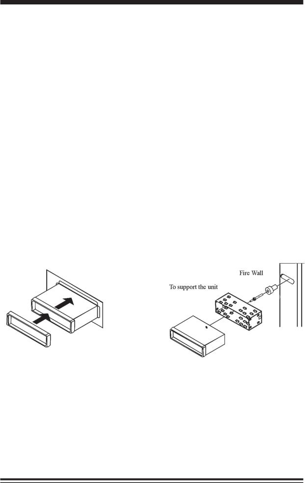
DIN Front Mount
1. After removing the old radio and mounting sleeve, insert supplied mounting sleeve into opening.
2. Bend the tabs on the mounting sleeve to keep the mounting sleeve firmly in place.
3. Attach wires from the unit to existing wires. See wiring connections diagram. Insert radio into dashboard. Then apply the trim frame to outside of radio.
4. Support radio using rear mounting bolt and steel bar. (not included)
5
INSTALLATION
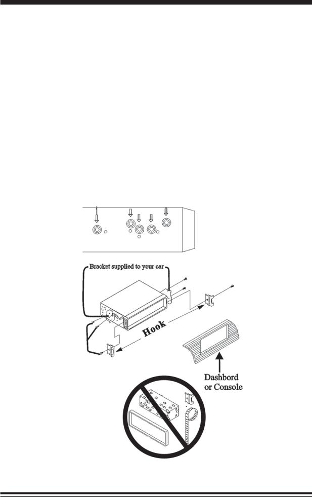
DIN Rear Mount
NOTE: Outer trim frame, hook, and mounting sleeve are not used for this installation
This is only intended as a general guide; contact the vehicle’s manufacturer for specific instructions.
This menthod of installation uses the screw holes at the sides of the unit and the holes of the existing vehicle mounting bracket.
1.Remove the hooks on both sides.
2.Aligh the screw holes of the mounting bracket supplied with the car and the screw holes of the main unit. Tighten the 2 screws on each side of the unit. Then fasten the brackets to the car.
3.Attach wires of the unit to existing speaker wires. See wiring diagram.
6
 Loading...