


VIP XD
Network Video Server
en Installation and Operating Manual

VIP XD |
Table of Contents | en |
3 |
|
|
|
Table of Contents
1 |
Preface |
5 |
1.1 |
About this Manual |
5 |
1.2 |
Conventions in this Manual |
5 |
1.3 |
Intended Use |
5 |
1.4 |
EU Directives |
6 |
1.5 |
Rating Plate |
6 |
2 |
Safety Information |
7 |
2.1 |
Electric Shock Hazard |
7 |
2.2 |
Installation and Operation |
7 |
2.3 |
Maintenance and Repair |
7 |
3 |
Product Description |
9 |
3.1 |
Scope of Delivery |
9 |
3.2 |
System Requirements |
10 |
3.3 |
Overview of Functions |
11 |
3.4 |
Connections on the Front Panel |
13 |
3.5 |
Connections on the Rear Panel |
14 |
4 |
Installation |
15 |
4.1 |
Preparations |
15 |
4.2 |
Connections |
16 |
4.3 |
Power On/Power Off |
19 |
4.4 |
Setup Using the Configuration Manager |
19 |
5 |
Configuration Using a Web Browser |
21 |
5.1 |
Connecting |
21 |
5.2 |
Configuration Menu |
24 |
5.3 |
Identification |
25 |
5.4 |
Password |
25 |
5.5 |
Date/Time |
26 |
5.6 |
Appearance |
28 |
5.7 |
Decoder Profile |
29 |
5.8 |
VGA |
30 |
5.9 |
Monitor Display |
33 |
5.10 |
Audio (Audio Version Only) |
33 |
5.11 |
Alarm Connections |
34 |
5.12 |
Audio Alarm (Audio Version Only) |
37 |
5.13 |
Alarm E-Mail |
38 |
5.14 |
Alarm Task Editor |
40 |
5.15 |
Alarm Inputs |
41 |
5.16 |
Relay |
41 |
5.17 |
COM1 |
43 |
5.18 |
Network |
44 |
5.19 |
Advanced |
47 |
Bosch Security Systems |
Installation and Operating Manual |
DOC | V4.0 | 2009.06 |
4 en | Table of Contents VIP XD
5.20 |
Encryption |
48 |
5.21 |
Maintenance |
49 |
5.22 |
Licenses |
51 |
5.23 |
System Overview |
51 |
5.24 |
Function Test |
52 |
|
|
|
6 |
Operation |
53 |
6.1 |
Connecting |
53 |
6.2 |
The CONNECTIONS Page |
56 |
6.3 |
Connections Between the Sender and Receiver |
57 |
6.4 |
Hardware Connections Between Video Servers |
59 |
6.5 |
Operation with Management Software |
60 |
|
|
|
7 |
Maintenance and Upgrades |
61 |
7.1 |
Testing the Network Connection |
61 |
7.2 |
Unit Reset |
61 |
7.3 |
Repairs |
62 |
7.4 |
Transfer and Disposal |
62 |
|
|
|
8 |
Appendix |
63 |
8.1 |
Troubleshooting |
63 |
8.2 |
LEDs |
65 |
8.3 |
Processor Load |
65 |
8.4 |
Network Connection |
65 |
8.5 |
Serial Interface |
66 |
8.6 |
Terminal Block |
66 |
8.7 |
Communication with Terminal Program |
67 |
8.8 |
Copyrights |
69 |
|
|
|
9 |
Specifications |
71 |
9.1 |
Unit |
71 |
9.2 |
Protocols/Standards |
72 |
|
|
|
10 |
Glossary |
73 |
|
|
|
11 |
Index |
77 |
DOC | V4.0 | 2009.06 |
Installation and Operating Manual |
Bosch Security Systems |
VIP XD Preface | en 5
1 |
Preface |
1.1 |
About this Manual |
|
This manual is intended for persons responsible for the installation and operation of the |
|
VIP XD. International, national and any regional electrical engineering regulations must be |
|
followed at all times. Relevant knowledge of network technology is required. The manual |
|
describes the installation and operation of the unit. |
1.2 |
Conventions in this Manual |
|
In this manual, the following symbols and notations are used to draw attention to special |
|
situations: |
CAUTION!
!This symbol indicates that failure to follow the safety instructions described may endanger persons and cause damage to the unit or other equipment.
It is associated with immediate, direct hazards.
NOTICE!
This symbol refers to features and indicates tips and information for easier, more convenient use of the unit.
1.3 Intended Use
The VIP XD network video server receives video and control signals over data networks (Ethernet LAN, Internet). Audio signals can also be transmitted with the audio version of the unit. The units are designed for use in CCTV systems. Various functions can be triggered automatically by incorporating external alarm sensors. Other applications are not permitted. In the event of questions concerning the use of the unit which are not answered in this manual, please contact your sales partner or:
Bosch Security Systems
Robert-Koch-Straße 100 85521 Ottobrunn Germany www.boschsecurity.com
Bosch Security Systems |
Installation and Operating Manual |
DOC | V4.0 | 2009.06 |

6 en | Preface VIP XD
1.4 |
EU Directives |
|
The VIP XD network video server complies with the requirements of EU Directives 89/336 |
|
(Electromagnetic Compatibility) and 73/23, amended by 93/68 (Low Voltage Directive). |
1.5 |
Rating Plate |
|
For exact identification, the model name and serial number are inscribed on the bottom of the |
|
housing. Please make a note of this information before installation, if necessary, so as to have |
|
it to hand in case of questions or when ordering spare parts. |
DOC | V4.0 | 2009.06 |
Installation and Operating Manual |
Bosch Security Systems |

XIP XD Safety Information | en 7
2 |
Safety Information |
2.1 |
Electric Shock Hazard |
|
– Never attempt to connect the unit to any power network other than the type for which it |
|
is intended. |
|
– Use only the power supply unit provided. |
|
– Never open the housing. |
|
– Never open the housing of the power supply unit. |
|
– If a fault occurs, disconnect the power supply unit from the power supply and from all |
|
other units. |
|
– Install the power supply and the unit only in a dry, weather-protected location. |
|
– If safe operation of the unit cannot be ensured, remove it from service and secure it to |
|
prevent unauthorized operation. In such cases, have the unit checked by Bosch Security |
|
Systems. |
|
Safe operation is no longer possible in the following cases: |
|
– if there is visible damage to the unit or power cables, |
|
– if the unit no longer operates correctly, |
|
– if the unit has been exposed to rain or moisture, |
|
– if foreign bodies have penetrated the unit, |
|
– after long storage under adverse conditions, or |
|
– after exposure to extreme stress in transit. |
2.2 |
Installation and Operation |
|
– The relevant electrical engineering regulations and guidelines must be complied with at |
|
all times during installation. |
|
– Relevant knowledge of network technology is required to install the unit. |
|
– Before installing or operating the unit, make sure you have read and understood the |
|
documentation for the other equipment connected to it, such as monitors. The |
|
documentation contains important safety instructions and information about permitted |
|
uses. |
|
– Perform only the installation and operation steps described in this manual. Any other |
|
actions may lead to personal injury, damage to property or damage to the equipment. |
2.3 |
Maintenance and Repair |
|
– Never open the housing of the VIP XD. The unit does not contain any user-serviceable |
|
parts. |
|
– Never open the housing of the power supply unit. The power supply unit does not contain |
any user-serviceable parts.
– Ensure that all maintenance or repair work is carried out only by qualified personnel (electrical engineers or network technology specialists).
Bosch Security Systems |
Installation and Operating Manual |
DOC | V4.0 | 2009.06 |

8 |
en | Safety Information |
XIP XD |
|
|
|
DOC | V4.0 | 2009.06 |
Installation and Operating Manual |
Bosch Security Systems |
VIP XD Product Description | en 9
3 |
Product Description |
||
3.1 |
Scope of Delivery |
||
|
– VIP XD network video server (basic version or audio version) |
||
|
– Power supply unit with four primary adapters |
||
|
– |
Configuration cable |
|
|
– |
Quick Installation Guide |
|
|
– Product CD with the following content: |
||
|
|
– |
Quick Installation Guide |
|
|
– |
Manual |
|
|
– |
System Requirements document |
|
|
– Further documentation on Bosch Security Systems products |
|
|
|
– |
Configuration Manager |
|
|
– |
MPEG ActiveX control |
|
|
– Player and Archive Player |
|
|
|
– |
DirectX control |
|
|
– |
Microsoft Internet Explorer |
|
|
– |
Sun JVM |
|
|
– |
Adobe Acrobat Reader |
NOTICE!
Check that the delivery is complete and in perfect condition. Arrange for the unit to be checked by Bosch Security Systems if you find any damage.
Bosch Security Systems |
Installation and Operating Manual |
DOC | V4.0 | 2009.06 |
10 en | Product Description VIP XD
3.2 System Requirements
General Requirements
–Computer with Windows XP or Windows Vista operating system
–Network access (Intranet or Internet)
–Screen resolution 1,024 × 768 pixels
–16or 32-bit color depth
–Installed Sun JVM
NOTICE!
Also note the information in the System Requirements document on the product CD supplied. If necessary, you can install the required programs and controls from the product CD supplied (see Section 3.1 Scope of Delivery, page 9).
The Web browser must be configured to enable Cookies to be set from the IP address of the unit.
In Windows Vista, deactivate protected mode on the Security tab under Internet Options. You can find notes on using Microsoft Internet Explorer in the online Help in Internet Explorer.
Additional Configuration Requirements
–Microsoft Internet Explorer (version 6.0 or higher) or
–Installed Configuration Manager program (version 2.0 or higher)
Additional Operational Requirements
–Microsoft Internet Explorer (version 6.0 or higher) or
–Management software, for example VIDOS (version 3.11 or higher) or Bosch Video Management System (version 2.02 or higher)
DOC | V4.0 | 2009.06 |
Installation and Operating Manual |
Bosch Security Systems |
VIP XD Product Description | en 11
3.3 Overview of Functions
Network Video Receiver with Quad View
The VIP XD is an ultra-compact network video receiver for simultaneous reception of up to four video streams. It is primarily designed for decoding video data after transfer over an IP network and for transmitting control data. When connected to a monitor and used in conjunction with compatible MPEG-4 video servers, the VIP XD is ideally suited for making existing analog CCTV systems IP-compatible.
The VIP XD is small enough to be easily integrated into small housings as well. The use of existing networks means that integration with CCTV systems or local networks can be achieved quickly and easily.
Two units, for example a VIP X1600 as a sender and a VIP XD as a receiver, can create a standalone system for data transfer without a PC. Video images from a single sender can be received simultaneously on multiple receivers. A VIP XD receiver can simultaneously receive up to four video streams from one or more compatible senders.
The audio version of the VIP XD also allows the transmission of audio signals from and to compatible units.
Sender
Compatible hardware encoders can be used as senders, for example VIP X1, VIP X1600 or VideoJet X40. Computers with installed VIDOS software are suitable for convenient connection of the required senders to the respective receivers.
Multicast
In suitably configured networks, the multicast function enables simultaneous real-time video transmission to multiple receivers. The UDP and IGMP V2 protocols must be implemented on the network for this function.
Encryption
The VIP XD offers a variety of options for protection against unauthorized reading. Web browser connections can be protected using HTTPS. You can protect the control channels via the SSL encryption protocol. With an additional license, the user data itself can be encrypted.
Configuration
The VIP XD can be configured with a Web browser on the local network (Intranet) or via the Internet. Alternatively, you can perform the configuration using the Configuration Manager program, which is contained on the product CD included in the scope of delivery.
In the same way, firmware updates and fast loading of device configurations are possible.
Bosch Security Systems |
Installation and Operating Manual |
DOC | V4.0 | 2009.06 |

12 en | Product Description |
VIP XD |
|
|
Summary
The VIP XD provides the following main functions:
–Video and data reception over IP data networks
–Quad view function with simultaneous decoding of four video streams
–BNC composite video output (PAL/NTSC) for connecting an analog monitor and Sub-D video interface (VGA/SVGA) for connecting a computer monitor
–Video decoding using MPEG-4, MPEG-2 and H.264
–Integrated Ethernet port (10/100 Base-T)
–Transparent, bidirectional data channel via RS-232/RS-422/RS-485 serial interface
–Configuration and remote control of all internal functions via TCP/IP, also secured via HTTPS
–Password protection to prevent unauthorized connection or configuration changes
–Four alarm inputs for external sensors (such as door contacts)
–Relay output for switching external units (such as lamps or sirens)
–Event-controlled automatic connection
–Convenient maintenance via uploads
–Flexible encryption of control and data channels
–Authentication according to international standard 802.1x
The audio version also offers:
–Transmission and receipt of audio signals
–Bidirectional audio (mono) for line or microphone/speaker links
–Audio encoding to international standard G.711
DOC | V4.0 | 2009.06 |
Installation and Operating Manual |
Bosch Security Systems |
VIP XD Product Description | en 13
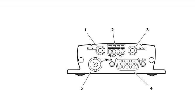
3.4 Connections on the Front Panel
1Line In audio line input (audio version only)
3.5 mm / 1/8 in. stereo socket for connecting an audio line input signal
2Terminal connector (audio version only)
for microphone and loudspeaker connections
3Line Out audio line output (audio versions only)
3.5 mm / 1/8 in. stereo socket for connecting an audio line output signal
4VGA video output
Sub-D socket for connecting a computer monitor
5Video Out video output
BNC socket for connecting a video monitor
Bosch Security Systems |
Installation and Operating Manual |
DOC | V4.0 | 2009.06 |
14 en | Product Description VIP XD
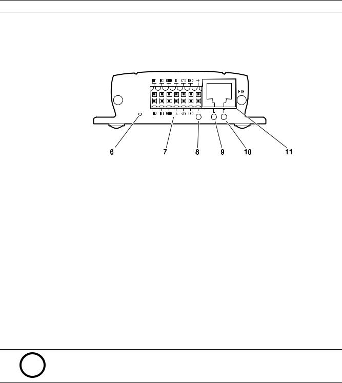
3.5 Connections on the Rear Panel
6Factory reset button
to restore factory default settings
7Terminal block
for alarm inputs, relay output, serial interface and power supply
8Operating status LED
lights up green when ready for operation
9L LED
lights up green when the unit is connected to the network
10T LED
flashes orange when data is being transmitted over the network
11ETH RJ45 socket
for connecting to an Ethernet LAN (local network), 10/100 MBit Base-T
NOTICE!
For more information about the LEDs, see Section 8.2 LEDs, page 65.
For terminal block assignment, see Section 8.6 Terminal Block, page 66.
DOC | V4.0 | 2009.06 |
Installation and Operating Manual |
Bosch Security Systems |
VIP XD |
Installation | en 15 |
|
|
4 Installation
4.1 Preparations
Thanks to its ultra-compact dimensions, the VIP XD is particularly well suited to installation in cabinets or consoles where space is at a premium.
CAUTION!
The unit is intended for use indoors or in housings.
Select a suitable location for installation that guarantees to meet the environmental
!conditions. The ambient temperature must be between 0 and +50 °C (+32 and +122 °F). The relative humidity must not exceed 95%.
The VIP XD generates heat during operation, so you should ensure that there is adequate ventilation and enough clearance between the unit and heat-sensitive objects or equipment.
Please ensure the following installation conditions:
–Do not install the unit close to heaters or other heat sources. Avoid locations exposed to direct sunlight.
–Allow sufficient space for running cables.
–Ensure that the unit has adequate ventilation.
–When making connections, use only the cables supplied or use appropriate cables immune to electromagnetic interference.
–Position and run all cables so that they are protected from damage, and provide adequate cable strain relief where needed.
–Avoid impacts, blows and severe vibrations as these can irreparably damage the unit.
Bosch Security Systems |
Installation and Operating Manual |
DOC | V4.0 | 2009.06 |
16 en | Installation |
VIP XD |
|
|
4.2 Connections
Monitors
As required, you can connect an analog video monitor (PAL/NTSC) or a VGA-compatible computer monitor.
XConnect an analog video monitor to the BNC Video Out socket using a video cable (75 Ohm, BNC plug) or
Xconnect a VGA-compatible computer monitor to the VGA sub-D socket using a video cable (VGA,
15-pin sub-D plug).
Audio Connections (Audio Version Only)
The audio version of the VIP XD has two audio ports for audio line signals as well as a microphone input and a loudspeaker output.
The audio signals are transmitted two-way and in sync with the video signals. As a result, you can connect a speaker or door intercom system at the destination point, for example.
NOTICE!
If possible you should use the line ports of the intercom for transmitting audio signals on the intercom systems. The following specifications should be complied with in all cases.
Line In: |
Impedance 9 kOhm typ., 5.5 Vp-p max. input voltage |
Line Out: |
Impedance 16 Ohm min., 3 Vp-p max. output voltage |
MIC (microphone): |
Impedance 2 kOhm typ., 2.8 Vp-p max. input voltage, |
|
–20 dB in, power supply 2.3 V typ. |
|
|
SPK (loudspeaker): |
Impedance 4 Ohm min., 6 Vp-p max. output voltage, |
|
power output RMS 1 W |
|
|
The stereo plugs must be connected as follows:
Contact |
Function |
|
|
Tip |
Channel 1 |
|
|
Middle ring |
– |
|
|
Lower ring |
Ground |
|
|
1.Connect an audio source with line level to the Line In socket of the VIP XD with a 3.5 mm stereo plug.
2.Connect a unit with line-in connection to the Line Out socket of the VIP XD with a 3.5 mm stereo plug.
If you wish to connect a microphone and a loudspeaker directly:
1.Connect the microphone cords to the MIC and GND connections on the push-in terminal.
2.Connect the loudspeaker cords to the SPK connections on the push-in terminal.
DOC | V4.0 | 2009.06 |
Installation and Operating Manual |
Bosch Security Systems |
VIP XD |
Installation | en 17 |
|
|
Network
You can connect the VIP XD to a 10/100 Base-T network using a standard UTP category 5 cable with RJ45 plugs.
XConnect the VIP XD to the network via the ETH socket.
Data Interface
The bi-directional data interface is used to control units connected to the VIP XD, for example a control panel for dome cameras with motorized lens. The connection supports the RS-232, RS-422 and RS-485 transmission standards.
The VIP XD offers the serial interface via the orange terminal block (see Section 8.6 Terminal Block, page 66).
The range of controllable equipment is expanding constantly. The manufacturers of the relevant equipment provide specific information on installation and control.
CAUTION!
Please take note of the appropriate documentation when installing and operating the unit to
!be controlled.
The documentation contains important safety instructions and information about permitted uses.
NOTICE!
A video connection is necessary to transmit transparent data.
Alarm Inputs
The VIP XD has four alarm inputs on the orange terminal block (see Section 8.6 Terminal Block, page 66). The alarm inputs are used to connect to external alarm devices such as door contacts or sensors. With the appropriate configuration, an alarm sensor can automatically connect the VIP XD to a particular sender, for example.
A zero potential closing contact or switch can be used as the actuator.
NOTICE!
If possible, use a bounce-free contact system as the actuator.
X Connect the lines to the appropriate terminals on the orange terminal block (IN1 to IN4) and check that the connection is secure.
Bosch Security Systems |
Installation and Operating Manual |
DOC | V4.0 | 2009.06 |
18 en | Installation |
VIP XD |
|
|
Relay Output
The VIP XD has a relay output for switching external units such as lamps or sirens. This relay output can be activated manually during a connection session with the VIP XD. The output can also be configured to automatically activate sirens or other alarm units in response to an alarm signal. The relay output is also located on the orange terminal block (see
Section 8.6 Terminal Block, page 66).
CAUTION!
!The maximum rating of the relay contact is 30 V and 2 A (SELV).
X Connect the lines to the appropriate terminals of the orange terminal block (R) and check that the connection is secure.
DOC | V4.0 | 2009.06 |
Installation and Operating Manual |
Bosch Security Systems |
VIP XD Installation | en 19
4.3 Power On/Power Off
Power Supply
The VIP XD comes with a plug-in power supply unit (PSU) with four primary adapters and a terminal block. The VIP XD does not have a power switch. The VIP XD is ready for operation as soon as it is connected to the power supply.
CAUTION!
The VIP XD may only be operated using the supplied PSU with the correct primary adapter for
!your power outlet.
Where necessary, use suitable equipment to ensure that the power supply is free from interference such as voltage surges, spikes or voltage drops.
Do not connect the VIP XD to the power supply until all other connections have been made.
1.Plug the terminal block with the PSU cable connected to it into the orange socket on the VIP XD.
2.Ensure that the correct primary adapter is attached to the power supply unit and that a suitable power outlet is available.
3.Plug the power supply unit into the grounded power outlet. The unit is ready for operation as soon as the operating status LED stops flashing red during start-up and lights up green.
|
Provided the network connection has been correctly made, the green L LED also lights up. |
|
The flashing orange T LED indicates data traffic on the network. |
4.4 |
Setup Using the Configuration Manager |
|
The Configuration Manager program can be found on the product CD contained in the scope |
|
of delivery. This program allows you to implement and set up new video servers in the |
|
network quickly and conveniently. |
NOTICE!
Using the Configuration Manager to set all parameters in the VIP XD is an alternative to configuration by means of a Web browser, as described in chapter 5 of this manual.
Installing the Program
1.Insert the CD into the computer's CD-ROM drive.
2.If the CD does not start automatically, open the Configuration Manager directory using Windows Explorer and double-click Setup.exe.
3.Follow the on-screen instructions.
Bosch Security Systems |
Installation and Operating Manual |
DOC | V4.0 | 2009.06 |

20 en | Installation |
VIP XD |
|
|
Configuring the VIP XD
You can start the Configuration Manager immediately after installation.
1.Double-click the icon on the desktop or start the program via the Start menu. After the program has started, the network is immediately searched for compatible video servers.
2.You can start the configuration if a VIP XD is shown in the list in the left section of the window. To do this, right-click the entry for the unit.
3.Click Unit network settings... in the popup menu.
4.In the Unit IP address field, enter a valid IP address for your network (for example 192.168.0.32) and click OK. The unit reboots and the IP address is valid.
5.If required, enter an appropriate subnet mask for the IP address, and additional network data.
NOTICE!
You must reboot to activate the new IP address, a new subnet mask or a gateway IP address.
Reboot
You can trigger the reboot directly with the assistance of the Configuration Manager.
XRight-click the entry for the unit in the list in the left section of the window and select the Reset command from the context menu.
Additional Parameters
You can check and set additional parameters with the assistance of the Configuration Manager. You can find detailed information on this in the documentation for this program.
DOC | V4.0 | 2009.06 |
Installation and Operating Manual |
Bosch Security Systems |
VIP XD Configuration Using a Web Browser | en 21
5 Configuration Using a Web Browser
5.1 Connecting
The integrated HTTP server in the VIP XD provides you with the option to configure the unit over the network with a Web browser. This option is an alternative to configuration using the Configuration Manager program and is considerably richer in function and more convenient than configuration using the terminal program.
System Requirements
–Computer with Windows XP or Windows Vista operating system
–Network access (Intranet or Internet)
–Microsoft Internet Explorer (version 6.0 or higher)
–Screen resolution 1,024 × 768 pixels
–16or 32-bit color depth
–Installed Sun JVM
NOTICE!
Also note the information in the System Requirements document on the product CD supplied. If necessary, you can install the required programs and controls from the product CD supplied (see Section 3.1 Scope of Delivery, page 9).
The Web browser must be configured to enable Cookies to be set from the IP address of the unit.
In Windows Vista, deactivate protected mode on the Security tab under Internet Options. You can find notes on using Microsoft Internet Explorer in the online Help in Internet Explorer.
Installing MPEG ActiveX
Suitable MPEG ActiveX software must be installed on the computer to allow the live video images to be played back. If necessary, you can install the program from the product CD supplied.
1.Insert the product CD into the computer's CD-ROM drive. If the CD does not start automatically, open the root directory of the CD in Windows Explorer and double-click
MPEGAx.exe.
2.Follow the on-screen instructions.
Bosch Security Systems |
Installation and Operating Manual |
DOC | V4.0 | 2009.06 |
22 en | Configuration Using a Web Browser |
VIP XD |
|
|
Establishing the Connection
The VIP XD must be assigned a valid IP address to operate on your network.
The following default address is preset at the factory: 192.168.0.1
1.Start the Web browser.
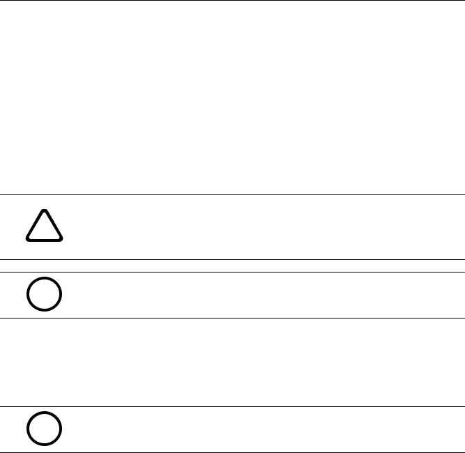
2.Enter the IP address of the VIP XD as the URL. The connection is established and after a short time you will see the CONNECTIONS page.
Maximum Number of Connections
If you do not connect, the unit may have reached its maximum number of connections. Depending on the unit and network configuration, each VIP XD can have up to 25 Web browser connections or up to 50 connections via VIDOS or Bosch Video Management System.
DOC | V4.0 | 2009.06 |
Installation and Operating Manual |
Bosch Security Systems |
VIP XD |
Configuration Using a Web Browser | en 23 |
|
|
Protected VIP XD
If the VIP XD is password protected against unauthorized access, the Web browser displays a corresponding message and prompts you to enter the password when you attempt to access protected areas.
NOTICE!
The VIP XD offers the option to limit the extent of access using various authorization levels (see Section 5.4 Password, page 25).
1.Enter the user name and associated password in the corresponding text fields.
2.Click OK. If the password is entered correctly, the Web browser displays the page that was called up.
Protected Network
If a RADIUS server is employed in the network for managing access rights (802.1x authentication), the VIP XD must be configured accordingly, otherwise no communication is possible.
To configure the unit, you must connect the VIP XD directly to a computer using a network cable. This is because communication via the network is not enabled until the Identity and Password parameters have been set and successfully authenticated (see
Section Authentication, page 48).
Bosch Security Systems |
Installation and Operating Manual |
DOC | V4.0 | 2009.06 |
24 en | Configuration Using a Web Browser VIP XD
5.2 Configuration Menu
The SETTINGS page provides access to the configuration menu, which contains all the unit's parameters arranged in groups.
You can view the current settings by opening one of the configuration screens. You can change the settings by entering new values or by selecting a predefined value from a list field. All parameter groups are described in this chapter in the order in which they are listed in the configuration menu, from the top of the screen to the bottom.
CAUTION!
!The settings in the configuration menu should only be processed or modified by expert users or system support personnel.
All settings are backed up in the VIP XD memory so they are not lost even if the power fails.
Navigation
1.Click one of the menu items in the left window margin. The corresponding submenu is displayed.
2.Click one of the entries in the submenu. The Web browser opens the corresponding page.
Making Changes
Each configuration screen shows the current settings. You can change the settings by entering new values or by selecting a predefined value from a list field.
XAfter each change, click Set to save the change.
CAUTION!
!Save each change with the associated Set button.
Clicking the Set button saves the settings only in the current field. Changes in any other fields are ignored.
DOC | V4.0 | 2009.06 |
Installation and Operating Manual |
Bosch Security Systems |
 Loading...