Bosch ZX938Z Installation Manual

Ceiling Mount PIR with POPIT Interface ZX938Z
Installation Guide
Trademark names are used throughout this document. In most cases, these designations are claimed as trademarks or registered trademarks in one or more countries by their respective owners. Rather than placing a trademark symbol in every occurrence of a trademark name, Bosch Security Systems, Inc. (hereinafter referred to as Bosch) uses the names only in an editorial fashion and to the benefit of the trademark owner with no intention of infringing the trademark.
1.0Specifications
•Input Power: Connect to the Zonex Bus of the control panel.
•Current Draw: Less than 600 micro-amps. Four milli-amps when in Walk Test Mode (LED on).
•Standby Power: There is no internal standby battery. Connect to DC power sources capable of supplying standby power if primary power fails. 500 micro-amp-hours required for each hour of standby time needed. Four hours minimum is required for UL Listed Requirements.
•Coverage: 360° by 60 ft. (18.3 m) diameter coverage when mounted on 8 to 18 ft. (2.4 to 5.5 m) high ceilings. Pattern consists of 64 zones grouped into 16 barriers, with one additional zone looking straight down from the unit (sabotage). Each barrier is 30 ft. (9.2 m) long and 4.4 ft. (1.3 m) wide at 30 ft. (9.2 m). Choice of two optical modules depending on ceiling height.
Note: For UL Listed Requirements, the coverage is 360° by 54 ft. (16.5 m) when mounted from 10 to 13 ft. (3.1 to 4.0 m) using the AR8-13 Array and when mounted from 15 to 18 ft. (4.6 to 5.5 m) using the AR13-18 Array.
•Sensitivity: Standard, Intermediate, or High.
•Tamper: A tamper condition is signaled through the Zonex Bus and displayed at the keypads when the cover is removed. Note: After the cover has been installed and twisted into place, the entire assembly can be secured together using the (two) supplied anti-vandal screws.
•Temperature: The storage and operating range is -20° F to +120° F (-29° C to +50° C). For UL Listed Requirements, the range is +32° F to +120° F (0° C to +50° C).
•Requirements: Compatible control panel with POPEX module installed.
•Options: TC6000 Test Cord.
•EN50131-2-2 Grade 2, Environmental Class II
2.0Certifications and Approvals
Region |
Certification |
|
Europe |
CE |
EN50131-1, Grade 2 |
|
|
EN50131-2-2 Grade 2 |
|
|
Environmental Class II |
USA |
UL |
ANSR: Intrusion Detection Units (UL639) |
France |
AFNOR |
NF,A2P |
3.0Programming
Program the address DIP switches as described for the control panel you are using.
Note: When installing the ZX938Z with a D7212B1, D8112, or D9112B1; place switch number “0” in the ON position.
• Recommended point type programming:
D8112 = 7571
D9112B1/D7212B1 = Point type 2, point response 2, no ring until restored.
D9412/D9112 = Point type 2, point response E, no ring until restored.

ZX938Z
4.0Mounting
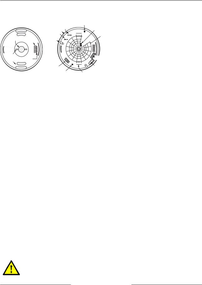
REAR WIRE |
|
ENTRANCE |
TERMINAL |
|
|
|
STRIP |
|
1 |
|
4 |
WIRE |
|
TIE-DOWNS (2) |
|
INTERFACE
MOUNTING PINS
SLOTS (4)
Mounting Base
ANTI-TAMPER SCREW HOLE
REQUIRED FOR EN50131
INSTALLATIONS
SOUNDER |
SIGNAL GAIN |
|
|
CUTOUT |
PINS |
NOISE |
|
OPTICAL |
VOLTAGE |
AR8-13 |
MODULE |
ALARM/TEST
LED
INDICATOR (2)
ON |
ADDRESS |
OFF |
SWITCHES |
|
|
|
AR8-13 |
CONFIGURATION |
COVER |
|
TAMPER |
||
SWITCHES |
||
|
||
ANTI-TAMPER SCREW HOLE |
MODULE TABS (2) |
|
REQUIRED FOR EN50131 |
||
|
||
INSTALLATIONS |
|
1.Select a location that is most likely to intercept an intruder moving across the coverage pattern (review section 12.0 Coverage Patterns, p.4).
The recommended mounting height is 8 to 18 ft. (2.4 to 5.5 m).
Note: To Avoid False Alarm Situations: Do not mount near air handling system outlets, in areas of extreme drafts, or near other potential false alarm situations such as windows, animals, sunlight, and heat and cooling sources.
2.Remove the cover by turning it counterclockwise.
3.Remove the base from the enclosure by pressing the two enclosure release tabs inward while lifting the enclosure away from the base.
HINT: Slightly rock the enclosure side-to-side during removal to overcome the friction caused by the base-to-enclosure terminal pins. 4. Route wiring as necessary to the rear of the base and through the center hole.
Note: Be sure all wiring is unpowered (de-energized) before routing.
5.Firmly mount the base. Depending on local regulations, the base may be directly surface mounted using anchors, mollies, or wing nuts; or may be mounted to standard four-inch octagonal and square electrical boxes.
Note: The ZX938Z base will not completely cover a four-inch square box. Where aesthetics are important, a four-inch octagonal box is recommended.
HINT: Mounting to removable ceiling tiles is not recommended unless a sandwich is made of the base, ceiling tile, and a back plate behind the tile. Covers used for four-inch octagonal and square boxes make a suitable back plate (when used with bolts and wing nuts, as an example).
5.0Selecting the Optical Module (AR8-13 or AR13-18)
1.Replace the enclosure onto the base.
2.Select one of the included optical modules (AR8-13 or AR13-18).
For ceilings between 8 and 13 ft. (2.4 and 4.0 m) from the floor, use the optical module marked AR8-13. This marking can be found next to the two optical module tabs.
For ceilings between 13 and 18 ft. (4.0 and 5.5 m) high, use the optical module marked AR13-18.
3.To replace an optical module, push the optical module tabs towards the center until the module snaps free of the circuit board.
4.Holding the new module by the tabs, snap the new module into place.
Note: Avoid fingerprints on the mirrored surfaces. Should the mirrored surfaces become soiled or otherwise marked, they can be cleaned using a soft, clean cloth and any commonly available, mild window cleaner. Excessive handling of the mirror surfaces may lead to performance degradation.
6.0Wiring
Only apply power after all connections have been made and inspected.
ZX938Z Installation Guide
F01U089251-02a |
Page 2 |
© 2011 Bosch Security Systems, Inc. |
 Loading...