Bosch ZX776Z Installation Manual

Installation Instructions for the
PIR Motion Detector with POPIT Interface
1.0Specifications
•Input Power: Connect to the Zonex Bus of the
control panel.
•Current Draw: Less than 1.7 mA during alarm
condition.
•Standby Power: There is no internal standby battery.
Connect to DC power sources capable of supplying standby power if primary power fails. 1.7 mAh are required for each hour of standby time needed. Four hours
minimum is required for then UL Listed requirements.
• Coverage: |
|
Standard Broad |
15 m by 15 m (50 ft by 50 ft) |
Barrier (Optional): |
24.4 m by 4.8 m (80 ft by 16 ft) |
Long Range (Optional): |
36.6 m by 3.1 m (120 ft by 10 ft) |
•Sensitivity: Standard, Intermediate, or High
•Tamper: A tamper condition is signaled
through the Zonex Bus and displayed at the keypads when the cover is removed.
•Temperature: The storage and operating range is
-29°C to +49°C (-20°F to +120°F). For UL Listed requirements, the range is 0°C to +49°C
(+32°F to +120°F).
•Requirements: Compatible Bosch Security Systems
control panel with the POPEX Module installed.
•Options: B328 Gimbal Mount Bracket,
B335 Low Profile Swivel Mount Bracket, Ceiling Mount Bracket, OMB77-3* Barrier Mirror, OMLR77-3* Long Range Mirror, and the TC6000 Test Cord.
* Shipped in packages of three.
Note: When using an optional mounting bracket, detector misalignment can reduce range.
ï Reading Bosch Security Systems, Inc. Product Date Codes
For Product Date Code information, refer to the Bosch Security Systems, Inc. Web site at: http://www.boschsecurity.com/ datecodes/
2.0Programming
Program the address DIP switches as described for the control panel you are using.
Note: Place switch number 0 in the ON position when installing the ZX776Z with a D7212B1, D8112, or D9112B1.
The recommended point type programming is:
•D8112 = 7571
•D9112B1/D7212B1 = Point type 2, point response 2, no ring until restored
•D9412/D9112 = Point type 2, point response E, no ring until restored
Avoid
Direct Hot and Cold Drafts, Windows,
Small Animals, Air Conditioner Outlets,
Heat Sources, Direct Sunlight
Remember
Does not detect through glass. Best catch performance is across the pattern.
When using two or more detectors, cross patterns for best coverage.
3.0Mounting
•Select a location that is most likely to intercept an intruder moving across the coverage pattern. The recommended mounting height range is 2.0 m to 2.6 m (6.5 ft to 8.5 ft).
Note: Ensure the mounting surface is solid and vibration free.
T-Strip |
|
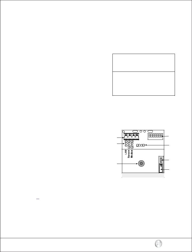
Address |
0 1 2 3 4 5 6 |
Switches |
Program |
|
Plugs |
DO |
NOT USE
|
Noise |
LED |
Voltage |
|
|
|
Tamper |
|
Switch |
Figure 1: Circuit Board Components

|
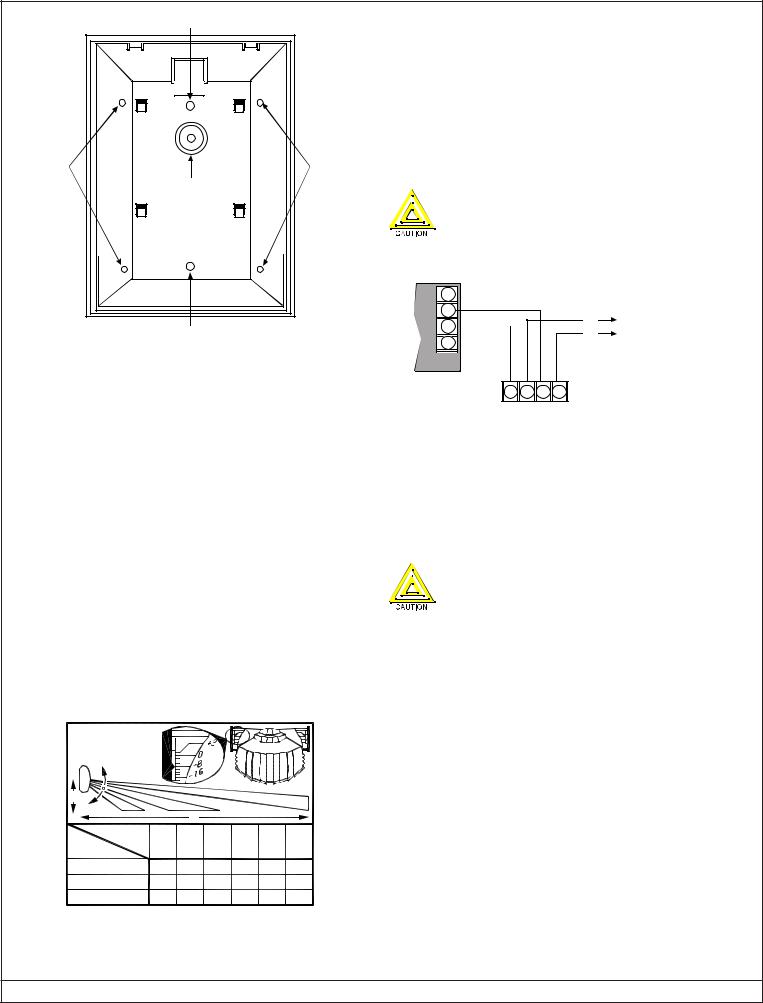
Surface Mounting Hole |
|
Corner |
|
Corner |
Mounting |
|
Mounting |
Hole |
Bracket |
Hole |
|
|
|
|
Mounting Hole |
|
Surface Mounting Hole
Figure 2: Detector Enclosure (Rear View)
•Remove the cover. Insert a thin flathead screwdriver into the notch at the bottom of the cover and pry up.
•Remove the circuit board/mirror unit from the enclosure. Push the board/mirror unit toward the top of the enclosure until it clears its four retainer tabs, then lift it out.
•Open the knockout wire entrance and route the wiring through.
3.1Surface or Corner Mounting
•Open two holes for surface or corner mounting.
•Mark the location for the mounting screws. Use the enclosure as a template. Pre-start the mounting screws.
•Firmly mount the detector.
•Replace the circuit board/mirror unit.
3.2Mirror Alignment
Note: Touching the mirror surfaces can lead to performance degredation.
For the best performance, the mirror must be adjusted vertically for the maximum desired detection range (distance) and mounting height. The angle adjustment markings are located on both sides of the mirror (see Figure 3).
MIRROR
ANGLE
ADJUSTMENT
Y |
|
|
|
|
|
|
|
|
X |
|
|
|
|
X m(ft) |
5 |
7 |
9 |
11 |
13 |
15 |
Y m(ft) |
(16) |
(23) |
(30) |
(36) |
(43) |
(50) |
2.0 (6.5) |
-15° |
-10° |
-8° |
-7° |
-6° |
-5° |
2.3 (7.5) |
-16° |
-12° |
-10° |
-8° |
-7° |
-6° |
2.6 (8.5) |
-17° |
-15° |
-12° |
-10° |
-9° |
-8° |
Figure 3: Mirror Alignment
•Adjust by sliding the mirror forward or backward until the angle adjustment markings are in line with the markers on each side of the frame.
•Use Figure 3 to identify the correct vertical angle based on mounting height (X), mirror type, and maximum range (Y).
•Adjust the mirror horizontally by rotating (aiming) it from side to side.
•Walk test the unit as described in the Section 6.0 Setup and Walk Testing.
4.0Wiring
Only apply power after all connections are made and inspected.
Connect wiring as shown in Figure 4.
POPEX MODULE
– |
|
|
– |
(+) |
|
+ |
||
(–) |
||
+ |
||
|
ZONE EXPANSION LOOP TO OTHER POINTS
1 2 3 4
+ + - -
IN OUT IN OUT
Figure 4: Wiring
4.1Terminal Descriptions
1 (+), 2 (+), 3 (-), and 4 (-): Connect to the Zonex Bus of the control panel. Use no smaller than 0.8 mm (#22 AWG) wire between the detector and the control panel.
5.0Program Jumpers
The LED is only for Walk Test. Disable the LED by turning Switch 1 off for normal operation. Failure to turn off the LED results in a Zonex malfunction.
The following functions are controlled by various settings of the program jumpers:
•LED Operation:
-ON: Allows the LED to operate when activated by alarm.
-OFF: The LED does not operate on alarm.
•Sensitivity Mode:
-Standard: Recommended setting for maximum false alarm immunity. Tolerates environmental extremes on this setting. Not recommended for Long Range or Barrier type patterns. The detector is shipped in Standard Sensitivity Mode.
-Intermediate: Recommended setting for any location where an intruder is expected to cover only a small portion of the protected area. Tolerates normal environments on this setting. This setting improves your intruder catch performance.
-High: Setting for fast response to intruder signals. For use in quiet environments where thermal and illumination transients are not anticipated.
Page 2 |
© 2012 Bosch Security Systems, Inc. |
ZX776Z Installation Instructions |
 Loading...