


Microwave PIR Detector with POPIT Interface ZX835
Installation Instructions
1.0Specifications
•Input Power: 9 to 15 VDC, 6 mA nominal (35 mA with LED on).
•Standby Power: There is no internal standby battery. Connect to standby power as a backup in the event primary power fails. Six mA-H required for each hour of standby time needed. Four hours minimum is required for UL Listed Requirements.
•Temperature: The operating temperature range is -20° to +120°F (-29° to +49°C). For UL Listed Requirements, the temperature range is +32° to +120°F (0° to +49°C).
•Microwave Frequency: 10.525 Ghz, ±25.000 Mhz.
•Coverage: 35 ft. by 35 ft. (10.7 m by 10.7 m)
•Internal Pointability: +2° to –10° Vertical, ±10° Horizontal.
•Tamper: Tamper condition transmitted through the Zonex bus when the cover is removed.
•Requirements: Requires a compatible control panel with a POPEX module installed.
•Options: B328 Gimbal Mount Bracket, B335 Low Profile Swivel Mount Bracket (use of a bracket may reduce range and dead zone areas).
•Reading Bosch Security Systems, Inc. Product Date Codes: For Product Date Code information, refer to the Bosch Security Systems, Inc. Web site at: http://www.boschsecurity.com/datecodes/
2.0Installation Considerations
•Never install the detector in an environment that causes an alarm condition in one technology. Good installations start with the LED OFF when there is no target motion. It should never be left to operate with the tri-color LED in a constant or intermittent green, yellow, or red condition.
•Point the unit away from outside traffic (roads/alleys). Remember: Microwave energy will pass through glass and most common non-metallic construction walls. Avoid installations where rotating machines (e.g., ceiling fans) are normally in operation within the coverage pattern.
•Point the unit away from glass exposed to the outdoors and objects that may change temperature rapidly. Remember: The PIR detector will react to objects rapidly changing temperature within its field-of-view.
•Eliminate interference from nearby outside sources.
3.0Mounting
1. Select a location likely to intercept an intruder moving across the
coverage pattern. The surface should be solid and vibration free. Mounting height range is 6 to 8 ft. (1.8 to 2.4 m). Recommended mounting height is 6.5 ft. (2 m).
2. Remove the cover. Insert a flathead screwdriver into the locking tab hole at the bottom front of the detector. Pull the cover up and forward.
3. Mount the unit with the terminal block up.
4. Remove the circuit board from the base. Loosen the Vertical Adjust Screw and slide the circuit board down then out.
5. Break away the appropriate thin-wall wire entrance and mounting hole coverings in the base.
6. Using the base as a template, mark the location of the holes on the mounting surface.
7. Route wiring (unpowered) as necessary. Route to the rear of the base and through the wire entrance.
8.Firmly mount the base to the mounting surface. Return the circuit board to the base and tighten the Vertical Adjust Screw.
ZX835
4.0Programming
Program the address DIP switches as described for the control panel you are using.
Note: |
When installing the ZX835 with a D7212B1, D8112, or D9112B1; place switch number “0” in the ON position. |
|
|
Recommended point type programming: |
D8112 = 7571 |
|
|
D9112B1/D7212B1 = Point type 2, point response 2, no ring until restored. |
|
|
D9412/D9112 = Point type 2, point response E, no ring until restored. |
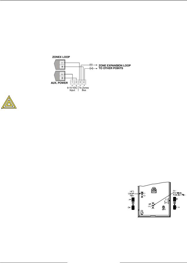
5.0Wiring
Apply power after all connections have been inspected. Do not coil excess wiring inside. Plug the wire entrance hole with the
foam plug provided after all wiring connections have been made.
CAUTION
6.0LED Operation
The detector uses a tri-color LED to indicate the various alarm and supervision trouble conditions that may exist
LED |
CAUSE |
Steady red |
Unit alarm |
Steady yellow |
Microwave activation (walk test) |
Steady green |
PIR activation (walk test) |
Flashing red |
Warm-up period after power-up |
Flashing red (4-pulse sequence) |
Microwave or PIR failure; replace unit |
If the detector experiences a Microwave or PIR self-test failure, it is in need of replacement.
During walk testing, the LED will light for the first technology (microwave or PIR) and then light red to indicate a detector alarm. The LED will not indicate activation of the second technology by lighting its color.
7.0 Feature Selection
• LED On/Off Pins: The ON position allows operation of the tri-color LED. If the tri-color LED indication is not desired after setup and walk tests are completed, place the plug in the OFF position. The OFF position does not prevent the tri-color LED from indicating a supervision trouble condition.
• PIR Sensitivity Selection Pins: The PIR response sensitivity may be selected by placing the plug across the pins marked (STD) for Standard or (INT) for Intermediate mode.
-Standard Sensitivity: The recommended setting for maximum false alarm immunity. Tolerates environmental extremes on this setting.
-Intermediate Sensitivity: The recommended setting for non-pet applications where an intruder is expected to cover only a small portion of the protected area. Tolerates normal environments on this setting. This setting will improve your intruder catch performance. (Recommended for higher mounting heights).
8.0Setup and Walk Tests
Select the vertical starting angle from the chart. To adjust the vertical starting angle for the desired mounting height and range, loosen the vertical adjust screw and slide the board up, to point the angle down. Note the settings on the vertical adjust scale.
ZX835 Installation Instructions
F01U069539-08 |
Page 2 |
© 2011 Bosch Security Systems, Inc. |
 Loading...