


ZX970

Microwave/PIR Intrusion Detector with POPIT Interface
ZX970
Installation Instructions
1.0 Specifications
• Input Power: 9 to 15 VDC, 6 mA nominal (35 mA with LED on)
• Zonex Current Draw: 500 mA
• Standby Power: There is no internal standby battery. Connect to standby power as a backup in the event primary power
fails. For each hour of standby time needed, 6 mAh are required. For Underwriters Laboratories Listed Requirements, four
hours (24 mAh) minimum is required .
• Operating Temperature: -20°F to +120°F (-29°C to +49°C). For UL Listed Requirements, the temperature range is
+32°F to +120°F (0°C to +49°C).
• Microwave Frequency: 10.525 GHz, ±25.000 MHz.
• Coverage: Standard Broad (Included) 70 ft. by 70 ft. (21.4 m by 21.4 m)
Long Range (Optional) 100 ft. by 10 ft. (31 m by 3.1 m)
• Internal Pointability: +2° to -10° Vertical, ±10° Horizontal. Use of the swivel brackets allows for additional pointability.
• Tamper Loop: Tamper condition transmitted through the Zonex Bus when the cover is removed.
• Requirements: Requires a compatible control panel with a POPEX module installed.
• Options: TC6000 Test Cord, B335 Low Profile Swivel Mount Bracket, B328 Gimbal Mount Bracket, B800 Ceiling
Mount Bracket (use of a bracket may reduce range and increase dead zone areas) and OLR92-3* Long Range Lens.
*Shipped in packages of three.
• U.S. Patent Numbers: #4,660,024; #4,764,755; #5,083,106; #5,208,567; # 5,262,783; #5,268,668; #5,302,941; and
#5,450,062. Other patents pending.
Tri-color
LED
Vertical
Adjust
Screw
Terminal
Strip
MW
0°
- 4°
- 8°
Vertical Adju st
Scale
LED
On/Off
Pins
On
Off
Microwave
Range Adjust
_
+
Motion Monitor
and
Anti-Mask
Selection Pins
PIR
Sensitivity
Selection Pins
Microwave Noise Voltage Pins
30
4
INT
STD
Off
PIR Noise
Voltage Pins
Look Down
Mask
_
+
DC Zonex
Address
Switches
Tamper
Switch
0123456
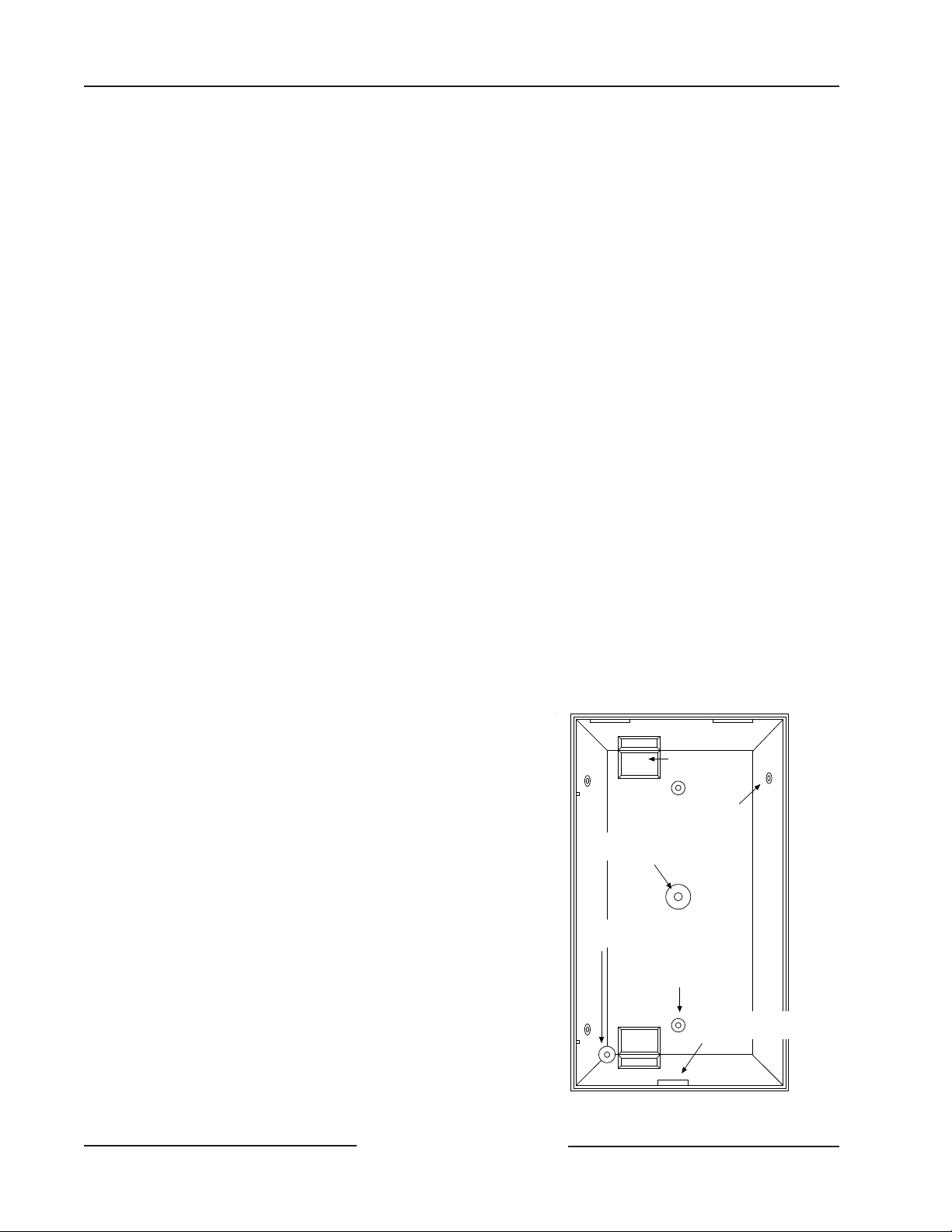
Figure 1: Location of Major Items
ZX970
ZX970 Installation Instructions
Page 2 © 2003 Bosch Security Systems35987G
2.0 Hostile Environments
Never install the detector in an environment that causes a constant alarm in one technology; it should never be left to operate with the
tri-color LED in a constant green, yellow, or red condition. This defeats the main intent of dual technology : elimination of random
false alarms due to the constant alarming of one technology and not the other. A detector with one technology in constant alarm will
cause an alarm output whenever the other technology alarms. Good installations start with the LED OFF when there is no target
motion.
Note: The best installations will have background noise v oltages below recommended limits.
3.0 Installation Hints
• Point the unit AWAY from outside traffic (e.g., roads, alleys, and parking lots). Remember: Microwave energy will pass
through glass and most common non-metallic construction walls.
• Point the unit AWAY from g lass exposed to the outdoors and objects that may change temperature rapidly. Remember:
The PIR detector will react to objects rapidly changing temperature within its field-of-view.
• For hostile environments caused by nearby outdoor traffic, mount the detector 7 to 8 ft. (2 to 2.5 m) high and aim
downward. This will form a short range interior trap pattern while avoiding outdoor traffic. Complete a walk test by
walking next to the walls where the outside traffic is nearest the coverage pattern. Observe the microwave background noise
levels during this walk test. Make sure a significant increase in voltage does not occur while you are outside the coverage
pattern. If the voltage change exceeds 0.75 VDC, reduce the microwave range slightly and walk test again.
• Avoid installations where rotating machines (e.g., ceiling fans) are normally in operation within the coverage pattern.
4.0 Programming
Program the address DIP switches as described for the control panel you are using.
Note: When installing the ZX970 w ith a D7212B1, D8112, or D9112B1; place switch number “0” in the ON position.
Recommended point type programming: D8112 = 7171
D9112B1/D7212B1 = Point type 2, point response 1, no ring until restored.
D9412/D9112 = Point type 2, point response 1, no ring until restored.
5.0 Mounting
1. Select a location likely to intercept an intruder moving across the coverage pattern. The surface should be solid and
vibration free. The mounting height range is 6 to 8 ft.
(1.8 to 2.5 m). The recommended height is 6.5 ft. (2 m).
2. Remove the cover by inserting a thin flathead screwdriver into the
locking tab hole at the bottom front of the detector. Pull the cover
up and forward.
3. Remove the circuit board from the base by loosening the Vertical
Adjust Screw and sliding the circuit board down, then out.
4. Break away the appropriate wire entrance and mounting holes in
the base.
5. Using the base as a template, mark the location of the mounting
holes on the mounting surface. Pre-start the mounting screws.
6. Route wiring as necessary. R o ut e t o the rear of the base and
through the wire entrance. Make sure all wiring is unpowered
before routing.
7. Firmly mount the base to the mounting surface.
8. Return the circuit board to the base and tighten the Ver t ical Adjust
Screw.
9. Place the foam plug (provided) in the wire entrance to eliminate
drafts.
Note: It can als o be mounted to a standard single gang electrical box.
Corner Mount
Knockout (4)
Surface Mount
Knockout (2)
Wire
Entrances
Bracket Mount
Knockout
Vertical Adjust
Screw Mount
Cover Tab and
Locking Screw Hole
(2)
Figure 2: The Base
ZX970
ZX970 Installation Instructions
Page 3© 2003 Bosch Security Systems 35987G
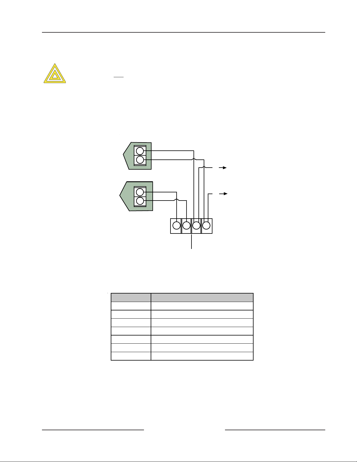
6.0 Wiring
Only apply power after all connections have been made and inspected.
Note: Do not coil excess wiring inside unit.
Wire the terminal strip as shown in Figure 3.
• Terminals 1(–) & 2(+): Power limits are 9 to 15 VDC. Use no smaller than #22 AWG (0.8 mm) wire pair between the unit
and the power source.
• Terminals 3(–) & 4(+): Connect to the Zonex Bus.
Figure 3: Wiring Diagram
7.0 LED Operation
The detector uses a tri-color LED to indicate the various alarm and supervision trouble conditions that may exist.
See Table 1.
Table 1: LED Operation
Note: Flashing red 2 to 4 = The LED flashes 2 to 4 times a cycle.
+
-
+
-
Zonex Loop
Aux. Power
-
+
1234
9-15 VDC
Input
To Zonex
Bus
-
+
Zone Expansion
Loop to other
points
(+)
(-)
CAUTION
LED Cause
Steady red Unit alarm
Steady yellow Microwave activation (walk test)
Steady green PIR activation (walk test)
Flashing red Warm-up calibration period af ter power-up
Flashing red 2 Motion Monitor time-out
Flashing red 3 Microwave Anti-mask detection
Flashing red 4 Microwave or PIR failure. Replace unit.
 Loading...