


LTC 8555-00

© 2003 Bosch Security Systems GmbH
3935 890 11512 03-39 | September 23, 2003 | Data subject to change without notice.
Bosch Security Systems, Inc.
850 Greenfield Road
Lancaster, PA 17601 USA
Tel: 800-326-3270
Fax: 1-717-735-6560
www.boschsecuritysystems.com
Bosch Security Systems B.V.
P.O. Box 80002
5600 JB Eindhoven
The Netherlands
Tele +31 40 27 80000
Bosch Security Systems Pte Ltd.
38C Jalan Pemimpin
Singapore 577180
Republic of Singapore
Tel: 65 (6) 319 3486
LTC 8555 Series
Instruction Manual
EN Allegiant®Keyboards

LTC 8555 Series | Instruction Manual | Important Safeguards
EN
|
2
Bosch Security Systems | 29 August 2003
Important Safeguards
1. Read Instructions - All safety and operating
instructions should be read before the unit is
operated.
2. Retain Instructions - The safety and operating
instructions should be retained for future reference.
3. Heed Warnings - All warnings on the unit and in
the operating instructions should be adhered to.
4. Follow Instructions - All operating and use
instructions should be followed.
5. Cleaning - Unplug the unit from the outlet before
cleaning. Do not use liquid cleaners or aerosol
cleaners. Use a damp cloth for cleaning.
6. Attachments - Do not use attachments not
recommended by the product manufacturer as they
may cause hazards.
7. Water and Moisture - Do not use this unit near
water - for example, in a wet basement, near a
swimming pool, in an unprotected outdoor
installation, or in any area classified as a wet
location.
8. Accessories - Do not place this unit on an unstable
stand, tripod, bracket, or mount. The unit may fall,
causing serious injury to a person and serious
damage to the unit. Use only with a stand, tripod,
bracket, or mount recommended by the
manufacturer or sold with the product. Any
mounting of the unit should follow the
manufacturer's instructions and should use a
mounting accessory recommended by the
manufacturer.
An appliance and cart combination should be
moved with care. Quick stops, excessive force, and
uneven surfaces may cause the appliance and cart
combination to overturn.
9. Ventilation - This unit should not be placed in a
built-in installation or rack, unless proper
ventilation is provided, or the manufacturer’s
instructions have been adhered to. The equipment
must not exceed its maximum operating
temperature requirements.
10.Power Sources - This unit should be operated only
from the type of power source indicated on the
marking label. If you are not sure of the type of
power supply you plan to use, consult your dealer
or local power company. For units intended to
operate from battery power or other sources, refer
to the operating instructions.
11. Grounding or Polarization - This unit may be
equipped with a polarized alternating-current line
plug (a plug having one blade wider than the
other). This plug will fit into the power outlet only
one way. This is a safety feature. If you are unable
to insert the plug fully into the outlet, try reversing
the plug. If the plug should still fail to fit, contact
your electrician to replace your obsolete outlet. Do
not defeat the safety purpose of the polarized plug.
Alternately, this unit may be equipped with a 3wire grounding-type plug, a plug having a third
(grounding) pin. This plug will only fit into a
grounding-type power outlet. This is a safety
feature. If you are unable to insert the plug into the
outlet, contact your electrician to replace your
obsolete outlet. Do not defeat the safety purpose of
the grounding-type plug.
12.Power Cord Protection - Power supply cords should
be routed so that they are not likely to be walked on
or pinched by items placed upon or against them,
paying particular attention to cords and plugs,
convenience receptacles, and the point where they
exit from the appliance.
13.Power Lines - An outdoor system should not be
located in the vicinity of overhead power lines or
other electric light or power circuits or where it can
fall into such power lines or circuits. When
installing an outdoor system, extreme care should
be taken to keep from touching such power lines or
circuits as contact with them might be fatal. U.S.A.
models only - refer to the National Electrical Code
Article 820 regarding installation of CATV systems.
14.Overloading - Do not overload outlets and
extension cords as this can result in a risk of fire or
electric shock.
15. Object and Liquid Entry - Never push objects of
any kind into this unit through openings, as they
may touch dangerous voltage points or short out
parts that could result in a fire or electric shock.
Never spill liquid of any kind on the unit.
16.Servicing - Do not attempt to service this unit
yourself as opening or removing covers may expose
you to dangerous voltage or other hazards. Refer all
servicing to qualified service personnel.

LTC 8555 Series | Instruction Manual |
EN
|
31
Bosch Security Systems | 29 August 2003
Windows®and Windows NT®, are registered trademarks of Microsoft Corporation.
LTC 8555 Series | Instruction Manual | Icon Translator Chart
EN
|
30
Bosch Security Systems | 29 August 2003
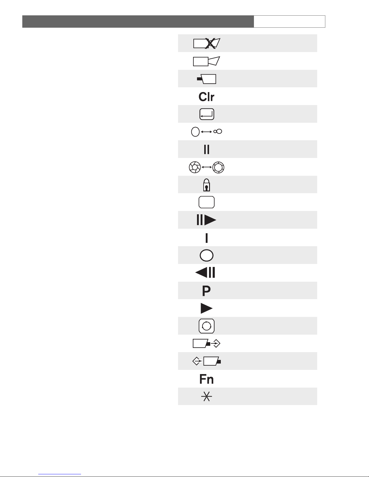
10 ICON TRANSLATOR CHART
(Applies to LTC 8555/01 and LTC 8555/03 keyboard models)
The following chart is used to cross-reference the
text descriptions contained in the manual with the
icons found on keyboard models LTC 8555/01 and
LTC 8555/03.
Ack
Alarm
Camera
Clear
Enter
Focus
Hold
Iris
Lock
Monitor
Next
Off
On
Prev
Prog
Run
Seq
Set
Shot
User
*

LTC 8555 Series | Instruction Manual | FCC & ICES Information
EN
|
3
Bosch Security Systems | 29 August 2003
17. Damage Requiring Service - Unplug the unit from
the outlet and refer servicing to qualified service
personnel under the following conditions:
a. When the power supply cord or plug is
damaged.
b. If liquid has been spilled or objects have fallen
into the unit.
c. If the unit has been exposed to water and/or
inclement weather (rain, snow, etc.).
d. If the unit does not operate normally by
following the operating instructions. Adjust only
those controls that are covered by the operating
instructions, as an improper adjustment of other
controls may result in damage and will often
require extensive work by a qualified technician
to restore the unit to its normal operation.
e. If the unit has been dropped or the cabinet has
been damaged.
f. When the unit exhibits a distinct change in
performance--this indicates a need for service.
18.Replacement Parts - When replacement parts are
required, be sure the service technician has used
replacement parts specified by the manufacturer
or have the same characteristics as the original
part. Unauthorized substitutions may result in fire,
electric shock, or other hazards.
19. Safety Check - Upon completion of any service or
repairs to this unit, ask the service technician to
perform safety checks to determine that the unit is
in proper operating condition.
20.Coax Grounding - If an outside cable system is
connected to the unit, be sure the cable system is
grounded. U.S.A. models only--Section 810 of the
National Electrical Code, ANSI/NFPA No.70,
provides information with respect to proper
grounding of the mount and supporting structure,
grounding of the coax to a discharge unit, size of
grounding conductors, location of discharge unit,
connection to grounding electrodes, and
requirements for the grounding electrode.
21. Lightning - For added protection of this unit during
a lightning storm, or when it is left unattended and
unused for long periods of time, unplug it from the
wall outlet and disconnect the cable system. This
will prevent damage to the unit due to lightning
and power line surges.
FCC & ICES Information
(U.S.A. and Canadian Models Only)
This device complies with part 15 of the FCC Rules.
Operation is subject to the following two conditions:
(1) This device may not cause harmful interference,
and
(2) This device must accept any interference
received, including interference that may cause
undesired operation.
NOTE: This equipment has been tested and found to
comply with the limits for a Class B digital device,
pursuant to Part 15 of the FCC Rules and ICES-003 of
Industry Canada. These limits are designed to provide
reasonable protection against harmful interference
when the equipment is operated in a residential
installation. This equipment generates, uses and can
radiate radio frequency energy, and if not installed and
used in accordance with the instructions, may cause
harmful interference to radio communications.
However, there is no guarantee that interference will
not occur in a particular installation. If this equipment
does cause harmful interference to radio or television
reception, which can be determined by turning the
equipment off and on, the user is encouraged to try to
correct the interf
erence by one or more of the
erence by one or more of the
following measures:
following measures:
• Reorient or relocate the receiving antenna.
• Increase the separation between the equipment and
receiver.
• Connect the equipment into an outlet on a circuit
different from that to which the receiver is
connected.
• Consult the dealer, or an experienced radio/TV
technician for help.
Intentional or unintentional changes or modifications,
not expressly approved by the party responsible for
compliance, shall not be made. Any such changes or
modifications could void the user’s authority to operate
the equipment.
The user may find the following booklet, prepared by
the Federal Communications Commission, helpful:
H
ow to Identify and Resolve Radio-TV Interference
Problems. This booklet is available from the U.S.
Government Printing Office, Washington, DC 20402,
Stock No. 004-000-00345-4.
LTC 8555 Series | Instruction Manual | Safety Precautions
EN
|
4
Bosch Security Systems | 29 August 2003
Safety Precautions
Attention: Installation should be performed by
qualified service personnel only in accordance
with the National Electrical Code or applicable
local codes.
Power Disconnect. Units with or without ONOFF switches have power supplied to the unit
whenever the power cord is inserted into the
power source; however, the unit is operational
only when the ON-OFF switch is in the ON
position. The power cord is the main power
disconnect for all units.
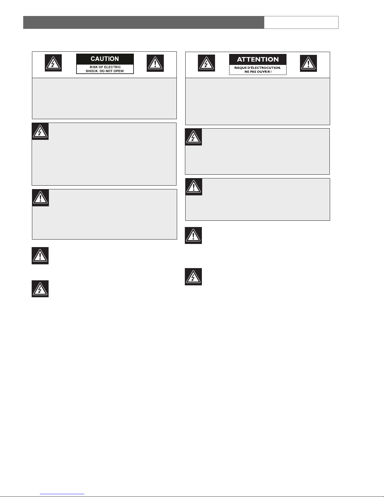
CAUTION: TO REDUCE THE RISK OF
ELECTRIC SHOCK, DO NOT REMOVE COVER
(OR BACK). NO USER SERVICEABLE PARTS
INSIDE. REFER SERVING TO QUALIFIED
SERVICE PERSONNEL.
The lightning flash with an arrowhead
symbol, within an equilateral triangle, is
intended to alert the user to the
presence of uninsulated “dangerous
voltage” within the product’s enclosure
that may be of sufficient magnitude to
constitute a risk of electric shock to
persons.
The exclamation point within an
equilateral triangle is intended to alert
the user to presence of important
operating and maintenance (servicing)
instructions in the literature
accompanying the appliance.
Sécurité
Attention : L’installation doit être exclusivement
effectuée par un technicien spécialisé
conformément à la réglementation du code
national de l’électricité des États-Unis (NEC) ou à
la réglementation locale.
Coupure de l’alimentation. Les appareils avec ou
sans commutateur ON-OFF (marche-arrêt) sont
alimentés dès que le cordon d’alimentation est
branché à la source d’alimentation ; toutefois, les
appareils disposant d’un commutateur de
marche-arrêt ne fonctionnent que lorsque celui-ci
est sur la position ON (marche). Le cordon
d’alimentation est l’organe de coupure principal
de l’alimentation pour tous les appareils.
ATTENTION : POUR ÉVITER TOUT RISQUE
D’ÉLECTROCUTION, NE PAS OUVRIR LE
BOÎTIER. IL N’Y A PAS DE PIÈCES
REMPLAÇABLES À L’INTÉRIEUR. POUR
TOUTE INTERVENTION, S’ADRESSER À UN
RÉPARATEUR PROFESSIONNEL COMPÉTENT.
L’éclair fléché dans un triangle équilatéral
avertit l’utilisateur de la présence d’une
« tension dangereuse » non isolée à
l’intérieur de l’appareil et d’une valeur
suffisante pour constituer un risque
d’électrocution.
Le point d’exclamation contenu dans un
triangle équilatéral avertit l’utilisateur de
la présence, dans la documentation qui
accompagne l’appareil, d’importantes
consignes d’utilisation et de maintenance.

LTC 8555 Series | Instruction Manual | Troubleshooting
EN
|
29
Bosch Security Systems | 29 August 2003
9.2 Local Keyboard Test -Keyboard User Function 1
Keyboard User Function 1 is an Allegiant system
keyboard feature used to verify that all the keyboard’s
LEDs and switches are in working order. This function
also automatically calibrates the center position of the
analog joystick. Upon starting this test, the keyboard
emits a short beep and all LEDs light for about two
seconds. During this time, note any LED failures.
Each key may be pressed to display a unique code
number associated with that key. Follow the table below
to ensure that the keyboard is properly processing all
keys. The amount of deflection of the Joystick during
pan/tilt actions is indicated by a speed indicator value in
the first digit position of the LED display. Rotation of the
Zoom control indicates a value of x41 when rotated
clockwise, and x40 when rotated counterclockwise. Push
USER last, as this exits the keyboard test mode.
If the login system features have been selected by the
system installer, the same local test can be initiated while
the keyboard is not online, by pressing "*" (the star key).
KeyValue
Set 001
Prog 002
Lock 003
Alarm 004
Ack 005
Monitor 008
Shot 009
Digit 1 010
Digit 4 011
Digit 7 012
Digit 0 013
* (Star) 016
On 017
Digit 2 018
Digit 5 019
Digit 8 020
Camera 024
Off 025
KEY VALUE
Digit 3 026
Digit 6 027
Digit 9 028
Enter 029
Seq 032
Run 033
Next 034
Prev 035
Hold 036
Clear 037
Focus (high) 042
Focus (low) 043
Iris (high) 045
Iris (low) 046
(Down) x50
(Right) x51
(Up) x52
(Left) x53
User (enter/exit)

9TROUBLESHOOTING
9.1 General
LTC 8555 Series | Instruction Manual | Troubleshooting
EN
|
28
Bosch Security Systems | 29 August 2003
PROBLEM
No Power Indication
LED Displaying flashing dashes
Non-operating Key or LED digit
Camera and Monitor numbers being displayed, but
Allegiant system will not respond to changes or
P/T/Z controls
Intermittent beeping and/or display of error message
90, 92, 94, or 95.
Possible Causes
a) If powered from a non-modular type Allegiant, try another
keyboard port on the Allegiant. The port may have failed.
b) If powered from a modular type Allegiant, check the fuse on
main Allegiant power supply. Try another keyboard port.
c) If powered from a separate power source, check power
source or main AC supply of power source.
d) If power source is confirmed to be OK, the keyboard may
have an internal failure. Swap suspect keyboard with a
known good keyboard.
a) If the login feature is enabled, the keyboard may be logged
off. (User LED lit and OFF LED lit)
b) If the login feature is not enabled, or the keyboard port is
logged in, there is likely a data communication error. Test the
keyboard cable in another keyboard port. Swap the suspect
keyboard with a known good keyboard. Try another
keyboard data cable. Check keyboard data cable
connections.
c) If using RS-232 protocol models with a dial-up modem link,
the keyboard may be waiting for the operator to dial a phone
number and establish communication with the Allegiant.
a) If a key does not seem to be working, verify that the
attempted function is applicable to the device being
controlled, or the switcher’s current situation.
b) Key or LED may be defective. Run the User Function 1 test
described in section below.
a) Verify that the attempted function is applicable to the device
being controlled, or the switcher’s current situation.
b) If using a directly connected cable, the keyboard port or
keyboard could be defective. Swap the suspect keyboard
with a known good keyboard.
c) If using a communication link other than a directly
connected cable, there could be a problem with the
communication link. Data is being received from the
Allegiant if camera and monitor numbers are displayed, but
these symptoms indicate that the keyboard’s data is not
getting back to the Allegiant. Test with a directly connected
Allegiant keyboard cable. Verify that the communication link
is compatible with Allegiant keyboard data communications.
a) Error 90, Error 92, and Error 94 indicate the Allegiant
system has received invalid data. The most likely cause is
excessive EMI interference on the keyboard data cable,
within the keyboard itself, or possibly in the Allegiant
system. If the keyboard is remoted a long distance, try using
the 3 m (10 ft) data cable supplied with the keyboard.
b) Error 95 indicates that there is intermittent keyboard
communication. Verify the physical data cable connections
and the integrity of the cable connectors.
LTC 8555 Series | Instruction Manual | Safety Precautions
EN
|
5
Bosch Security Systems | 29 August 2003
Sicherheitshinweise
Achtung: Die Installation darf nur von
qualifiziertem Wartungspersonal gemäß dem
National Electrical Code oder den gültigen
örtlichen Vorschriften durchgeführt werden.
Abtrennen der Spannungsversorgung: Die
Spannungsversorgung zu Geräten mit und ohne
Ein/Aus-Schalter ist hergestellt, wenn das
Netzkabel an eine Netzsteckdose angeschlossen
ist. Das Gerät ist jedoch nur betriebsbereit, wenn
der Ein/Aus-Schalter eingeschaltet ist. Bei allen
Geräten erfolgt das Abtrennen der
Spannungsversorgung über das Netzkabel.
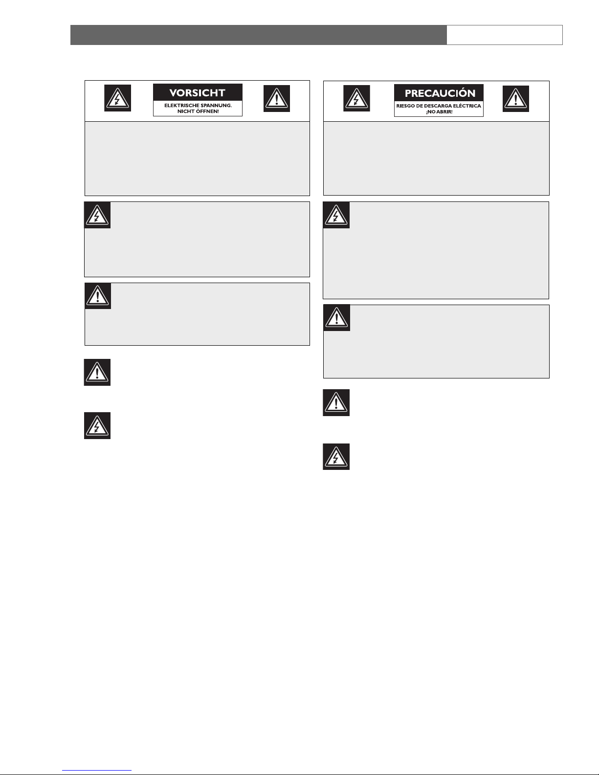
VORSICHT: DAS GEHÄUSE ZUR
VERMEIDUNG VON ELEKTRISCHEN
SCHLÄGEN NICHT ÖFFNEN. DAS GERÄT
ENTHÄLT KEINE VOM BENUTZER ZU
WARTENDEN TEILE. REPARATUREN NUR
VON FACHPERSONAL AUSFÜHREN LASSEN.
Das Blitzsymbol im gleichseitigen Dreieck
soll den Benutzer auf nicht isolierte
“gefährliche Spannung” im Produkt
hinweisen, die ausreichend stark sein kann,
um die Gefahr von elektrischen Schlägen
für Menschen darzustellen.
Das Ausrufungszeichen im gleichseitigen
Dreieck soll den Benutzer auf wichtige
Bedienungs- und Wartungsanweisungen
in der Dokumentation hinweisen, die
dem Gerät beiliegt.
Precauciones de Seguridad
Atención: La instalación debe realizarla
personal cualificado en cumplimiento estricto
del código eléctrico nacional (en el caso de los
EE.UU.) o de los códigos locales aplicables.
Para Desconectar la Alimentación: Unidades
no equipadas con interruptores ON/OFF, son
alimentadas cuando el cable de alimentación es
conectado a la corriente eléctrica. Las unidades
equipadas con interruptores son alimentadas de
igual forma, pero adicionalmente requieren que
el interruptor esté posicionado en ON. El cable
de alimentación es el medio principal de
desconexión del equipo.
PRECAUCIÓN: PARA REDUCIR EL RIESGO
DE DESCARGA ELÉCTRICA, NO ABRA LAS
TAPAS . E N EL INTERIOR NO HAY NINGÚN
COMPONENTE REPARABLE POR EL
USUARIO. LAS REPARACIONES DEBE
REALIZARLAS PERSONAL CUALIFICADO.
El símbolo de flecha en forma de rayo
situado dentro de un triángulo equilátero
pretende alertar al usuario de la presencia
de “voltaje peligroso” sin aislamiento
dentro de la caja del producto, el cual
podría resultar de una magnitud
suficiente como para presentar un riesgo
de descarga eléctrica para las personas.
El punto de exclamación dentro de un
triángulo equilátero pretende alertar al
usuario de la existencia de instrucciones de
funcionamiento y mantenimiento
(reparación) en la documentación
suministrada con el aparato.
 Loading...