


LTC 8500, LTC 8600, LTC 8800
Instruction Manual
EN Allegiant®
Microprocessor-
Based Video
Switcher/Control
Systems
This Instruction Book refers to “TCprefix” model designations. Use this cross-reference to find the new corresponding “LTC-prefix” model numbers. A revised instruction book will be printed at a later date.
LTC 8900 |
TC |
Allegiant® Microprocessor-Based Video Switcher/Control Systems |
LTC 8901/00 |
---- |
Equipment Rack, for LTC 8901 Bay |
LTC 8905/90 |
---- |
Power Supply, 120/220VAC, 50/60Hz |
LTC 8910/00 |
---- |
CPU Module for LTC 8901 Bay |
LTC 8917/00 |
---- |
Relay ("Hot Switch") Module, For LTC 8901 Bay |
LTC 8901/60 |
---- |
CPU Equipment Bay, 120V, 60Hz. Includes: 1 LTC 8901/00, 2 LTC 8905/90, 2 LTC 8910/00, & 1 LTC 8917/00 |
LTC 8901/50 |
---- |
CPU Equipment Bay, 220V, 50Hz. Includes: 1 LTC 8901/00, 2 LTC 8905/90, 2 LTC 8910/00, & 1 LTC 8917/00 |
LTC 8902/00 |
---- |
Equipment Rack, for LTC 8902 Bay |
LTC 8916/00 |
---- |
Data Receiver Module, for LTC 8902 Bay |
LTC 8902/60 |
---- |
Monitor Output Equipment Bay, 120V, 60Hz. Includes: 1 LTC 8902/00, 1 LTC 8805/60 & 1 LTC 8916/00 |
LTC 8902/50 |
---- |
Monitor Output Equipment Bay, 220V, 50Hz. Includes: 1 LTC 8902/00, 1 LTC 8805/50 & 1 LTC 8916/00 |
LTC 8903/00 |
---- |
Equipment Rack, for LTC 8903 Bay |
LTC 8918/00 |
---- |
Data Receiver Module, for LTC 8903 Bay |
LTC 8903/60 |
---- |
Camera Input Equipment Bay, 120V, 60Hz. Includes: 1 LTC 8903/00, 1 LTC 8805/60 & 1 LTC 8918/00 |
LTC 8903/50 |
---- |
Camera Input Equipment Bay, 220V, 50Hz. Includes: 1 LTC8 903/00, 1 LTC 8805/50 & 1 LTC 8918/00 |
LTC 8921/00 |
---- |
Video Input Module, for LTC 8900 System |
LTC 8934/00 |
---- |
Video Output Module, for LTC 8900 System |
LTC 8941/90 |
---- |
PC Package. Includes 1 LTC 8943/90, 2 LTC 8945/90, 1 Monitor, Misc. Cables, 120/220V, 50/60Hz |
LTC 8943/90 |
---- |
PC, Pentium, 120MHz, 40M RAM, 1.6G Drive, Windows NT, 120/220V, 50/60Hz |
LTC 8944/60 |
---- |
PC, Pentium, 120MHz, 40M RAM, 1.6G Drive, Windows NT, 120/220V, 50/60Hz |
LTC 8945/90 |
---- |
LAN Hub, 12-Port, SNMP, 120/220V, 50/60Hz |
LTC 8946/90 |
---- |
Expansion LAN Hub, 12-Port, 120/220V, 50/60Hz |
LTC 8800 |
TC8800 |
Allegiant® Microprocessor-Based Video Switcher/Control Systems |
LTC 8800/00 |
TC8802R |
Equipment Rack, for LTC 8801 Bay |
LTC 8801/60 |
TC8801A |
Main Switching Bay, 120V, 60Hz |
LTC 8801/00 |
TC8801R |
Equipment Rack, for LTC 8801 Bay |
LTC 8801/50 |
TC8801AX |
Main Switching Bay, 220V, 50Hz |
LTC 8802/60 |
TC8802A |
Monitor Expansion Bay, 120V, 60Hz |
LTC 8802/50 |
TC8802AX |
Monitor Expansion Bay, 220V, 50Hz |
LTC 8805/60 |
TC8805 |
Power Supply, 120V, 60Hz |
LTC 8805/50 |
TC8805X |
Power Supply, 220V, 50Hz |
LTC 8821/00 |
TC8821 |
Video Input Module, for LTC 8800 System |
LTC 8834/00 |
TC8834 |
Video Output Module, for LTC 8800 System |
LTC 8859/00 |
TC8859 |
PC Software Package, for LTC 8800 System |
LTC 8810/00 |
TC8810A |
CPU Module, for LTC 8801 Bay |
LTC 8816/00 |
TC8816A |
Data Receiver Module, for LTC 8802 Bay |
LTC 8808/00 |
TC8808 |
Video Interconnect (Patch) Panel |
LTC 8809/01 |
TC8809 |
16-conductor ribbon cable, 3 ft. length |
LTC 8809/00 |
TC8809-6 |
16-conductor ribbon cable, 6 ft. length |
LTC 8820/00 |
TC8820SE |
Service Extender Card, for LTC 8821 |
LTC 8779/00 |
TC8779SE |
Service Extender Card, for LTC 8810, LTC 8816, LTC 8834 |
LTC 8600 |
TC8600 |
Allegiant® Microprocessor-Based Video Switcher/Control Systems |
LTC 8601/00 |
TC8601R |
Equipment Rack, for LTC 8601 Bay |
LTC 8601/60 |
TC8601A |
Main Switching Bay, 120V, 60Hz |
LTC 8601/50 |
TC8601AX |
Main Switching Bay, 220V, 50Hz |
LTC 8621/00 |
TC8621 |
Video Input Module, for LTC 8600 System |
LTC 8834/00 |
TC8834 |
Video Output Module, for LTC 8600 System |
LTC 8659/00 |
TC8659 |
PC Software Package, for LTC 8600 System |
LTC 8610/00 |
TC8610A |
CPU Module, for LTC 8601 Bay |
LTC 8300 |
TC8300 |
Allegiant® Microprocessor-Based Video Switcher/Control Systems |
LTC 8301/60 |
TC8301 |
Main Switching Bay, 120V, 60Hz |
LTC 8301/50 |
TC8301X |
Main Switching Bay, 220V, 50Hz |
LTC 8359/00 |
TC8359 |
PC Software Package, for LTC 8300 System |
LTC 8500 |
TC8500 |
Allegiant® Microprocessor-Based Video Switcher/Control Systems |
LTC 8501/00 |
TC8501R |
Equipment Rack, for LTC 8501 Bay |
LTC 8501/60 |
TC8501C |
Main Switching Bay, 120V, 60Hz |
LTC 8501/50 |
TC8501CX |
Main Switching Bay, 220V, 50Hz |
LTC 8521/00 |
TC8521VIM |
Video Input Module, for LTC 8500 System |
LTC 8532/00 |
TC8532VOM |
Video Output Module, for LTC 8500 System |
LTC 8505/60 |
TC8505PS |
Power Supply, 120V, 60Hz |
LTC 8505/50 |
TC8505PSX |
Power Supply, 220V, 50Hz |
LTC 8511/00 |
TC8511C |
CPU Module |
LTC 8559/00 |
TC8559 |
PC Software Package, for LTC 8500 System |
LTC |
TC |
LTC 8550/00 |
TC8550A |
LTC 8551/00 |
TC8551A |
LTC 8552/00 |
TC8553-232 |
LTC 8553/00 |
TC8553 |
LTC 8554/00 |
TC8554 |
LTC 8555/00 |
TC8555 |
LTC 8558/00 |
TC8557HL |
LTC 8557/60 |
TC8557HR |
LTC 8557/50 |
TC8557HRX |
LTC 9050/00 |
TC8557MK |
LTC 8540/00 |
TC8540C |
LTC 8568/00 |
TC8568 |
LTC 8768/00 |
TC8768 |
LTC 8569/60 |
TC8569-2 |
LTC 8569/50 |
TC8569X-2 |
LTC 8570/60 |
TC8569-4 |
LTC 8570/50 |
TC8569X-4 |
LTC 8571/60 |
TC8769-2 |
LTC 8571/50 |
TC8769X-2 |
LTC 8572/60 |
TC8769-4 |
LTC 8572/50 |
TC8769X-4 |
Allegiant® System Accessories
Keyboard, Joystick Control
Keyboard, Push Button Control
Keyboard, Variable Speed, RS-232, Joystick Control
Keyboard, Variable Speed, Joystick Control
Keyboard, Compact, Push Button Control
Keyboard, Compact, Variable Speed Joystick Control
Keyboard Cable, 100 ft.
Hook-up Kit for Remote Keyboard up to 5,000 ft, 120V. Hook-up Kit for Remote Keyboard up to 5,000 ft, 220V
Rack Mount Kit, for LTC 8550, LTC 8551, LTC 8553 Keyboards
Alarm Interface Unit
Signal Distribution Unit, 32 Outputs
Signal Distribution Unit, 64 Outputs
Code Merger Unit, 2-Channel, 120V, 60Hz
Code Merger Unit, 2-Channel, 220V, 50Hz
Code Merger Unit, 4-Channel, 120V, 60Hz
Code Merger Unit, 4-Channel, 220V, 50Hz
Code Merger Unit, 2-Channel, 120V, 60Hz
Code Merger Unit, 2-Channel, 220V, 50Hz
Code Merger Unit, 4-Channel, 120V, 60Hz
Code Merger Unit, 4-Channel, 220V, 50Hz
LTC 8560/60 |
TC8560-1 |
Receiver/Driver, 120V Supply, 120V to P/T, No Aux. |
LTC 856260 |
TC8560-2 |
Receiver/Driver, 120V Supply, 24V to P/T, No Aux. |
LTC 8562/50 |
TC8560X-2 |
Receiver/Driver, 220V Supply, 220V to P/T, No Aux. |
LTC 8560/50 |
TC8560X-4 |
Receiver/Driver, 220V Supply, 220V to P/T, No Aux. |
LTC 8561/60 |
TC8561A-1 |
Receiver/Driver, 120V Supply, 120V to P/T, with Aux. |
LTC 8566/60 |
TC8561A-2 |
Receiver/Driver, 120V Supply, 24V to P/T, with Aux. |
LTC 8566/50 |
TC8561AX-2 |
Receiver/Driver, 220V Supply, 220V to P/T, with Aux. |
LTC 8561/50 |
TC8561AX-4 |
Receiver/Driver, 220V Supply, 220V to P/T, with Aux. |
LTC 8563/20 |
TC8563 |
Receiver/Driver, 24V Supply, 24V to P/T, No Aux. |
LTC 8564/20 |
TC8564A |
Receiver/Driver, 24V Supply, 24V to P/T, with Aux. |
LTC 8780/60 |
TC8780 |
Time/Date Converter Unit, GPS Format, 120V, 60Hz |
LTC 8780/50 |
TC8780X |
Time/Date Converter Unit, GPS Format, 220V, 50Hz |
LTC 8781/60 |
TC8781 |
Time/Date Converter Unit, GPS Format, 120V, 60Hz |
LTC 8781/50 |
TC8781X |
Time/Date Converter Unit, GPS Format, 220V, 50Hz |
LTC 8785/60 |
TC8785 |
Data Converter Unit, Var. Speed to Fixed Speed Code, 120V, 60Hz |
LTC 8785/50 |
TC8785X |
Data Converter Unit, Var. Speed to Fixed Speed Code, 220V, 50Hz |
LTC 8712/60 |
TC8712A |
Console Port Expander, 120V, 60Hz |
LTC 8712/50 |
TC8712AX |
Console Port Expander, 220V, 50Hz |
LTC 8713/60 |
TC8713A |
Alarm Port Expander, 120V, 60Hz |
LTC 8713/50 |
TC8713AX |
Alarm Port Expander, 220V, 50Hz |
LTC 8714/60 |
TC8714A |
Keyboard Port Expander, 120V, 60Hz |
LTC 8714/50 |
TC8714AX |
Keyboard Port Expander, 220V, 50Hz |
LTC 8715/60 |
TC8715A |
LTC 8714 Port Expander, 120V, 60Hz |
LTC 8715/50 |
TC8715AX |
LTC 8714 Port Expander, 220V, 50Hz |
LTC 8059/00 |
TC8059 |
PC Software Package, for Satellite |
LTC 8850/00 |
TC8850 |
Graphical User Interface (GUI) Package |

IMPORTANT SAFEGUARDS
1.Read Instructions - All the safety and operating instructions should be read before the unit is operated.
2.Retain Instructions - The safety and operating instructions should be retained for future reference.
3.Heed Warnings - All warnings on the unit and in the operating instructions should be adhered to.
4.Follow Instructions - All operating and use instructions should be followed.
5.Cleaning - Unplug the unit from the outlet before cleaning. Do not use liquid cleaners or aerosol cleaners. Use a damp cloth for cleaning.
6.Attachments - Do not use attachments not recommended by the product manufacturer as they may cause hazards.
7.Water and Moisture - Do not use this unit near water - for example, near a bath tub, wash bowl, kitchen sink, or laundry tub, in a wet basement, near a swimming pool, in an unprotected outdoor installation, or any area which is classified as a wet location.
8.Accessories - Do not place this unit on an unstable stand, tripod, bracket, or mount. The unit may fall, causing serious injury to a person and serious damage to the unit. Use only with a stand, tripod, bracket, or mount recommended by the manufacturer, or sold with the product. Any mounting of the unit should follow the manufacturer's instructions, and should use a mounting accessory recommended by the manufacturer.
An appliance and cart combination should be moved with care. Quick stops, excessive force, and uneven surfaces may cause the appliance and cart combination to overturn.
9.Ventilation - Openings in the enclosure, if any, are provided for ventilation and to ensure reliable operation of the unit and to protect it from overheating. These openings must not be blocked or covered. This unit should not be placed in a built-in installation unless proper ventilation is provided or the manufacturer's instructions have been adhered to.
10.Power Sources - This unit should be operated only from the type of power source indicated on the marking label. If you are not sure of the type of power supply you plan to use, consult your appliance dealer or local power company. For units intended to operate from battery power, or other sources, refer to the operating instructions.
11.Grounding or Polarization - This unit may be equipped with a polarized alternating-current line plug (a plug having one blade wider than the other). This plug will fit into the power outlet only one way. This is a safety feature. If you are unable to insert the plug fully into the outlet, try reversing the plug. If the plug should still fail to fit, contact your electrician to replace your obsolete outlet. Do not defeat the safety purpose of the polarized plug.
Alternately, this unit may be equipped with a 3-wire grounding-type plug, a plug having a third (grounding) pin. This plug will only fit into a grounding-type power outlet. This is a safety feature. If you are unable to insert the plug into the outlet, contact your electrician to replace your obsolete outlet. Do not defeat the safety purpose of the grounding-type plug.
12.Power-Cord Protection - Power-supply cords should be routed so that they are not likely to be walked on or pinched by items placed upon or against them, paying particular attention to cords and plugs, convenience receptacles, and the point where they exit from the appliance.
13.Power Lines - An outdoor system should not be located in the vicinity of overhead power lines or other electric light or power circuits, or where it can fall into such power lines or circuits. When installing an outdoor system, extreme care should be taken to keep from touching such power lines or circuits as contact with them might be fatal. U.S.A. models only - refer to the National Electrical Code Article 820 regarding installation of CATV systems.
14.Overloading - Do not overload outlets and extension cords as this can result in a risk of fire or electric shock.
15.Object and Liquid Entry - Never push objects of any kind into this unit through openings as they may touch dangerous voltage points or short-out parts that could result in a fire or electric shock. Never spill liquid of any kind on the unit.
16.Servicing - Do not attempt to service this unit yourself as opening or removing covers may expose you to dangerous voltage or other hazards. Refer all servicing to qualified service personnel.
17.Damage Requiring Service - Unplug the unit from the outlet and refer servicing to qualified service personnel under the following conditions:
a.When the power-supply cord or plug is damaged.
b.If liquid has been spilled, or objects have fallen into the unit.
c.If the unit has been exposed to rain or water.
d.If the unit does not operate normally by following the operating instructions. Adjust only those controls that are covered by the operating instructions, as an improper adjustment of other controls may result in damage and will often require extensive work by a qualified technician to restore the unit to its normal operation.
e.If the unit has been dropped or the cabinet has been damaged.
f.When the unit exhibits a distinct change in performance--this indicates a need for service.
18.Replacement Parts - When replacement parts are required, be sure the service technician has used replacement parts specified by the manufacturer or have the same characteristics as the original part. Unauthorized substitutions may result in fire, electric shock or other hazards.
19.Safety Check - Upon completion of any service or repairs to this unit, ask the service technician to perform safety checks to determine that the unit is in proper operating condition.
20.Coax Grounding - If an outside cable system is connected to the unit, be sure the cable system is grounded. U.S.A. models only-- Section 810 of the National Electrical Code, ANSI/NFPA No.701981, provides information with respect to proper grounding of the mount and supporting structure, grounding of the coax to a discharge unit, size of grounding conductors, location of discharge unit, connection to grounding electrodes, and requirements for the grounding electrode.
21.Lightning - For added protection of this unit during a lightning storm, or when it is left unattended and unused for long periods of time, unplug it from the wall outlet and disconnect the cable system. This will prevent damage to the unit due to lightning and power-line surges.
FCC & ICES INFORMATION
(U.S.A. and Canadian Models Only)
WARNING - This equipment has been tested and found to comply with the limits for a Class B digital device, pursuant to Part 15 of the FCC Rules and ICES-003 of Industry Canada. These limits are designed to provide reasonable protection against harmful interference when the equipment is operated in a residential installation. This equipment generates, uses and can radiate radio frequency energy and, if not installed and used in accordance with the instructions, may cause harmful interference to radio communications. However, there is no guarantee that interference will not occur in a particular installation. If this equipment does cause harmful interference to radio or television reception, which can be determined by turning the equipment off and on, the user is encouraged to try to correct the interference by one or more of the following measures:
-Reorient or relocate the receiving antenna.
-Increase the separation between the equipment and receiver.
-Connect the equipment into an outlet on a circuit different from that to which the receiver is connected.
-Consult the dealer or an experienced radio/TV technician for help.
Intentional or unintentional changes or modifications not expressly approved by the party responsible for compliance shall not be made. Any such changes or modifications could void the user's authority to operate the equipment.
The user may find the following booklet prepared by the Federal Communications Commission helpful: "How to Identify and Resolve Radio-TV Interference Problems". This booklet is available from the U.S. Government Printing Office, Washington, DC 20402, Stock No.004-000- 00345-4.
3
SAFETY PRECAUTIONS
CAUTION
RISK OF ELECTRIC
SHOCK. DO NOT OPEN!
CAUTION: TO REDUCE THE RISK OF ELECTRICAL SHOCK, DO NOT OPEN COVERS. NO USER SERVICEABLE PARTS INSIDE. REFER SERVICING TO QUALIFIED SERVICE PERSONNEL.
This label may appear on the bottom of the unit due to space limitations.
The lightning flash with an arrowhead symbol, within an equilateral triangle, is intended to alert the user to the presence of uninsulated "dangerous voltage" within the product's enclosure that may be of sufficient magnitude to constitute a risk of electric shock to persons.
The exclamation point within an equilateral triangle is intended to alert the user to presence of important operating and maintenance (servicing) instructions in the literature accompanying the appliance.
Warning
To prevent fire or shock hazard, do not expose units not specifically designed for outdoor use to rain or moisture.
ATTENTION
OBSERVE PRECAUTIONS
FOR HANDLING
ELECTROSTATIC
SENSITIVE
DEVICES
WARNING: Electrostatic-sensitive device. Use proper CMOS/MOSFET handling precautions to avoid electrostatic discharge.
NOTE: Grounded wrist straps must be worn and proper ESD safety precautions observed when handling the electrostatic-sensitive printed circuit boards.
Power
Power Disconnect. Units with or without ON-OFF switches have power supplied to the unit whenever the power cord is inserted into the power source; however, the unit is operational only when the ONOFF switch is in the ON position. The power cord is the main power disconnect for all units.
Disjonction de l'alimentation. Les appareils avec ou sans commutateurs ONOFF sont alimentés à chaque fois que le cordon d'alimentation est branché à la source d'alimentation; toutefois, les appareils disposant de commutateurs ONOFF ne fonctionnnent que lorsque le commutateur ON-OFF est sur la position ON. Le cordon d'alimentation est la disjonction d'alimentation principale pour tous les appareils.
Netzanschluß. Geräte mit oder ohne Netzschalter haben Spannung am Gerät anliegen, sobald der Netzstecker in die Steckdose gesteckt wird. Das Gerät ist jedoch nur betriebsbereit, wenn der Netzschalter (EIN/AUS) auf EIN steht. Wenn man das Netzkabel aus der Steckdose zieht, dann ist die Spannungszuführung zum Gerät vollkommen unterbrochen.
Para Desconectar la Alimentación: Unidades no equipadas con interruptores ON/OFF, son alimentadas cuando el cable de alimentación es conectado a la corriente eléctrica. Las unidades equipadas con interruptores son alimentadas de igual forma, pero adicionalmente requieren que el interruptor esté posicionado en ON. El cable de alimentación es el medio principal de desconexión del equipo.
4

TABLE OF CONTENTS
UNPACKING .......................................................... |
6 |
SERVICE ................................................................ |
6 |
DESCRIPTION ....................................................... |
6 |
ALLEGIANT FEATURE SUMMARY TABLE .......... |
7 |
MAJOR SYSTEM COMPONENTS ......................... |
9 |
TC8x01 Main CPU Bay............................................................. |
9 |
TC8802 Monitor Expansion Bay ................................................ |
9 |
TC8x21 Video Input Module ...................................................... |
9 |
TC8532, TC8834 Video Output Modules................................... |
9 |
System Capabilities .................................................................. |
9 |
SUPPLEMENTARY SYSTEM COMPONENTS .... |
10 |
TC8550A System Keyboard.................................................... |
10 |
TC8551A & TC8554 System Keyboards ................................. |
10 |
TC8553 & TC8555 System Keyboards.................................... |
10 |
TC8553-232 System Keyboard ............................................... |
10 |
TC8557MK Keyboard Racking Kit........................................... |
10 |
TC8557HL Keyboard Extension Cable..................................... |
10 |
TC8557HR Series Keyboard Extension Kits ............................ |
10 |
TC8568 Signal Distribution Unit .............................................. |
10 |
TC8768 Signal Distribution Unit .............................................. |
10 |
TC8540C Series Alarm Interface Units.................................... |
10 |
TC8560, TC8561A, TC8563, & TC8564A Series |
|
Receiver/Driver Units........................................................ |
10 |
TC700 Series AutoDomes™ ................................................... |
11 |
TC8569-2, TC8569-4, TC8769-2, TC8769-4 Series ................ |
11 |
TC8770 Switcher Follower Series, TC8770SF, TC8770SG, |
|
TC8770LD, TC8770LG Function Modules......................... |
11 |
TC8770I Interconnect Panel.................................................... |
11 |
TC8712A Series Console Port Expander Units ........................ |
11 |
TC8713A Series Alarm Port Expander Units .......................... |
11 |
TC8714A, TC8715A Series Keyboard Port Expander Units .... |
11 |
TC8780 Series Data Converter Units ...................................... |
12 |
TC8781 Series Time/Data Converters..................................... |
12 |
TC8785 Series Code Converters............................................. |
12 |
Code Translator Units............................................................. |
12 |
TC8808 Video Interconnect Panel ........................................... |
12 |
TC8579SE Service Extender Card .......................................... |
12 |
TC8779SE Service Extender Card .......................................... |
13 |
TC8820SE Service Extender Card .......................................... |
13 |
TC8x59 Series Allegiant Master Control Software.................... |
13 |
Windows Based Allegiant Software ......................................... |
13 |
Logging Printer....................................................................... |
13 |
INSTALLATION PROCEDURE ............................ |
20 |
Main CPU Bay Installation....................................................... |
20 |
Video Input Modules ............................................................... |
20 |
Video Output Modules ............................................................ |
21 |
CPU Module........................................................................... |
21 |
Camera and Monitor Connections ........................................... |
21 |
TC8600 and TC8800 Video Inputs .......................................... |
22 |
Termination Practices ............................................................. |
22 |
TC8802 Expansion Bay Connections ...................................... |
22 |
Keyboard Hookup................................................................... |
23 |
Satellite Configuration Installations .......................................... |
23 |
Feature Selection.................................................................... |
26 |
Main Power Connections ........................................................ |
26 |
OPTIONAL ACCESSORIES................................. |
30 |
Logging Printer Option Installation........................................... |
30 |
IBM or IBM Compatible Computer Interface Installation............ |
30 |
SYSTEM KEYBOARDS - TC8550A, TC8551A, |
|
TC8553 Series ................................................ |
31 |
Keyboard Displays.................................................................. |
31 |
Keyboard Controls.................................................................. |
32 |
Switcher Control Keys ............................................................ |
32 |
Function Keys ........................................................................ |
32 |
Telemetry Controls ................................................................. |
33 |
SYSTEM KEYBOARDS - TC8554, TC8555.......... |
34 |
Keyboard Displays.................................................................. |
35 |
Keyboard Controls.................................................................. |
35 |
Switcher Control Keys ............................................................ |
36 |
Function Keys ........................................................................ |
36 |
Telemetry Controls ................................................................. |
36 |
VIDEO MONITOR DISPLAY................................. |
37 |
Time/Date .............................................................................. |
37 |
Monitor Title/System Status Display ........................................ |
37 |
Monitor Message.................................................................... |
39 |
Broadcast Message................................................................ |
39 |
Program Prompts ................................................................... |
39 |
Camera Number..................................................................... |
39 |
Camera Title........................................................................... |
39 |
FACTORY DEFAULT SETTINGS ........................ |
40 |
User Selectable DIP Switch Settings For Main CPU Bay ......... |
40 |
User Selectable DIP Switch Settings for TC8816A Data |
|
Receiver Modules used in TC8802 Monitor Expansion |
|
Bays ................................................................................ |
42 |
USER INFORMATION.......................................... |
43 |
User Priority Access Table...................................................... |
43 |
ALARM INFORMATION ....................................... |
44 |
Basic Alarm Response Mode .................................................. |
44 |
Auto-Build Alarm Response Mode........................................... |
44 |
Sequence & Display Alarm Response Mode............................ |
44 |
Alarm Activated Pre-Position................................................... |
44 |
Sample Alarm Responses....................................................... |
45 |
KEYBOARD OPERATING INSTRUCTIONS ........ |
47 |
General .................................................................................. |
47 |
System Commands ................................................................ |
47 |
Switcher Commands .............................................................. |
48 |
SEQUENCE INFORMATION ................................ |
48 |
General .................................................................................. |
48 |
Sequence Control Instructions ................................................ |
51 |
Lock Commands .................................................................... |
53 |
Controlling Camera Movement ................................................ |
54 |
Alarm Control Commands....................................................... |
56 |
KEYBOARD USER FUNCTIONS ......................... |
58 |
General .................................................................................. |
58 |
MAINTENANCE INFORMATION.......................... |
64 |
CHARACTER ROM TABLES FOR TC8500 ......... |
65 |
CHARACTER ROM TABLES FOR TC8600 |
|
AND TC8800 ................................................... |
66 |
QUICK REFERENCE KEYBOARD COMMAND |
|
TABLE............................................................. |
70 |
ERROR MESSAGES ............................................ |
71 |
TROUBLESHOOTING GUIDE ............................. |
73 |
GLOSSARY OF TERMS ...................................... |
75 |
APPENDIX A ........................................................ |
76 |
Satellite Systems.................................................................... |
76 |
APPENDIX B ........................................................ |
80 |
Sample Keyboard Operating Instructions................................. |
80 |
APPENDIX C ........................................................ |
83 |
Installation Checklists ............................................................. |
83 |
APPENDIX D ........................................................ |
84 |
Quick Reference Cable Interconnections................................. |
84 |
APPENDIX E ........................................................ |
85 |
Main Bay Rear Panel Connector Pinouts ................................. |
85 |
APPENDIX F ........................................................ |
86 |
Pre-Position Controls.............................................................. |
87 |
5
UNPACKING |
|
The TC8500 Series Allegiant system can handle up |
|
|
to 64 cameras and 8 monitors in a full crosspoint |
||
Unpack carefully. This is electronic equipment and |
configuration. It can also accommodate 128 alarm |
||
points. |
|||
should be handled carefully. |
|
||
|
|
||
If an item appears to have been damaged in |
The TC8600 Series handles up to 128 cameras, 16 |
||
monitors, and 512 alarms. |
|||
shipment, replace it properly in its carton and notify |
|||
|
|||
the shipper. If any items are missing, |
notify your |
The TC8800 Series handles 256 cameras, 64 |
|
Bosch Security Systems, Inc. Sales |
Representative monitors, and up to 1024 alarm points. |
||
or Customer Service.
The shipping carton is the safest container in which the unit may be transported. Save it for possible future use.
SERVICE
If the unit ever needs repair service, the customer should contact the nearest Bosch Security Systems, Inc. for authorization return and shipping
instructions.
Service Centers
U.S.A.: 800-366-2283 or 717-735-6638 Fax: 800-366-1329 or 717-735-6639 CCTV Spare Parts
U.S.A: 800-894-5215 or 408-956-3853 or 3854 Fax: 408-957-3198
In addition, the Allegiant series have a "Satellite" configuration capability through which the system can communicate with up to 256 remote combinations of Allegiant systems or TC8112B Series and TC8124B Series switchers. More information on this capability is provided later in this manual.
The system can be operated in the simple default state (as it leaves the factory) or can be customized with our optional TC8850 Graphical User Interface Software package or our optional TC8x59 Master Control Software using an IBMTM or IBM compatible personal computer. Despite its sophistication, the Allegiant system is designed for the novice user. The ergonomic keyboard design contains many userfriendly but powerful functions. A user can choose from up to 60 sequences that are stored in memory, select any of the cameras to view on any of the monitors, and take exclusive control of remote pan/tilt camera functions right from the keyboard.
DESCRIPTION
This manual covers the installation and operation of the Allegiant® TC8500 Series, TC8600 Series, and TC8800 Series systems. When providing information that is common to all members of the Allegiant family, this manual will often use a part number of the form "TC8x00". The "x" indicates that this designation applies to all Allegiant systems. For example, information that refers to the TC8x01 main CPU bay is applicable to the TC8501, TC8601, and TC8801. A specific part designation (without the embedded “x”) like "TC8802 Monitor Expansion Bay" will usually apply only to that particular series of the Allegiant family. An exception is that peripherals that are identical on all systems will often have a TC8500 Series part number. For example, the TC8550A Keyboard, the TC8568 Signal Distribution Unit, and the TC8569-2 Series Code Merger are used with all Allegiant systems even though they have a TC8500 Series part number.
All Allegiant systems can accommodate multiple keyboards, a computer system console port, and a logging printer output.
Each monitor can display a system status overlay showing alarm status, sequence conditions, time/date, and camera information.
User passwords can be utilized, providing an added measure of system security; and through the optional TC8850 Graphical User Interface Software package or the optional Master Control Software package, various lockout tables restricting user access to cameras, monitors, keyboards, and remote camera control are easily programmed. The TC8850 Graphical User Interface Software package and the Master Control Software package also contain up to 64 different time-activated events, providing automated control of video sequencing, monitor message broadcasts, receiver/driver functions, alarm control, and several other functions. The Allegiant series systems represent a dramatic breakthrough in CCTV switcher/controllers, and are backed by years of expertise in designing and manufacturing closedcircuit video equipment.
6
ALLEGIANT FEATURE SUMMARY TABLE
The Allegiant system is available in two operating configurations: a base system and the base system with an optional PC based software package (either TC8850 or TC8x59). The base system includes features required for most switching/controller systems.
The addition of the optional TC8850 Graphical User Interface Software package or the optional TC8x59 Master Control Software package enables the user to customize the system's configuration using a menu driven program run on an IBM compatible personal computer.
The following table lists the various features available with each system:
Feature |
Base |
With Optional |
|
|
|
Allegiant |
PC based |
|
|
System |
Software |
1. |
Full camera switching/control on all monitors |
Y |
Y |
2. |
Multiple keyboards |
Y |
Y |
|
(8 with TC8500, 16 with TC8600, 32 with TC8800) |
|
|
3. |
Multiple alarm inputs |
Y |
Y |
|
(128 with TC8500, 512 with TC8600, 1024 with TC8800) |
|
|
4. |
3 user-selectable pre-defined alarm response modes |
Y |
Y |
5. |
Full control of on-site receiver/drivers |
Y |
Y |
6. |
SalvoSwitching® |
Y |
Y |
7. |
60 programmable sequences |
Y |
Y |
8. |
Alarm call-up of pre-position scenes |
Y |
Y |
9. |
RS-232 interface ports for Computer, Logging Printer, etc. |
Y |
Y |
10. |
Keyboard Log-on/Log-off function |
Y |
Y |
11. |
User-selectable password security |
Y |
Y |
12. |
Designate 16-character camera titles and 12-character monitor titles |
Y |
Y |
13. |
Select time/date format |
Y |
Y |
14. |
Local keyboard test function |
Y |
Y |
15. |
Table and Sequence printout feature |
Y |
Y |
16. |
Designate RS-232 communication parameters |
Y |
Y |
17. |
Integral video loss detection (TC8600 and TC8800) |
N |
Y |
18 |
Satellite configurations |
N |
Y |
19. |
Restrict user/keyboard access to cameras |
N |
Y |
20. |
Restrict user/keyboard access to receiver/drivers |
N |
Y |
21. |
Restrict user access to keyboard |
N |
Y |
22. |
Restrict user/keyboard access to monitors |
N |
Y |
23. |
Designate user name and ID number |
N |
Y |
24. |
Designate zoned alarm call-ups |
N |
Y |
25. |
VersAlarmTM alarm feature |
N |
Y |
26. |
Designate displayed camera number |
N |
Y |
27. |
Designate receiver/driver functions on alarm |
N |
Y |
28. |
Program 64 Time Activated Events |
N |
Y |
29. |
Designate receiver/driver functions in sequences |
N |
Y |
30. |
Broadcast monitor messages |
N |
Y |
31. |
Alarm title designation |
N |
Y |
32. |
Personal computer displayed monitoring of system status |
N |
Y |
33. |
Personal computer emulation of system keyboard |
N |
Y |
7
In addition, all systems provide the capability to control on-site receiver/driver units including the AutoDome™ series of integral pan/tilt/zoom/camera dome series.
All systems contain a logging printer output port to which an inexpensive RS-232 serial printer may be attached. This provides a permanent record showing time and date of changes to the system status such as:
1.Incoming Alarms.
2.Acknowledgment of alarms by users.
3.Loading of sequences.
4.User log-on to keyboard or console port.
5.Console broadcast message.
6.Console transfer of system tables.
7.Activation of Time Event Functions.
8.Power-up reset message.
9.Video loss message (TC8600 and TC8800 systems only).
The printer may also be used to provide a hard copy of all user programmed system configuration Tables and Sequences.
8
MAJOR SYSTEM COMPONENTS
TC8x01 Main CPU Bay
A modular equipment bay which contains the system’s microprocessor module (TC8511C or TC8x10A), the power supply module (TC8x05), and several video input and video output modules (see below). Up to eight TC8550 Series keyboards may be connected directly to the CPU bay.
TC8802 Monitor Expansion Bay
Required in TC8800 systems having more than 32 monitors. This expansion bay contains a data receiver module (TC8816A), a power supply (TC8805), and additional video input and output modules. The monitor expansion bay can also accommodate up to eight additional keyboards.
TC8x21 Video Input Module
Individual cards placed in bays to accept inputs from cameras and other video sources.
TC8532, TC8834
Video Output Modules
Individual cards placed in bays to provide outputs to monitors and VCRs.
System Capabilities
These tables indicate the maximum number of video input and output modules that each equipment bay may hold, as well as the number of individual inputs or outputs supported by each of these modules.
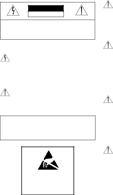
TC8500
Up to 8 video input modules; 8 inputs per module. Up to 4 video output modules; 2 outputs per module. Total: 64 maximum inputs; 8 outputs.
Satellite configuration input capacity: 320.
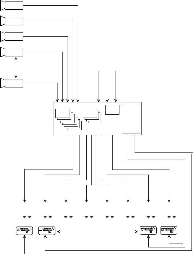
TC8600
Up to 8 video input modules; 16 inputs per module. Up to 4 video output modules; 4 outputs per module. Total: 128 maximum inputs; 16 outputs.
Satellite configuration input capacity: 1152.
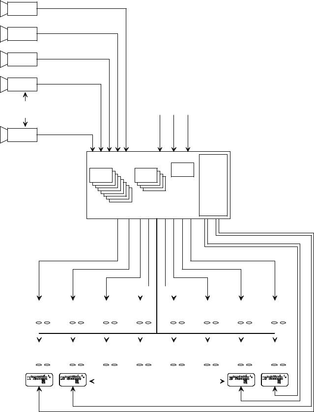
TC8800
Main Bay:
Up to 8 video input modules; 32 inputs per module. Up to 8 video output modules; 4 outputs per module. Subtotal: 256 inputs and 32 outputs on main bay.
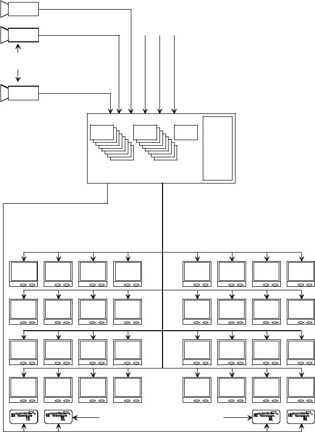
Monitor Expansion Bay:
Up to 8 video input modules (duplicating modules on main bay).
Up to 8 extra output modules (providing 4 additional outputs each).
Subtotal: 32 extra outputs added on to the main bay's outputs.
Total:
256 maximum inputs; 64 maximum outputs. Satellite configuration input capacity: 2304.
9

SUPPLEMENTARY SYSTEM COMPONENTS
The Allegiant accessory products provide many optional features to the base system. A brief description of accessory products is provided below. Complete specification information can be found in their respective product data sheets. All accessory products are designed to be compatible, where applicable, throughout the Allegiant series.
TC8550A System Keyboard
Full function system keyboard used for system control, programming, and pan/tilt/zoom operation. Includes integral pan/tilt joystick and zoom lens controls. Up to 8 keyboards are permitted on the TC8500 system. The TC8600 can accommodate up to 16. TC8800 systems can accommodate up to 32 keyboards. In TC8600 and TC8800 systems, keyboards above 8 are connected to the systems using TC8714A/TC8715A keyboard port expander accessory units described below.
TC8551A & TC8554
System Keyboards
These are function keyboards similar to the TC8550A except they contain four directional oriented, nonprotruding push buttons instead of a joystick for control over any pan/tilt equipped camera sites.
TC8553 & TC8555 System
Keyboards
These are function keyboards similar to the TC8550A except they contain a proportional joystick for controlling the variable speed pan/tilt functions of the AutoDome series of integral pan/tilt/zoom/camera domes. Rotation of the joystick also provides control over the lens's zoom functions.
TC8553-232 System Keyboard
The TC8553-232 is a full function keyboard similar to the TC8550A keyboard except it utilizes RS-232 protocol for data communication. It provides the capability of remotely locating an Allegiant keyboard over a conventional RS-232 transmission medium such as phoneline modems, fiber optics, etc. Requires a full duplex RS-232 link capable of operating at 9600 baud. All other specifications are the same as TC8553 keyboards. The TC8553-232 keyboards connect to the Allegiant’s main CPU bay via a TC8712A Series Console Port Expander. Up to four TC8553-232 keyboards may be connected to a single TC8712A Series unit. When used with dial-up type phoneline modems, the TC8553-232 keyboard provides a rudimentary dialing capability.
TC8557MK Keyboard Racking Kit
Rack mounting kit designed to provide vertical, horizontal or 30° inclined mounting for TC8550A, TC8551A, or TC8553 keyboards.
TC8557HL Keyboard
Extension Cable
Six conductor extension cable carries data/power for remote TC8550A, TC8551A, or TC8553 keyboards up to 30 meters (100 feet) away from main CPU bay.
TC8557HR Series Keyboard
Extension Kits
Interface kit used to remote TC8550A, TC8551A, or TC8553 keyboards up to 1.6 km (5000 feet) away from main CPU bay. Customer supplied 24 gage shielded-twisted pair (Belden 9841 or equivalent) required between main CPU bay site and keyboard site. Kit provides two junction boxes, interface cable, and appropriate keyboard power supply.
TC8568 Signal Distribution Unit
Main site control code distribution and line driver unit for communicating to Receiver/Drivers, Switcher Followers, and satellite systems. Provides 32 separate outputs for driving up to 256 remote devices. Either "star" or "daisy chain" wiring configurations may be used.
TC8768 Signal Distribution Unit
Same features and specifications as the TC8568 except that it contains twice the number of output connectors which provide 64 separate outputs for driving up to 512 remote devices.
TC8540C Series Alarm
Interface Units
Alarm gathering unit which accepts up to 64 dry contact closures or logic level inputs from remote sensing devices such as door contacts, PIRs, etc. and then reports the 'alarm' information to the main CPU bay. Alarm inputs may be configured in groups of 32 to accept either normally open or normally closed contacts. The TC8540C provides eight relay outputs which can be used to drive external alerting devices or VCRs.
TC8560, TC8561A,
TC8563, & TC8564A Series
Receiver/Driver Units
10
Decodes data transmitted from TC8568 unit for camera site control of Pan/Tilt, Zoom Lens, prepositions, and auxiliaries. Unit contains integral local test feature, auto-pan or random scanning, and is available in several input and output drive voltage versions.
TC700 Series AutoDomes™
Integral camera, high speed pan/tilt, zoom lens, and receiver/driver system in compact dome enclosure. Available in monochrome or color camera models. Various enclosure mounting options are available for indoor and outdoor applications.
TC8569-2, TC8569-4, TC8769-2,
TC8769-4 Series
Code Merger Unit
Control code merger and line driver unit used to combine control code from two systems (up to four with TC8569-4 version) for communicating to Receiver/Drivers, Switcher Followers, and satellite systems. Provides 32 separate outputs capable of driving up to 256 remote devices. Either "star" or "daisy chain" wiring configurations may be used. Unit will accept signal input either from Allegiant main CPU bay, TC8568 output, or an output from another TC8569-2, TC8569-4. Multiple units may be cascaded to obtain additional outputs.
TC8770 Switcher Follower Series,
TC8770SF, TC8770SG, TC8770LD,
TC8770LG Function Modules
Accessory unit which provides relay contact closures or LED driver outputs corresponding to cameras displayed on system monitors. The TC8770 may be configured to follow non-alarmed video, alarmed video, or both. TC8770 card cage holds any combination of up to 8 TC8770SF, TC8770SG, TC8770LD, or TC8770LG modules. Each TC8770SF or TC8770SG type module contains 16 relay contact outputs. A single TC8770LD or TC8770LG type module drives up to 64 low current type LEDs.
TC8770I Interconnect Panel
Accessory for the TC8770 Switcher Follower which provides convenient screw terminal interface for external connections. Mates to ribbon cables supplied with TC8770SF or TC8770LD function modules.
TC8712A Series Console
Port Expander Units
The TC8712A port expander interfaces to the RS232 CONSOLE port of an Allegiant system to permit up to 4 external PCs or other computing devices to be connected to the system. This permits multiple PCs or computing devices to communicate with a single Allegiant system.
TC8713A Series Alarm
Port Expander Units
The TC8713A interfaces to either a TC8600 or a TC8800 system’s RS-232 ALARM port to permit additional TC8540C alarm interface units to be connected to the system. In a TC8600 system, 2 TC8540C units can be connected to the TC8713A. In TC8800 systems, up to 4 TC8540C units can be connected to the TC8713A.
TC8714A, TC8715A Series
Keyboard Port Expander Units
The TC8714A keyboard port expander interfaces to the COMM PORT 2 of either a TC8600 or a TC8800 system to permit additional keyboards to be connected to the system. Any combination of up to 8 TC8550A, TC8551A or TC8553 keyboards can be connected to the system using one TC8714A unit. In TC8800 systems, typically 3 TC8714A units, each having 8 keyboards, can be interfaced to the system using a single TC8715A unit. This would provide a quantity of 24 "port expanded" keyboards in a TC8800 system for a total of 32 system keyboards. Alternatively all 32 keyboards can be connected using 4 TC8714As and a single TC8715A.
11
TC8780 Series Data Converter Units
The TC8780 Series convert the biphase control code generated by Allegiant series matrix switchers and the TC8135 Series controller/followers into standard RS-232, and converts RS-232 back to biphase code. This provides the capability of transmitting the biphase control code over conventional RS-232 transmission media (phone modems, fiber optics, microwaves, etc.) The TC8780 can also be used to perform the Satellite Selector functions in Allegiant satellite system configurations and operate as a 15channel remote signal distribution unit.
TC8781 Series Time/Data
Converters
The TC8781 Series are accessory units that decode the Allegiant system’s encoded time/date information generated on the biphase control code line and convert it into an RS-422 format using the GPS format. This time/date information can be used to interface into external time/date inserter products (such as the Kalatel KTS-53-16), which are designed to be synchronized via a GPS signal. The electrical and mechanical specifications are the same as the TC8780 Series units.
TC8785 Series Code Converters
TC8785 Series units are designed for use in existing Allegiant systems which have been upgraded to operate the new AutoDome series of cameras. The TC8785 Code Converters are used to provide the source for the “fixed speed” control code when the system is generating the new “variable speed” control code preferred by the AutoDome cameras. The TC8785 Series Code Converter receives the “variable speed” control code from the Allegiant via its TC8568 Signal Distribution unit and converts it into the appropriate “fixed speed” control code. Outputs from the TC8785 Series Code Converter may be connected to older TC8561 Series receiver/drivers using existing field cables.
Code Translator Units
Code translators are available which can convert Allegiant control code to and from other manufacturer code formats. Contact your Bosch local manufacturer’s representative for additional information.
TC8808 Video Interconnect Panel
Optional accessory item which provides TC8600 and TC8800 systems with the capability of looping up to 32 video inputs per panel. This 'patch' panel contains 32 BNC connectors on its front for external video connections and two 16-contact ribbon connectors on its rear. Two 16-conductor ribbon cables are included for interfacing the patch panel to the video looping connectors on the TC8600, TC8800 equipment bays. The patch panel is one standard EIA 19-inch rack unit high and one unit wide.
TC8579SE Service Extender Card
Service extender card used for troubleshooting TC8500 system CPU, video input, and video output modules
12
TC8779SE Service Extender Card
Service extender card used for troubleshooting TC8600 and TC8800 CPU and video output modules and all TC8700 modules.
TC8820SE Service Extender Card
Service extender card used for troubleshooting TC8600 and TC8800 system video input modules.
TC8x59 Series Allegiant
Master Control Software
The TC8x59 Series Allegiant Master Control Software consists of an IBM® or IBM compatible program which allows quick and easy configuration of standard system features. An appropriate Allegiant Master Control Software package exists for each type of Allegiant system, i.e., the TC8559 is used for TC8500 Series systems, the TC8659 is used for TC8600 Series systems, etc. The program provides advanced alarm and sequence programming in addition to other features which are not available using the system keyboard. An on-line real-time monitoring of system status and a keyboard emulation mode is also included.
Other standard Master Control Software features include: user passwords, lockout tables, 64 programmable time event functions, custom alarm responses using the VersAlarmTM alarm mode, and a keyboard emulation mode. In addition to the operational switching sequences normally inputted from the standard keyboard, much more complex switching sequences may be programmed which incorporate remote control commands as part of the switching sequence. The ability to detect video loss in TC8600 Series and TC8800 Series systems and to monitor the system operation in real-time on all systems is a standard feature of the Allegiant Master Control Software package.
The TC8x59 Software package includes a 3 1/2-inch program disk containing Allegiant Master Control
Software program, interface cable, and Users Manual for custom programming of Allegiant system.
A special version, the TC8059, includes multiple disks for programming TC8500 Series, TC8600 Series, and TC8800 Series Allegiant systems. The TC8059 software package is intended to be used for programming a mix of Allegiant systems operating in a Satellite configuration.
The master control software program requires an IBM PC or true IBM compatible PC with at least 640 k bytes of memory, DOS 3.0 or higher, one serial port, one parallel port, and MDA, Hercules™, CGA, EGA, or VGA display (or compatible).
Windows Based Allegiant Software
The TC8850 is a software package utilizing a Graphical User Interface (GUI) to integrate and control security systems. The GUI interfaces directly to the Allegiant system and provides complete control and programming of all system features. The GUI software program requires an 486DX2-66 MHz PC or better running Windows 95 or Windows NT with at least 16Mbytes of memory, one serial port, one parallel port, 3.5” floppy disk drive, mouse or trackball, and SVGA display. Refer to the TC8850 data sheet for complete specifications.
_________________
Windows is a registered trademark of Microsoft Corporation. IBM is a registered trademark of IBM Corporation.
Hercules is a trademark of Hercules Technology.
Logging Printer
An optional RS-232 serial printer may be connected to the main CPU bay to provide a permanent record of significant changes in the system's status. Time and date is printed for system events such as alarms, start-ups after power failures, sequence loadings, operators logging-on/off to keyboards, and downloading of information from the optional Master Control Software package. The printer may also be used to obtain hard copies of all system Tables and Sequences.
13
|
Up To 64 Video |
|
|
Additional |
Inputs Maximum |
|
|
|
|
|
|
System Cameras |
|
|
|
|
|
TC8511A |
|
TC8521VIM |
|
CPU |
TC8505PS |
TC8532VOM |
Module |
||
8 x 8 CH |
4 x 2 CH |
|
Power |
Input Cards |
Output Cards |
|
|
|
|
Supply |
|
|
|
|
|
|
|
|
Module |
TC8501B SERIES MAIN CPU BAY
3 m (10 ft) Interconnect Cable Supplied With Keyboard
Up to 8 Monitor Outputs
Video Coax
|
|
|
|
|
|
|
|
|
|
|
|
|
|
|
|
|
|
|
|
|
|
|
|
|
|
|
|
|
|
|
|
|
|
|
|
|
|
|
|
|
|
|
|
|
Monitor 1 |
|
|
|
|
|
Monitor 2 |
|
|
|
Monitor 3 |
|
|
|
Monitor 4 |
|
|
|
Monitor 5 |
|
|
|
Monitor 6 |
|
|
|
|
Monitor 7 |
|
|
|
Monitor 8 |
|
||||||||
|
|
|
|
|
|
|
|
|
|
|
|
|
|
|
|
|
|
|
|
|
|
|
|
|
|
|
|
|
|
|
|
|
|
|
|
|
|
|
|
|
|
|
|
|
|
|
|
|
|
|
|
|
|
|
|
|
|
|
|
|
|
|
|
|
|
|
|
|
|
|
|
|
|
|
|
|
|
|
|
|
|
|
|
|
|
|
|
|
|
|
|
|
|
|
|
|
|
|
|
|
|
|
|
|
|
|
|
|
|
|
|
|
|
|
|
|
|
|
|
|
|
|
|
|
|
|
|
|
|
|
|
|
|
|
|
|
|
|
|
|
|
|
|
|
|
|
|
|
|
|
|
|
|
|
|
|
|
|
|
|
|
|
|
|
|
|
|
|
|
|
|
|
|
|
|
|
|
|
|
|
|
|
|
|
|
|
|
|
|
|
|
|
|
|
|
|
|
|
|
|
|
|
|
|
|
|
|
|
|
|
|
|
|
|
|
|
|
|
|
|
|
|
|
|
|
|
|
|
|
|
|
|
|
|
|
|
|
|
|
|
|
|
|
|
|
|
|
|
|
|
|
|
|
|
|
|
|
|
|
|
|
|
|
|
|
|
|
|
|
|
|
|
|
|
|
|
|
|
|
|
|
|
|
|
|
|
|
|
|
|
|
|
|
|
|
|
|
|
|
|
Maximum of 8 TC8550A, TC8551A, or TC8553
Full Function Keyboards Up to 1.5 km (5000 ft)
Away Using Optional Remote Hookup Kit
S9506028AE
TC8500 Video Switching System
14
|
|
Up To 128 |
|
|
Additional |
Video Inputs Maximum |
|||
System Cameras |
|
|
|
|
|
|
TC8610A |
|
|
TC8621 |
TC8834 |
CPU |
|
|
Module |
TC8605 |
|||
8 x 16 CH |
4 x 4 CH |
|||
|
Power |
|||
Input Cards |
Output Cards |
|
||
|
Supply |
|||
|
|
|
||
|
|
|
Module |
|
|
TC8601 Series Main CPU Bay |
|
||
Up to 16 Monitor Outputs
3 m (10 ft) Interconnect Cable Supplied With Keyboard
Video Coax
|
|
|
|
|
|
|
|
|
|
|
|
|
|
|
|
|
|
|
|
|
|
|
|
|
|
|
|
|
|
|
|
|
|
|
Monitor 1 |
|
|
|
Monitor 2 |
|
|
|
Monitor 3 |
|
|
|
Monitor 4 |
|
|
|
Monitor 5 |
|
|
|
Monitor 6 |
|
|
Monitor 7 |
|
|
|
Monitor 8 |
|
||||
|
|
|
|
|
|
|
|
|
|
|
|
|
|
|
|
|
|
|
|
|
|
|
|
|
|
|
|
|
|
|
|
|
|
|
|
|
|
|
|
|
|
|
|
|
|
|
|
|
|
|
|
|
|
|
|
|
|
|
|
|
|
|
|
|
|
|
|
|
|
|
|
|
|
|
|
|
|
|
|
|
|
|
|
|
|
|
|
|
|
|
|
|
|
|
|
|
|
|
|
|
|
|
|
|
|
|
|
|
|
|
|
|
|
|
|
|
|
|
|
|
|
|
|
|
|
|
|
|
|
|
|
|
|
|
|
|
|
|
|
|
|
|
|
|
|
|
|
|
|
|
|
|
|
|
Monitor 9 |
|
|
|
|
Monitor 10 |
|
|
|
|
Monitor 11 |
|
|
|
Monitor 12 |
|
|
|
Monitor 13 |
|
|
|
Monitor 14 |
|
|
|
|
Monitor 15 |
|
|
|
Montior 16 |
|
||||||||||||||||
|
|
|
|
|
|
|
|
|
|
|
|
|
|
|
|
|
|
|
|
|
|
|
|
|
|
|
|
|
|
|
|
|
|
|
|
|
|
|
|
|
|
|
|
|
|
|
|
|
|
|
|
|
|
|
|
|
|
|
|
|
|
|
|
|
|
|
|
|
|
|
|
|
|
|
|
|
|
|
|
|
|
|
|
|
|
|
|
|
|
|
|
|
|
|
|
|
|
|
|
|
|
|
|
|
|
|
|
|
|
|
|
|
|
|
|
|
|
|
|
|
|
|
|
|
|
|
|
|
|
|
|
|
|
|
|
|
|
|
|
|
|
|
|
|
|
|
|
|
|
|
|
|
|
|
|
|
|
|
|
|
|
|
|
|
|
|
|
|
|
|
|
|
|
|
|
|
|
|
|
|
|
|
|
|
|
|
|
|
|
|
|
|
|
|
|
|
|
|
|
|
|
|
|
|
|
|
|
|
|
|
|
|
|
|
|
|
|
|
|
|
|
|
|
|
|
|
|
|
|
|
|
|
|
|
|
|
|
|
|
|
|
|
|
|
|
|
|
|
|
|
|
|
|
|
|
|
|
|
|
|
|
|
|
|
|
|
|
|
|
|
|
|
|
|
|
|
|
|
|
|
|
|
|
|
|
|
|
|
|
|
|
|
|
|
|
|
|
|
|
|
|
|
|
|
|
|
|
|
|
|
|
|
|
|
|
|
|
|
|
|
|
|
|
|
|
|
|
|
|
|
|
|
|
|
|
|
|
|
|
|
|
|
|
|
|
|
|
|
|
|
|
|
|
|
|
|
Maximum of 16 TC8550A, TC8551A, or TC8553
Full Function Keyboards Up to 1.5 km (5000 ft)
Away Using Optional Remote Hookup Kit
S9506029AE
TC8600 Series Video Switching System
15
|
Up To 256 |
|
|
Video Inputs |
|
|
Maximum |
|
Additional |
|
|
System Cameras |
|
|
TC8821 |
TC8834 |
TC8810A |
8 x 32 CH |
8 x 4 CH |
CPU |
Input Cards |
Output Cards |
Module |
|
|
TC8805 |
|
|
Power |
|
|
Supply |
|
|
Module |
|
TC8801 Series Main CPU Bay |
|
Up to 32 Monitor Outputs |
|
|
3 m (10 ft) Interconnect |
|
|
|
|
|
|
Cable Supplied With Keyboard |
|
|
|
|
Multiple Video Coax |
|
|
Monitor 1 |
Monitor 2 |
Monitor 3 |
Monitor 4 |
Monitor 17 |
Monitor 18 |
Monitor 5 |
Monitor 6 |
Monitor 7 |
Monitor 8 |
Monitor 21 |
Monitor 22 |
Monitor 9 |
Monitor 10 |
Monitor 11 |
Monitor 12 |
Monitor 25 |
Monitor 26 |
Monitor 13 |
Monitor 14 |
Monitor 15 |
Monitor 16 |
Monitor 29 |
Monitor 30 |
|
|
|
Maximum of 32 TC8550A, TC8551A, or TC8553 |
|
|
|
|
|
Full Function Keyboards Up to 1.5 km (5000 ft) |
|
|
|
|
|
Away Using Optional Remote Hookup Kit |
|
|
Monitor 19
Monitor 23
Monitor 27
Monitor 31
Monitor 20
Monitor 24
Monitor 28
Monitor 32
S9506030AE
TC8800 Series Single Bay System (256 by 32 Configuration)
16

Up To 256 Video
Inputs Maximum
TC8821 |
TC8834 |
TC8810A |
8 x 32 CH |
8 x 4 CH |
CPU |
Input Cards |
Output Cards |
Module |
|
|
TC8805 |
|
|
Power |
|
|
Supply |
|
|
Module |
|
|
Control |
|
|
Data |
Coax Ribbon |
|
|
Jumper Cables |
|
|
(Supplied) |
|
|
TC8821 |
TC8834 |
TC8816A |
Data |
||
8 x 32 CH |
8 x 4 CH |
Receiver |
Input Cards |
Output Cards |
Module |
|
|
TC8805 |
|
|
Power |
|
|
Supply |
|
|
Module |
Monitor 1
Monitor 5
Monitor 9
Monitor 13
Monitor 17
Monitor 21
Monitor 25
Monitor 29
Monitor 2
Monitor 6
Monitor 10
Monitor 14
Monitor 18
Monitor 22
Monitor 26
Monitor 30
Monitor 3
Monitor 7
Monitor 11
Monitor 15
Monitor 19
Monitor 23
Monitor 27
Monitor 31
Monitor 4
Monitor 8
Monitor 12
Monitor 16
Monitor 20
Monitor 24
Monitor 28
Monitor 32
Monitor 33
Monitor 37
Monitor 41
Monitor 45
Monitor 49
Monitor 53
Monitor 57
Monitor 61
Monitor 34
Monitor 38
Monitor 42
Monitor 46
Monitor 50
Monitor 54
Monitor 58
Monitor 62
Maximum of 32 TC8550A, TC8551A, or TC8553 Full Function Keyboards Up to 1.5 km (5000 ft)
Away Using Optional Remote Hookup Kit
Monitor 35
Monitor 39
Monitor 43
Monitor 47
Monitor 51
Monitor 55
Monitor 59
Monitor 63
Monitor 36
Monitor 40
Monitor 44
Monitor 48
Monitor 52
Monitor 56
Monitor 60
Monitor 64
S9506031AE
TC8800 Series Dual Bay System
(256 by 64 Configuration)
17
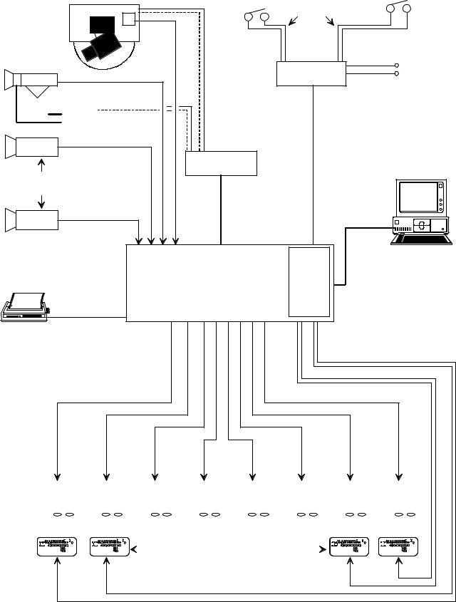
Typical
AutoDome™
Camera Video
Coax
|
|
|
|
Video Coax |
Pan/ |
|
|
|
|
|
TC8561A |
|
|
|
Tilt |
|
|
|
|
|
Receiver/ |
Up to 64 Receiver/ |
||
|
|
|||
|
|
Driver |
||
|
|
Driver Units |
||
|
|
|
|
|
|
|
|
|
|
Video Coax
Additional
System Cameras
Up to 64
Video Inputs
Maximum
Video Coax
64 Separate
Alarm Inputs
Twisted-Pair |
Contact Closure |
|
Typical |
||
or Active Low Logic Level |
||
|
TC8540C Alarm
Interface Unit
Up to 1.5 km (5000 ft) Using 18 g Shielded Twisted Pair Cable
(Belden 8760 or Equivalent)
32 Separate Outputs
TC8568 Signal
Distribution Unit
2 m (6 ft) Interconnect Cable Supplied With TC8568 Providing Data and Power Connections
2 m (6 ft) Interconnect Cable Supplied With TC8540C Providing Data and Power Connections
Optional TC8559 Master Control Software or Graphical Users Interface (GUI) Software package Can
Be Run on IBM or IBM Compatible
RS-232 Data
|
|
|
|
|
|
|
|
|
|
|
|
|
|
|
|
|
|
|
|
|
|
|
|
TC8511A |
|
|
TC8521VIM |
|
|
|
|
|
|
|
|
|
TC8532VOM |
|
|
|
|
CPU |
|
||||||||
|
|
|
|
|
|
|
|
|
|
|
|
|
|
Module |
TC8505PS |
||||||||||
|
|
8 x 8 CH |
|
|
|
|
|
|
|
|
|
|
4 x 2 CH |
|
|
|
|
|
Power Supply |
||||||
|
Input Cards |
|
|
|
|
|
|
|
|
|
Output Cards |
|
|
|
|
|
Module |
||||||||
|
|
|
|
|
|
|
|
|
|
|
|
|
|
|
|
|
|
|
|
|
|
|
|
|
|
|
|
|
|
|
|
|
|
|
|
|
|
|
|
|
|
|
|
|
|
|
|
|
|
|
|
|
|
|
|
|
|
|
|
|
|
|
|
|
|
|
|
|
|
|
|
|
|
|
|
|
|
|
|
|
|
|
|
|
|
|
|
|
|
|
|
|
|
|
|
|
|
|
|
|
|
|
|
|
|
|
|
|
|
|
|
|
|
|
|
|
|
|
|
|
|
|
|
|
|
|
|
|
|
|
|
|
|
|
|
|
|
|
|
|
|
|
|
|
|
|
|
|
|
|
|
|
|
|
|
|
|
|
|
|
|
|
|
|
|
|
|
|
|
|
|
|
|
|
|
|
|
|
|
|
|
RS-232 Data
TC8501B Series Main CPU Bay
3 m (10 ft) Interface Cable Provided With TC8500 Series Main CPU Bay
Up to 8 Monitor Outputs
3 m (10 ft) Interconnect Cable Supplied With Keyboard
Video Coax
|
|
|
|
|
|
|
|
|
|
|
|
|
|
|
|
|
|
|
|
|
|
|
|
|
|
|
|
|
|
|
|
|
|
|
|
|
|
|
|
|
|
|
|
|
|
|
|
Monitor 1 |
|
|
|
|
|
Monitor 2 |
|
|
|
|
Monitor 3 |
|
|
|
Monitor 4 |
|
|
|
Monitor 5 |
|
|
|
Monitor 6 |
|
|
Monitor 7 |
|
|
|
Monitor 8 |
|
||||||||
|
|
|
|
|
|
|
|
|
|
|
|
|
|
|
|
|
|
|
|
|
|
|
|
|
|
|
|
|
|
|
|
|
|
|
|
|
|
|
|
|
|
|
|
|
|
|
|
|
|
|
|
|
|
|
|
|
|
|
|
|
|
|
|
|
|
|
|
|
|
|
|
|
|
|
|
|
|
|
|
|
|
|
|
|
|
|
|
|
|
|
|
|
|
|
|
|
|
|
|
|
|
|
|
|
|
|
|
|
|
|
|
|
|
|
|
|
|
|
|
|
|
|
|
|
|
|
|
|
|
|
|
|
|
|
|
|
|
|
|
|
|
|
|
|
|
|
|
|
|
|
|
|
|
|
|
|
|
|
|
|
|
|
|
|
|
|
|
|
|
|
|
|
|
|
|
|
|
|
|
|
|
|
|
|
|
|
|
|
|
|
|
|
|
|
|
|
|
|
|
|
|
|
|
|
|
|
|
|
|
|
|
|
|
|
|
|
|
|
|
|
|
|
|
|
|
|
|
|
|
|
|
|
|
|
|
|
|
|
|
|
|
|
|
|
|
|
|
|
|
|
|
|
|
|
|
|
|
|
|
|
|
|
|
|
|
|
|
|
|
|
|
|
|
|
|
|
|
|
|
|
|
|
|
|
|
|
|
|
|
|
|
|
|
|
|
|
|
|
|
|
|
|
|
|
|
|
|
Maximum of 8 TC8550A, TC8551A, or TC8553
Full Function Keyboards Up to 1.5 km (5000 ft)
Away Using Optional Remote Hookup Kit
S9506032AE
TC8500 Full Capacity Configuration
18
Typical |
|
|
AutoDome™ |
|
Video |
Camera |
|
|
|
Coax |
|
|
|
|
|
|
Pan/ |
|
|
|
|
|
|
|
|
|
|
|
|
|
TC8561A |
|
|
|
|
|||
|
|
Tilt |
|
|
|
|
|
|
|
||
|
|
|
|
Receiver/ |
Up to 256 |
|
|
||||
|
|
|
|
|
|
|
|
|
|||
|
|
|
|
|
|
|
Driver |
Receiver/ |
|
|
|
|
|
|
|
|
|
|
|
|
Driver Units |
|
|
|
|
|
|
|
|
|
|
|
|
|
|
|
|
|
|
|
|
|
|
|
|
|
|
|
|
|
|
|
|
|
|
|
Video Coax |
|
|
|
|
|
|
|
|
|
|
|
|
||
|
|
|
|
|
|
|
|
|
|
|
|
|
Additional |
|
|
|
|
|
|||||
System Cameras |
|
|
256 Camera |
|
|
||||||
|
|
|
|
|
|
|
|
|
Inputs Total |
|
|
|
|
|
|
|
|
|
|
|
|
|
|
|
|
|
|
|
|
|
|
|
|
|
|
|
|
|
|
|
|
|
|
|
|
|
|
|
|
|
|
|
|
|
|
|
|
|
|
|
|
|
|
|
|
|
|
|
Video Coax |
|
|
|
|
|
|
|
|
|
|
|
|
|
|
Up to 64 Alarm
Inputs to Each
TC8540C Unit
|
|
|
8 Pairs |
|
|
|
of Relay |
Up to 1.5 km (5000 ft) |
|
Contact Closure |
Outputs |
|
|
||
Using 18 g Shielded |
|
or Logic Level |
|
Twisted Pair |
|
Inputs |
|
Cable (Belden |
|
|
|
8760 or Equiv.) |
|
|
|
Twisted |
TC8540C Alarm |
|
TC8540C Alarm |
Interface Unit |
|
Interface Unit |
|
Pair |
|
|
|
Typical |
|
|
|
TC8540C Alarm |
|
TC8540C Alarm |
12 |
Interface Unit |
|
Interface Unit |
VDC |
Control |
|
|
|
Code Line |
|
|
|
|
|
TC8713A Alarm Port |
|
32 Separate |
|
Expander Accessory |
|
Outputs |
|
|
|
TC8568 Signal |
|
|
Optional TC8859 Master |
Distribution Unit |
|
|
|
|
|
Control Software or |
|
|
|
|
|
|
|
|
Graphical Users Interface |
|
|
|
(GUI) Software Package Can |
|
|
|
Be Run on IBM or IBM |
|
Up to 256 |
|
Compatible Computer |
|
|
|
|
TC8808 |
Alarm Inputs |
|
|
Maximum |
|
|
|
Interconnect Panel |
|
|
RS-232 Data
Serial Logging
Printer Capability
TC8714A / TC8715A Port
Expander Accessories
Keyboard Expander
Units Used For System
Keyboards Above 16
|
|
|
|
|
System |
|
Monitor |
|
Monitors |
||
|
1 |
|
|
|
1 to 32 |
|
|
|
|
|
|
|
|
|
|
|
|
|
|
|
|
|
|
|
|
|
|
|
|
|
|
|
|
|
|
|
|
|
|
|
|
|
|
|
|
|
|
|
|
|
|
|
|
|
|
|
|
|
|
|
|
|
|
|
|
|
|
|
|
|
TC8810A |
|
|
|
|
|
|
|
|
|
|
|
|
|
|
|
|
|
|
|
|
|
|
|
|
|
|
|
|
|
|
|
|
|
|
|
|
|
|
|
|
|
|
|
|
|
|
CPU |
|
|
|
|
|
|
|
|
|
|
|
|
Up to 8 TC8821 |
|
|
|
|
|
|
|
|
Up to 8 TC8834 |
|
|
|
|
|
|
|
Module |
TC8805 |
RS-232 Data |
|
|
|
|
|
|
|
|
||||||||||||||||||
|
|
32 Channel |
|
|
|
|
|
|
|
|
|
4 Channel |
|
|
|
|
|
|
|
|
Power |
|
|
|
|
|
|
|
|
|||||||||||||||||
|
|
|
|
|
|
|
|
|
|
|
|
|
|
|
|
|||||||||||||||||||||||||||||||
|
Input Cards |
|
|
|
|
|
|
|
|
Output Cards |
|
|
|
|
|
|
|
|
|
|
|
|
|
|
|
|
|
|
||||||||||||||||||
|
|
|
|
|
|
|
|
|
|
|
|
|
|
|
|
|
|
|
|
|
|
|
|
|
|
|
|
|
|
|
|
|
|
|
|
Supply |
|
|
|
|
|
|
|
|
|
|
|
|
|
|
|
|
|
|
|
|
|
|
|
|
|
|
|
|
|
|
|
|
|
|
|
|
|
|
|
|
|
|
|
|
|
|
Module |
|
|
|
|
|
|
|
|
|
|
|
|
|
|
|
|
|
|
|
|
|
|
|
|
|
|
|
|
|
|
|
|
|
|
|
|
|
|
|
|
|
|
|
|
|
|
|
|
|
|
|
|
|
|
|
|
|
|
|
|
|
|
|
|
|
|
|
|
|
|
|
|
|
|
|
|
|
|
|
|
|
|
|
|
|
|
|
|
|
|
|
|
|
|
|
|
|
|
|
|
|
|
|
|
|
|
|
|
|
|
|
|
|
|
|
|
|
|
|
|
|
|
|
|
|
|
|
|
|
|
|
|
|
|
|
|
|
|
|
|
|
|
|
|
|
|
|
|
|
|
|
TC8801 SERIES MAIN CPU BAY |
|
|
|
||
Video Ribbon |
|
|
|
|
Main Bay Can |
Jumper Cables |
|
|
|
|
|
Supplied With TC8802 |
|
|
|
|
Operate Up |
|
|
|
|
|
to 8 Keyboards |
|
|
TC8816 |
|
|
|
Up to 8 TC8821 |
Up to 8 TC8834 |
Data Receiver |
|
|
|
Module |
TC8805 |
|
|
||
32 Channel |
4 Channel |
|
|
|
|
Input Cards |
Output Cards |
|
Power |
|
|
|
|
|
Supply |
3 m (10 ft) Interconnect |
|
|
|
|
Module |
||
|
|
|
Cable Supplied With Keyboard |
||
|
|
|
|
||
TC8802 SERIES MONITOR EXPANSION BAY |
|
|
|
||
|
Monitor |
|
|
|
|
|
Expansion |
|
|
|
|
|
Bay Can |
|
|
|
|
|
Operate Up |
|
|
|
|
|
to 8 Keyboards |
|
|
|
|
Monitor |
|
|
Monitor |
System |
Monitor |
|
|
Monitors |
|||
32 |
|
|
33 |
64 |
|
|
|
33 to 64 |
|||
|
|
|
|
|
|
Maximum of 32 TC8550A, TC8551A, or TC8553 |
|
|
|
||
Full Function Keyboards Up to 1.5 km (5000 ft) |
|
|
|
||
Away Using Optional Remote Hookup Kit |
|
|
|
||
|
|
|
|
|
S9506033AE |
TC8800 Full Capacity Configuration
19

INSTALLATION PROCEDURE
CAUTION: Do Not Apply power to equipment until instructed to do so.
Main CPU Bay Installation
Before discarding the shipping cartons, verify that the various pieces of equipment have no evidence of carrier damage.
Remove the front panel of the main CPU bay (TC8x01) and the front panels of any supplied expansion bay (TC8802) by loosening the 4 corner fasteners.
Install power supply (TC8x05) in far right position of the TC8x01 main CPU bay insuring proper alignment and seating of the module into the rear mating connector. Verify power supply ON/OFF switch is in the OFF position. Repeat procedure for any supplied TC8802 monitor expansion bay.
Install 4 supplied screws and star washers on the rear panel of the bay(s) surrounding the power supply line cord. This fastens the power supply securely in place.
CAUTION: IF THE ALLEGIANT CARD CAGE IS TO BE TRANSPORTED, THE MAIN POWER SUPPLY SHOULD BE REMOVED TO PREVENT POSSIBLE DAMAGE TO THE BAY’S INTERNAL PARTS.
If the bay(s) are to be installed into a standard 19inch EIA rack, remove the 4 rubber bumper foot pads found on the bottom of the bay before trying to install it. Four holes are provided for mounting the bay(s) in the rack. If any TC8802 expansion bays is supplied, it should be located as close as possible to the TC8801 main CPU bay to facilitate cable interconnections.
The TC8601, TC8801, and TC8802 bays should be installed such that there is at least 9 cm (3.5 inches) of clearance above and below the bay.
This is necessary to allow for proper cooling of the system. Failure to provide proper clearance may cause the equipment to exceed its recommended operating temperature range.
NOTE: A TC8802 BAY SHOULD BE LOCATED CLOSE ENOUGH TO THE TC8801 SO THAT THE SUPPLIED 2 METER (6 FOOT) DATA INTERCONNECT CABLE (TO BE ATTACHED LATER) CAN BE USED.
Video Input Modules
For TC8600 and TC8800 systems, termination switches on the Video Input Modules (VIM) must be set to the correct position prior to installation. Read the termination instructions (section Camera and Monitor Connections, subsection Termination) prior to actually installing the Video Input Modules on these systems.
The appropriate number of Video Input Modules (TC8x21 or TC8521VIM) should be installed in the TC8x01 main bay starting with the left most slot. If the TC8802 Monitor Expansion Bay is being used, it should receive the same number of Video Input Modules as the main bay. If less than full capacity is being used, the modules should be inserted in a left- to-right manner so that the lower camera numbers are used up first.
Typical Video Input Module Insertion
To insure full crosspoint capability, it is important that if the TC8802 is being used, both the TC8801 Main Bay and TC8802 Monitor Expansion Bay must be loaded up with the same number of modules (each bay receives half of the modules). The Video Input Modules are identical and are interchangeable within the designated VIM slots without having to make any changes to the module.
20
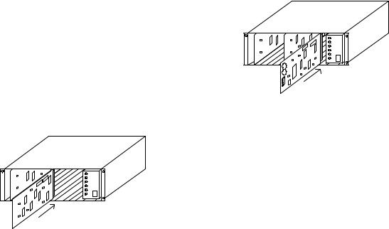
Video Output Modules
The next set of slots can contain up to 4 (8 on the TC8800) Video Output Modules (TC8834 or TC8532VOM). If counting from left to right, these are slots 9 to 12 for the TC8500 and TC8600, and 9 to 16 for the TC8800. Install the appropriate number of modules (starting at the left) into these slots. If fewer than the maximum number of Video Input Modules are installed, there will be empty slots between the Input and the Output Modules; make sure that the Output Modules are inserted into the correct slots.
Typical Video Output Module Insertion
If the TC8802 Monitor Expansion Bay is being used, it should be loaded with Video Output Modules in the same fashion. The Main CPU Bay should be FULLY loaded with 8 Output Modules before putting Output Modules into the Monitor Expansion Bay. Remaining Output Modules are inserted into the Monitor Expansion Bay starting at slot 9 on a TC8802. If fewer than the maximum number of outputs are being used, the Monitor Expansion Bay may contain fewer Output Modules than the Main CPU Bay.
All Video Output Modules are identical and are interchangeable within the designated VOM slots.
CPU Module
The next slot over in the TC8x01 Main Bay will contain the system CPU module. This should be the right most slot adjacent to the power supply.
NOTE: THE CPU MODULE CONTAINS TWO LITHIUM BATTERIES MOUNTED ON THE COMPONENT SIDE OF THE PRINTED CIRCUIT BOARD. A RED RECTANGULAR INSULATING TAG MAY BE INSTALLED IN BETWEEN THE TOP OF THE BATTERIES AND THE BATTERY HOLDER CLIP. THIS TAG PREVENTS BATTERY DRAINAGE DURING STOCKING. REMOVE TAG IF SO EQUIPPED.
Typical CPU Module Insertion
If a TC8802 Monitor Expansion is supplied, it will contain a TC8816A Data Receiving Module in this slot. Install the appropriate CPU or Data Receiver Module at this time.
IMPORTANT: Verify that the settings of the two 8 position DIP switches located on the front edge of the CPU Module and the Data Receiver Module are set according to the table below.
Bay Type |
Module |
DIP Setting |
TC8501C |
TC8511C CPU |
S1001, All OFF, |
|
|
S1002 switch 7 ON, |
|
|
All others OFF |
TC8x01A |
TC8x10A CPU |
S100, All OFF, |
|
|
S101 switch 7 ON, |
|
|
All others OFF |
TC8802A |
TC8816A |
S101 switch 3 and 7 |
|
Data Receiver |
ON, All others OFF |
Camera and Monitor Connections
Refer to the rear panel diagrams on the following pages for the following steps.
For All Systems
Connect system cameras to the appropriate video inputs, but as a minimum connect one known operating camera to video input #1 on the rear of the TC8x01 main CPU bay. Use only those inputs that correspond to an installed Video Input Module (VIM). Special instructions concerning TC8600 or TC8800 systems, termination, and expansion bays are given in the sections below. Also connect desired monitors to the rear of the TC8x01 bay, making sure to at least connect a monitor to video output #1. The video outputs are the left most column of BNC connectors on the rear of the bay. Use only those outputs that correspond to an installed Video Output Module (VOM).
21
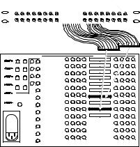
TC8600 and TC8800 Video Inputs
The TC8601 and TC8801 main bays have only 96 direct BNC connectors available for video input. Cameras above 96 require the use of the TC8808 Video Interconnect ("Patch") Panel. Each patch panel provides 32 additional BNCs for video input. Patch panels are connected to the rear of the main bay using the supplied ribbon cables. Each cable can carry video for up to 16 cameras. Two cables can be attached to each patch panel to support up to 32 cameras per panel. Each ribbon cable should be attached to the appropriate "VIDEO" connector on the rear of the main bay. The ribbon cable connectors contain a small “key” protrusion formed into one side of the connector to assure proper placement into the mating connectors. Be careful not to force the cables into the mating connectors backwards. For example, the two ribbon cables from the first patch panel (supporting the thirty-two cameras 97 through 128) should be attached to the main bay connectors labeled "VIDEO 97-112" and "VIDEO 113-128." Extra connectors are provided on the main bay for "looping" purposes. If camera inputs are not being looped to other equipment, only one connector for each range of cameras (e.g., "VIDEO 97-112") needs to be connected.
The TC8600 system is supplied with one TC8808 (patch panel plus two TC8809 ribbon cables). This should be installed on the rear of the racking equipment to permit immediate or future connections of camera inputs 97 through 128.
Camera Input 97
Camera Input 98 
16 |
15 |
14 |
13 |
12 |
11 |
10 |
9 |
8 |
7 |
6 |
5 |
4 |
3 |
2 |
1 |
32 |
31 |
30 |
29 |
28 |
27 |
26 |
25 |
24 |
23 |
22 |
21 |
20 |
19 |
18 |
17 |
TC8808 Interconnect Panel |
|
|
|
|
|
|
|
Upper TC8809 Cable |
|||||||
Lower TC8809 Cable
|
KEYBOARD |
|
VIDEO |
|
|
|
|
VIDEO IN |
|
|
|
|
|
CONSOLE |
|
OUT |
|
|
|
|
|
|
|
|
|||
|
|
|
|
|
8 |
7 |
6 |
5 |
LOOP 1-16 |
4 |
3 |
2 |
1 |
ALARM |
1 |
2 |
13 |
1 |
|
|
|
|
|
|
|
|
|
|
|
|
|
|
|
|
|
|
|
|
|
|
|
|
|
|
|
|
16 |
15 |
14 |
13 |
LOOP 17-32 |
12 |
11 |
10 |
9 |
|
3 |
4 |
14 |
2 |
|
|
|
|
|
|
|
|
|
PRINTER |
|
|
|
|
|
|
|
|
|
|
|
||
|
|
|
|
24 |
23 |
22 |
21 |
LOOP 33-48 |
20 |
19 |
18 |
17 |
|
|
|
|
|
|
|||||||||
|
|
|
15 |
3 |
|
|
|
|
|
|
|
|
|
SDA |
5 |
6 |
|
|
|
|
|
|
LOOP 49-64 |
|
|
|
|
|
|
|
|
32 |
31 |
30 |
29 |
|
28 |
27 |
26 |
25 |
|
|
|
|
16 |
4 |
|
|
|
|
LOOP 65-80 |
|
|
|
|
|
|
|
|
|
|
|
|
|
|
|
|
|
|
COMM PORT 1 |
7 |
8 |
|
|
40 |
39 |
38 |
37 |
|
36 |
35 |
34 |
33 |
|
|
|
|
5 |
|
|
|
|
LOOP 81-96 |
|
|
|
|
|
|
|
|
|
48 |
47 |
46 |
45 |
|
44 |
43 |
42 |
41 |
COMM PORT 2 |
|
|
6 |
|
|
|
|
INPUT 97-112 |
|
|
|
|
|
|
|
|
|
|
56 |
55 |
54 |
53 |
LOOP 97-112 |
52 |
51 |
50 |
49 |
|
SYNC |
|
|
7 |
|
|
|
|
|
|
|
|
|
|
|
|
|
|
|
|
|
|
|
|
|
||
|
IN |
|
|
|
|
|
|
|
|
|
|
|
|
|
|
|
|
|
64 |
63 |
62 |
61 |
INPUT 113-128 |
60 |
59 |
58 |
57 |
|
|
|
|
8 |
|
|
|
|
|
|
|
|
|
|
|
|
|
|
72 |
71 |
70 |
69 |
LOOP 113-128 |
68 |
67 |
66 |
65 |
|
|
|
|
9 |
|
|
|
|
|
|
|
|
|
|
|
|
|
|
80 |
79 |
78 |
77 |
|
76 |
75 |
74 |
73 |
|
|
|
|
10 |
|
|
|
|
|
|
|
|
|
|
|
|
|
|
88 |
87 |
86 |
85 |
|
84 |
83 |
82 |
81 |
|
|
|
|
11 |
|
|
|
|
|
|
|
|
|
|
|
|
|
|
96 |
95 |
94 |
93 |
|
92 |
91 |
90 |
89 |
|
|
|
|
12 |
TC8601 REAR PANEL |
|
|
|
|
|
|
||
|
|
|
|
|
|
|
|
|
|
|
|||
|
|
|
|
|
|
|
|
|
|
|
S9506053AE |
||
Typical Use of TC8808 Video Interconnect Panel
The TC8800 system is supplied with TC8808s only if the number of TC8821 Video Input Modules ordered requires their use. Install any supplied TC8808 patch panels on the rear of the racking equipment. Note that additional TC8821 Video Input Modules ordered in the future may also require the use of TC8808 patch panels. Order appropriate quantities at the time the TC8821 Video Input Modules are ordered.
Termination Practices
Video from every camera should be "terminated" with a 75 ohm resistance. Each video line should be terminated exactly once. If video from a given camera is going to several different devices, only the last piece of equipment on the video line should be terminated. See the section below for special termination instructions when using a monitor expansion bay. Allegiant systems terminate their video inputs as follows:
TC8500 Terminations
Each TC8521VOM Video Input Module has resistors that terminate the video lines. If the user wishes that a video input be non-terminated so it may be used as a looping input, the VIM card must be modified. This modification can be done by the installer, as long as standard handling precautions are observed. Only competent technicians should attempt this procedure. For each video input that should be nonterminated, a resistor must be removed from the appropriate VIM card. These resistors are labeled as follows:
input 1 |
- |
R1 |
input 5 |
- |
R93 |
input 2 |
- |
R96 |
input 6 |
- |
R95 |
input 3 |
- |
R43 |
input 7 |
- |
R92 |
input 4 |
- |
R91 |
input 8 |
- |
R94 |
BNC "T" connectors must then be used to connect looping system cameras to the non-terminated inputs on the rear of the main CPU bay. A short piece of coax is recommended to connect the "T" to the bay.
TC8600 or TC8800 Terminations
Each VIM card for a TC8600 or TC8800 system has DIP switches for selecting the termination of each individual video line. To terminate an input line, make sure that the appropriate DIP switch on the VIM card is ON. If non-terminated operation is required for looping purposes, turn the switch OFF.
If looping video inputs are desired, the TC8600 and TC8800 systems may utilize the TC8808 patch panel kit. Both bays provide video looping connections which interface to the TC8808 patch panel using coax type ribbon cables supplied with the patch panel. Each TC8808 provides looping capability for up to 32 video inputs.
Just like camera inputs, monitor outputs on the Allegiant system are designed to be terminated. Each monitor output expects to be connected to a 75 ohm load. This is the regular load typically provided by a normal monitor. If a monitor output line is "looped" through several monitors or other equipment, the system installer should make sure that only the last unit on the line is terminated.
TC8802 Expansion Bay
Connections
22
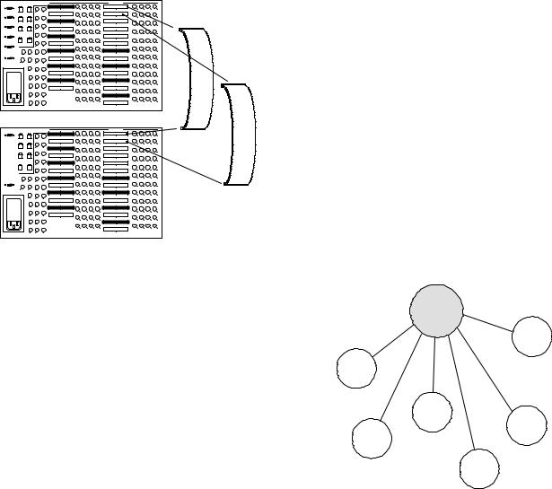
If a TC8802 monitor expansion bay is supplied, each camera that is connected to the TC8801 main CPU bay must also be connected to the same numbered input on the monitor expansion bay.
TC8802 Video Connections
With the TC8802 monitor expansion bay, ribbon cable connectors are provided for the video inputs. Video is to be looped from the main bay into the expansion bay through 16 TC8809 ribbon cables. Connect all TC8809 ribbon cables from the appropriate "VIDEO" ribbon cable connector on the main bay to the corresponding "VIDEO" ribbon cable connector on the monitor expansion bay. The ribbon cable connectors contain a small “key” protrusion formed into one side of the connector to assure proper placement into the mating connectors. Be careful not to force the cables into the mating connectors backwards. The DIP switches on the VIM cards installed in the main bay should be turned OFF. This will make the main bay inputs non-terminated, and the expansion bay will provide the termination for the video inputs.
KEYBOARD |
|
VIDEO |
|
|
|
|
|
VIDEO IN |
|
|
|
|
|
|
|
OUT |
|
|
|
|
|
|
|
|
|
|
|||
CONSOLE |
|
|
|
|
|
|
|
|
|
|
|
|
|
|
|
|
|
|
INPUT 161-176 |
8 |
7 |
6 |
5 |
LOOP 1-16 |
4 |
3 |
2 |
1 |
|
1 |
2 |
13 |
1 |
|
|
|
|
|
|
|
|
|
|
|
ALARM |
|
|
|
|
|
|
|
|
|
|
|
|
|
|
|
|
|
|
LOOP 161-176 |
16 |
15 |
14 |
13 |
LOOP 17-32 |
12 |
11 |
10 |
9 |
|
3 |
4 |
14 |
2 |
|
|
|
|
|
|
|
|
|
|
|
PRINTER |
|
|
|
INPUT 177-192 |
24 |
23 |
22 |
21 |
LOOP 33-48 |
20 |
19 |
18 |
17 |
|
|
|
15 |
3 |
|
|
|
|
|
|
|
|
|
|
|
5 |
6 |
|
|
LOOP 177-192 |
|
|
|
|
LOOP 49-64 |
|
|
|
|
|
SDA |
|
|
|
|
32 |
31 |
30 |
29 |
|
28 |
27 |
26 |
25 |
|
|
|
16 |
4 |
INPUT 193-208 |
|
|
|
|
LOOP 65-80 |
|
|
|
|
|
COMM PORT 1 7 |
8 |
|
|
|
40 |
39 |
38 |
37 |
|
36 |
35 |
34 |
33 |
|
|
|
17 |
5 |
LOOP 193-208 |
|
|
|
|
LOOP 81-96 |
|
|
|
|
|
|
|
|
|
|
48 |
47 |
46 |
45 |
|
44 |
43 |
42 |
41 |
|
COMM PORT 2 32 |
25 |
18 |
6 |
INPUT 209-224 |
|
|
|
|
INPUT 97-112 |
|
|
|
|
|
|
|
|
|
LOOP 209-224 |
56 |
55 |
54 |
53 |
LOOP 97-112 |
52 |
51 |
50 |
49 |
|
SYNC |
26 |
19 |
7 |
|
|
|
|
|
|
|
|
|
||
|
|
|
|
|
|
|
|
|
|
|
||||
IN |
|
|
|
|
|
|
|
|
|
|
|
|
|
|
|
|
|
|
INPUT 225-240 |
64 |
63 |
62 |
61 |
INPUT 113-128 |
60 |
59 |
58 |
57 |
|
|
27 |
20 |
8 |
|
|
|
|
|
|
|
|
|
|
|
|
|
|
|
LOOP 225-240 |
72 |
71 |
70 |
69 |
LOOP 113-128 |
68 |
67 |
66 |
65 |
|
|
28 |
21 |
9 |
|
|
|
|
|
|
|
|
|
|
|
|
|
|
|
INPUT 241-256 |
80 |
79 |
78 |
77 |
INPUT 129-144 |
76 |
75 |
74 |
73 |
|
|
29 |
22 |
10 |
|
|
|
|
|
|
|
|
|
|
|
|
|
|
|
LOOP 241-256 |
88 |
87 |
86 |
|
LOOP 129-144 |
84 |
83 |
82 |
|
|
|
|
|
|
|
85 |
|
81 |
|
||||||
|
30 |
23 |
11 |
|
|
|
|
|
INPUT 145-160 |
|
|
|
|
|
|
31 |
24 |
12 |
TC8801 |
96 |
95 |
94 |
93 |
LOOP 145-160 |
92 |
91 |
90 |
89 |
|
KEYBOARD |
|
VIDEO |
|
|
|
|
|
VIDEO IN |
|
|
|
|
|
|
|
OUT |
|
|
|
|
|
|
|
|
|
|
|||
CONSOLE |
|
|
|
|
|
|
|
|
|
|
|
|
|
TC8809 |
1 |
2 |
13 |
1 |
INPUT 161-176 |
8 |
7 |
6 |
5 |
LOOP 1-16 |
4 |
3 |
2 |
1 |
|
|
|
14 |
2 |
LOOP 161-176 |
16 |
15 |
14 |
13 |
LOOP 17-32 |
12 |
11 |
10 |
9 |
Ribbon |
3 |
4 |
15 |
3 |
|
|
|
|
|
|
|
|
|
|
Cables |
|
|
INPUT 177-192 |
24 |
23 |
22 |
21 |
LOOP 33-48 |
20 |
19 |
18 |
17 |
|||
5 |
6 |
|
|
LOOP 177-192 |
|
|
30 |
|
LOOP 49-64 |
|
|
26 |
|
|
|
|
|
|
|
32 |
31 |
29 |
|
28 |
27 |
25 |
|
||
|
|
16 |
4 |
INPUT 193-208 |
|
|
|
|
LOOP 65-80 |
|
|
|
|
|
|
|
|
|
|
|
|
|
|
|
|
|
|
||
7 |
8 |
|
|
|
40 |
39 |
38 |
37 |
|
36 |
35 |
34 |
33 |
|
|
|
17 |
5 |
LOOP 193-208 |
|
|
|
|
LOOP 81-96 |
|
|
|
|
|
|
|
|
|
|
48 |
47 |
46 |
45 |
|
44 |
43 |
42 |
41 |
|
COMM PORT 2 32 |
25 |
18 |
6 |
INPUT 209-224 |
|
|
|
|
INPUT 97-112 |
|
|
|
|
|
|
|
|
|
LOOP 209-224 |
56 |
55 |
54 |
53 |
LOOP 97-112 |
52 |
51 |
50 |
49 |
|
SYNC |
26 |
19 |
7 |
|
|
|
|
|
|
|
|
|
||
|
|
|
|
|
|
|
|
|
|
|
||||
IN |
|
|
|
|
|
|
|
|
|
|
|
|
|
|
|
|
|
|
INPUT 225-240 |
64 |
63 |
62 |
61 |
INPUT 113-128 |
60 |
59 |
58 |
57 |
|
|
27 |
20 |
8 |
|
|
|
|
|
|
|
|
|
|
|
|
|
|
|
LOOP 225-240 |
72 |
71 |
70 |
69 |
LOOP 113-128 |
68 |
67 |
66 |
65 |
|
|
28 |
21 |
9 |
|
|
|
|
|
|
|
|
|
|
|
|
|
|
|
INPUT 241-256 |
80 |
79 |
78 |
77 |
INPUT 129-144 |
76 |
75 |
74 |
73 |
|
|
29 |
22 |
10 |
|
|
|
|
|
|
|
|
|
|
|
|
|
|
|
LOOP 241-256 |
88 |
87 |
86 |
|
LOOP 129-144 |
84 |
83 |
82 |
|
|
|
|
|
|
|
85 |
|
81 |
|
||||||
|
30 |
23 |
11 |
|
|
|
|
|
INPUT 145-160 |
|
|
|
|
|
|
31 |
24 |
12 |
TC8802 |
96 |
95 |
94 |
93 |
LOOP 145-160 |
92 |
91 |
90 |
89 |
|
Typical TC8809 Connections
TC8802 Data Connections
The TC8802 is supplied with a TC8716C2 data communication interconnect cable with two connectors spaced about 3 feet apart. Install the TC8716C2 cable between the Comm1 port on the TC8801 Main CPU bay, and the Comm1 port on the TC8802 monitor expansion bay.
Keyboard Hookup
Connect a maximum of 8 system keyboards to any of the 8 keyboard ports (modular phone type jacks) provided on the rear of the TC8x01 Main CPU bay, but be sure to at least connect a keyboard to port #1. The TC8500 is limited to these 8 keyboards. Other systems may accommodate 16 or 32 keyboards using TC8714A and TC8715A series keyboard port expander accessory units.
Additional keyboards may also be used with a TC8802A Series Monitor Expansion Bay. Connect the keyboards the same way as with the TC8801A Series Main Bay. DIP switches 2 and 3 of S101 on the Data Receiver module in the Monitor Expansion Bay must now be set according to the table below.
Desired Keyboard Numbers
On Monitor Expansion Bay
Keyboards |
Switch 2 |
Switch 3 |
None |
OFF |
OFF |
9 to 16 |
OFF |
ON (recommended setting) |
17 to 24 |
ON |
OFF |
25 to 32 |
ON |
ON |
Each keyboard is supplied with a 10-foot cable for local hookups. The TC8x01 can provide power to keyboards up to 100 feet away using the optional TC8557HL hookup cable. For distances of up to 5000 feet, the optional TC8557HR hookup kit is required, which is supplied with a remote power pack and requires user-supplied shielded twisted pair (Belden 9841 or equivalent) for communication.
Satellite Configuration Installations
Due to the many variations possible, only general guidelines can be covered for installing satellite systems. Refer to the appendix section of this manual, the TC8850 Graphical User Interface Software manual or the TC8x59 Master Control Software package manual for additional configuration and programming information on satellite systems.
Central
Control
Station
Video and
Data Links Satellite
System
#6
Satellite
System
#1
|
Satellite |
|
|
System |
|
|
#3 |
Satellite |
|
|
|
|
|
System |
Satellite |
|
#5 |
System |
|
|
#2 |
|
|
|
|
Satellite |
|
|
System |
|
|
#4 |
|
|
S9507002AE |
Satellite Concept Configuration
23
Satellite Site “Trunk Line”
Monitor Outputs
At each of the remote satellite sites, a desired number of monitor outputs from the switcher must be assigned as Trunk lines. The number of Trunk lines can range from 1 to the maximum number of monitor outputs that the switcher provides. Note that the number of Trunk lines coming from a satellite site determines the maximum number of different cameras from that site that may be viewed simultaneously at the Main site. If operators will be stationed at the satellite site, they should be prevented from accessing the monitor outputs designated as Trunk lines. This can be accomplished via the Monitor Lockout tables using either the TC8850 Graphical User Interface Software package or the TC8x59 Master Control Software package (see below).
Main Site “Trunk Line” Video Inputs
At the main site, video Trunk line connections coming from each of the remote site(s) should be connected (and properly terminated) using any available video input at the main bay. There are no programming restrictions concerning their connections, but a sense of order can be maintained if a group of video inputs are used at the upper end of the system’s designed capacity. This allows the main system to be more easily expanded in the future with either additional local cameras or additional Trunk lines. As an example, assume that there are a total of 8 Trunk lines coming from all satellite sites which will be connected to a main site system designed for 32 inputs. Inputs 25 to 32 can be reserved for the Trunk lines leaving inputs 1 to 24 for local camera connections. If there will be no local camera inputs, then the Trunk lines can start at the first video input.
Control Data Lines in Satellite Systems
Each satellite site must be provided with an Allegiant control data line coming from the Signal Distribution unit (usually a TC8568) at the Main site. This data line carries all pan/tilt/zoom control commands in addition to the switching commands generated by the Main site switcher. The control data line should be connected to a TC8780 Series Data Converter unit which will be used to provide the address decoding functions for the satellite site. A TC8780 Series unit is required at each satellite site and must be given a unique site address number.
If operators will be stationed at the satellite site and are permitted to control pan/tilt/zoom equipped cameras, a TC8569-2 Series Code Merger unit must be installed at the satellite site. The Code Merger will combine the code generated by the main site and the satellite site so both sites have control over pan/tilt/zoom equipped cameras located at the satellite site. The TC8780 Series unit can then be
connected to one of the data outputs of the TC8569- 2 Series unit.
Satellite Site Programming Requirements
The optional TC8850 Graphical User Interface Software (GUI) package or the TC8x59 Master Control Software (MCS) package is required to properly program a satellite system. With the TC8x59 Master Control Software, it is necessary that an appropriate version of the program be available for each type (TC8300 Series, TC8500 Series, TC8600 Series, and/or TC8800 Series) of Allegiant system being used in the system.
If a single Master Control Software package is purchased, its security device and cable can be used with any of the program disks which are now supplied with a system’s CPU module to properly configure a Satellite system.
Programming the satellite sites is usually limited to designating their ‘logical’ camera numbers to appropriate values via the Camera ID Table of the GUI or MCS. If TC8112B Series or TC8124B Series are being used as satellite switchers, the starting camera number can be designated using their onscreen programming menus.
THE STARTING CAMERA NUMBER SHOULD NOT BE CHANGED IN TC8112B OR TC8124B SERIES SITES WHERE LOCAL PAN/TILT/ZOOM EQUIPPED CAMERAS WILL BE USED SINCE THE TC8135B SERIES CONTROLLER FOLLOWER CAN ONLY ADDRESS NUMBERS FROM 1 TO 24.
Note that there can be no duplicate camera numbers anywhere in the system. Allegiant logical camera designations can be renumbered to any four digit number on TC8300, TC8600 Series or TC8800 Series systems, and any three digits on TC8500 systems. Only two digit camera numbers can be selected with TC8112B or TC8124B Series switchers. There are few other restrictions. These camera numbers will be the numbers entered at both the satellite and the main site keyboards when camera selections are made. On any pan/tilt/zoom equipped camera, this logical number must also be entered as the receiver/driver’s site address number.
To maintain a sense of order, it is generally preferable if a satellite is programmed for a range of camera numbers. For example, in a three Allegiant type satellite system, the first satellite can be programmed for camera numbers 1 to 50. Satellite two can be programmed for camera numbers 101 to 131, and satellite three can use numbers 201 to 225.
If necessary, the GUI or MCS software’s Keyboard- to-Monitor Lockout Table can be programmed in the satellite switcher to prevent any local operators from inadvertently accessing the satellite’s monitor outputs being used as Trunk lines. Once TC8112B/TC8124B Series switchers are configured for satellite operation (via their on-screen menu
24
setup), the monitor outputs being used as Trunk lines are automatically disabled from local control as soon as the first commands are received from the main site.
If operators will be stationed at the satellite site, camera titles should be entered into the switcher. If desired, these titles can be selected (explained below) to appear at the main site.
The only other requirement is to ensure that the Console ports of all Allegiant type satellites have their handshake option disabled (CTS = off). This is done via the GUI software, the MCS’s ParametersSystem screen, or via the system’s Keyboard User Functions (as described later in this manual). This requirement does not apply to TC8112B/TC8124B Series switchers.
Main Site Programming Requirements
At the main site, the GUI or MCS program’s Camera ID table must be configured to ensure proper satellite operation. Usually it is easiest to start with the Trunk line inputs. For each Trunk line, the satellite’s monitor output number and its ‘Bay’ address (the same number the satellite’s TC8780 Series unit is set to) must be entered.
Camera numbers should be programmed next. Note that no duplicate camera numbers are allowed anywhere in the entire system. Remote cameras (those located at the satellite sites) should be designated using numbers above those corresponding to the main bay’s physical video inputs (32+ on TC8300, 65+ on TC8500, 129+ on TC8600, 257+ on TC8800). Enter the desired camera number, the Satellite Bay that it is actually connected to, and select if either a local title will be used or if the remotely generated title will be used. For the satellite camera entries, only those numbers which represent
actual cameras need to be entered. For example, all 12 cameras associated with a 12-position TC8112B switcher do not need to be entered if only 5 cameras are actually connected to the switcher. If desired, a few extra camera numbers may be included at this time if the satellite site will be expanded in the future. If a local title is specified, the camera’s title can also be entered at this time. Designate any local camera numbers appropriately and enter their corresponding titles. Note that either a local camera or a remote camera programmed with a local title will need to be selected to view certain on-screen prompts or data during programming of the main site via a system keyboard.
Once the system is programmed and configured, any unused monitor outputs (those with no physical monitors connected to them) located at the main site should be selected to display a local camera via the system keyboard. This prevents unused monitor outputs from using up Trunk lines which may result in some confusing operational responses.
Alarm Inputs in Satellite Systems
Any alarm inputs to the main site which have been programmed to activate cameras located at satellites will operate in the 'normal' way except when limited by the number of Trunk lines available. The software will automatically determine Trunk usage depending upon the priority level of operators currently viewing satellite cameras. Note that alarm inputs applied at a satellite site will NOT activate alarm video at the main site. If the application requires alarms located at a satellite to activate video at the main site, then the remote alarms must be brought back to the main site. In some cases, the main site's TC8540C Alarm Interface unit can be remotely located via a RS-232 link. If more than one satellite site contains alarms, then multiple TC8540C alarm interfaces can be remotely located. The number of alarm interfaces which can be remoted is only limited by the capacity of the main site system to support this capability.
25
Feature Selection
Certain user-selectable features can provide enhanced Allegiant system operation capabilities. Any desired changes can be made now or delayed until specific system requirements become more apparent. Refer to the section on FACTORY DEFAULT SETTINGS for a full description of these features and selection instructions.
Main Power Connections
Install supplied AC power cord(s) between the bay(s) and appropriate AC power source. Verify that power supply is configured for desired voltage input. If necessary, instructions for changing the input voltage selection can be found in the Maintenance section of this manual. Switch power ON to the bay(s). In multibay systems, the bays can be powered up in any order.
NOTE: The system may require several seconds to fully initialize after a power-up reset. Up to 1 minute may be required before a TC8802 monitor expansion bay fully initializes. This time can vary based on the activity and general size of the system.
Verify that the LEDs associated with the fuses are lit on all of the applicable power supplies.
NOTE: UPON POWER UP, THE SYSTEM MONITORS WILL MOMENTARILY DISPLAY VIDEO OUTPUT MODULE SOFTWARE VERSION INFORMATION.
Installations having cameras powered from an AC phase different than that of the Allegiant system may utilize the built in EXTERNAL SYNC input or vertical PHASE ADJUST.
NOTE: ALL CAMERAS SHOULD BE PHASED PROPERLY WITH EACH OTHER BEFORE THE EXTERNAL SYNC OR PHASE ADJUST FEATURE IS IMPLEMENTED.
The EXTERNAL SYNC input will accept composite video, composite sync, or the output of a Master Sync generator. Any one of the phased cameras may be used as a master sync source to the system using the EXTERNAL SYNC input. To implement this feature, simply connect the incoming video source (using a BNC "T" connector) to both the appropriate camera BNC input and the EXTERNAL SYNC input which is found on the rear of the TC8x01 main CPU bay. The EXT SYNC LED on the front panel of the power supply will light. Alternatively, the PHASE ADJ on the front panel of the power supply may be adjusted until vertical interval switching is achieved. The PHASE ADJUST has a range of about 130 degrees.
Reattach the front panel(s) to the bay(s).
Proceed to the next applicable accessory installation section or immediately to the appropriate system operating instruction section.
26
 Loading...