


LV009
Bosch LV009, LV012, LV007, LV018, LV024 Installation And Maintenance Manual
...
LV MODEL
Installation and Maintenance Manual
8733944336 (2016/09)
2 | LV Heat Pump Series
CONTENTS
Key to Symbols...................................................................3
Safety Warnings.................................................................3
Model Nomenclature...........................................................4
General Description............................................................5
Moving and Storage............................................................5
Installation.........................................................................5
Step1 Check Job Site....................................................5
Step 2 Check Unit.........................................................5
Step 3 Locate Unit...................... ...................................6
Step 4 Mount The Unit...................................................7
Hanging Bracket Kit.......................................................8
Step 5 Check Duct System......... .....................................9
Step 6 Install Condensate Drain................. ......................9
Step 7 Pipe Connections..............................................10
Step 8 Wire Power Supply............................................10
Step 9 Wire Field Controls............................................12
Unit Controls ECM-UPM....................................................12
ECM Interface Board...................................................12
Safety Devices and the UPM control..............................12
Safety Features..........................................................13
Freeze Sensor............................................................14
Intelligent Reset..........................................................14
Lockout reset.............................................................14
Pre- Start- Up..................... ...............................................15
Air Coil......................................................................15
Units Mounted Non-Fused Disconnect Switch.................22
Hot Gas Reheat..........................................................24
Hot Gas Bypass..........................................................25
Internal 2-Way Water Valve..........................................25
Economizer...............................................................25
Certified Performance Table.............................................26
Fan Motors Options...........................................................27
Permanent Split Capacitor Motors (PSC)........................27
Constant Torque Motors (ECM).....................................28
Constant Airflow Motors (ECM).....................................30
Standard Blower Motor................................................32
Constant Torque ECM Blower Motor..............................33
Constant CFM ECM Blower Motor..................................34
Troubleshooting...............................................................35
Temperature Pressure Table.............................................40
Waterside pressure Drop Table..........................................46
Compressor Characteristics..............................................47
Corner Weights (HZ).........................................................48
Water Coil Volume............................................................48
Wiring Diagrams...............................................................49
Dimensional Drawings......................................................56
Vertical............................................................................56
Horizontal........................................................................57
Start Up...........................................................................15
Operating Limits........................................................ 15
Environment..............................................................15
Power Supply.............................................................15
Unit Starting Conditions...............................................15
Scroll Compressor Rotation..........................................16
Sequence Of Operation UPM........................................17
Sequence Of Operation ECM.......... ...............................18
Unit Start Up Cooling Mode...........................................19
Unit Start Up Heating Mode................. ..........................19
Flow Regulation..........................................................19
Antifreeze..................................................................20
Application Considerations...............................................20
Well Water Systems....................................................20
Cooling Tower/Boiler Systems......................................21
Geothermal Closed Loop Systems.................................21
Open Well Water Systems............................................22
Water Quality...................................................................22
Water Quality Table..........................................................23
Condensate Connections..................................................23
Piping..............................................................................24
Options............................................................................24
Extended Range.........................................................24
Maintenance....................................................................59
Information On Decommissioning......................................59
Protecting The Environment..............................................59
Components..............................................................59
Refrigerant................................................................59
Terminology.....................................................................60
Unit Check Out Sheet........................................................61
Notes...............................................................................62
LV Heat Pump Series8 733 944 336 (2016/09) Subject to change without prior notice
Key to Symbols | 3LV Heat Pump Series
KEY TO SYMBOLS
Warnings
Warnings in this document are identified by
a warning triangle printed against a grey
background. Keywords at the start of the
warning indicate the type and seriousness
of the ensuing risk if measures to prevent
the risk are not taken.
The following keywords are defined and can be used in
this document:
• DANGER indicates a hazardous situation which, if
not avoided, will result in death or serious injury.
• WARNING indicates a hazardous situation which, if
not avoided, could result in death or serious injury.
• CAUTION indicates a hazardous situation which, if
not avoided, could result in minor to moderate
injury.
• NOTICE is used to address practices not related to
personal injury.
Important Information
This symbol indicates important information where
there is no risk to property or people.
SAFETY WARNINGS
IMPORTANT: Read the entire instruction
manual before starting installation.
DANGER: Improper installation,
adjustment, alteration, service,
maintenance, or use can cause explosion,
fire, electrical shock or other conditions
which may cause personal injury or property
damage. Consult a qualified installer,
service agency, or your distributor or branch
for information or assistance. The qualified
installer or agency must use factoryauthorized kits or accessories when
modifying this product. Refer to the
individual instructions packaged with the
kits or accessories when installing.
WARNING: Before performing service or
maintenance operations on the system, turn
off main power to the unit. Electrical shock
could cause personal injury or death.
WARNING: When working on equipment,
always observe precautions described in
the literature, tags, and labels attached to
the unit. Follow all safety codes. Wear
safety glasses and work gloves. Use a
quenching cloth for brazing, and place a fire
extinguisher close to the work area.
NOTICE: To avoid the release of refrigerant
into the atmosphere, the refrigerant circuit
of this unit must be serviced only by
technicians who meet local, state, and
federal proficiency requirements.
NOTICE: All refrigerant discharged from this
unit must be recovered WITHOUT
EXCEPTION. Technicians must follow
industry accepted guidelines and all local,
state, and federal statutes for the recovery
and disposal of refrigerants. If a compressor
is removed from this unit, refrigerant circuit
oil will remain in the compressor. To avoid
leakage of compressor oil, refrigerant lines
of the compressor must be sealed after it is
removed.
NOTICE: To avoid equipment damage, DO
NOT use these units as a source of heating
or cooling during the construction process.
Doing so may affect the unit’s warranty. The
mechanical components and filters will
quickly become clogged with construction
dirt and debris, which may cause system
damage.
WARNING: Installation and servicing of this
equipment can be hazardous due to system
pressure and electrical components. Only
trained and qualified personnel should
install, repair, or service the equipment.
8 733 905 683 (2016/09)LV Heat Pump Series
//9 97& )/738% ;; 6$0;; ; ; $;; ; ;; ; ; 6%$
GENERAL ELECTRICAL OPTIONS (UP TO 5 AVAILABLE PER UNIT)
A-EMS RELAY
B-BLOWER MONITOR RELAY
C-COMPRESSOR MONITOR RELAY
D-PHASE MONITOR
E-PUMP/VALVE RELAY
G-BOILERLESS CONTROL
H-FLOW PROVING SWITCH
J-DISCONNECT SWITCH
K-FIRE ALARM RELAY/DUAL POWER
M-WIRE TO 208 V
X-AS DEFAULT FOR NON USED ELECTRICAL CODES
VOLTAGE
0 115/60/1
1 208-230/60/1
2 277/60/1
3 208-230/60/3
4 460/60/3
5 575/60/3
8 220-240/50/1
A 380-420/50/1
SIZE
007, 009, 012, 015,
018, 024, 030, 036,
041, 042, 048, 060,
070
LV
CABINET CONFIGURATION
HZ-HORIZONTAL
VT-VERTICAL
CF-COUNTERFLOW
COAX OPTIONS
C-COPPER
N-CUPRO-NICKEL
WATER CONNECTIONS
F-FRONT
B-BOTTOM
M-MARINE
RETURN AIR CONFIGURATION
L-LEFT
R-RIGHT
DISCHARGE AIR CONFIGURATION
T-TOP
S-STRAIGHT
E-END
B-BOTTOM
FAN/MOTOR OPTIONS
P-STANDARD PSC
A- CONSTANT AI RFLOW ECM
T-CONSTANT TORQUE ECM
AIR COIL
U-UNCOATED
D-DUOGUARD
REVISION LEVEL
B-CURRENT
ELECTRIC HEAT
(SINGLE POINT)
X-NONE
A-5kW
B-7.5kW
C-10kW
CABINET CONSTRUCTION
A-GALVANIZED STEEL/1/2” STANDARD 1.5LB DUAL DENSITY FIBERGLASS
C-A-GALVANIZED STEEL/1/2” CLOSED CELL FOAM
D-A-GALVANIZED STEEL/1/2” STANDARD 1.5LB DUAL DENSITY FIBERGLASS, EXTRA QUIET
F-A-GALVANIZED STEEL/1/2” CLOSED CELL FOAM, EXTRA QUIET
APPLICATION
T-TXV OPTION
S-STANDARD RANGE
G-EXTENDED RANGE
AIR FILTRATION
1- STANDARD THROWAWAY FILTER W/4 SIDED FILTER RACK
4-MERV8-2” W/4 SIDED FILTER RACK
5-MERV13-2” W/4-SIDED FILTER RACK
REFRIGERATION CIRCUIT OPTIONS
X-NONE
H-HOT GAS REHEAT-ON OFF
B-HOT GAS BYPASS
C-HOT GAS BYPASS WITH HOT GAS REHEAT
S-STRAIGTH COOL
CONTROLS
X-NONE
M-DDC(MULTI PROTOCOL)(BACNET, MODBUS, N2
L-DDC-LONWORKS
WATER FLOW CONTROL OPTIONS
X-NONE
2-2 WAY SOLENOID VALVE
3-MEASURE FLOW (3GPM/TON)
4-2 WAY SOLENOID +MEASUREFLOW
6-WATER REGULATING VALVE CONNECTION
TRANSFORMER
4-40 VA
5-50 VA
7-75 VA
1-100 VA
STANDARD/SPECIAL
S-STANDARD
A-SPECIAL #1
B-SPECIAL #2
AGENCY OPTIONS
X-ETL (UL 1995)
C-CE (50 HZ ONLY)
E-ETL W/E-HEAT AND SINGLE POINT POWER
ECONOMIZER
X-NONE
E-ECONOMIZER WITH 3 WAY VALVE AND CONTROLS
CODE STRING LEVEL
CHANNEL
B-BOSCH
4 | Model Nomenclature LV Heat Pump Series
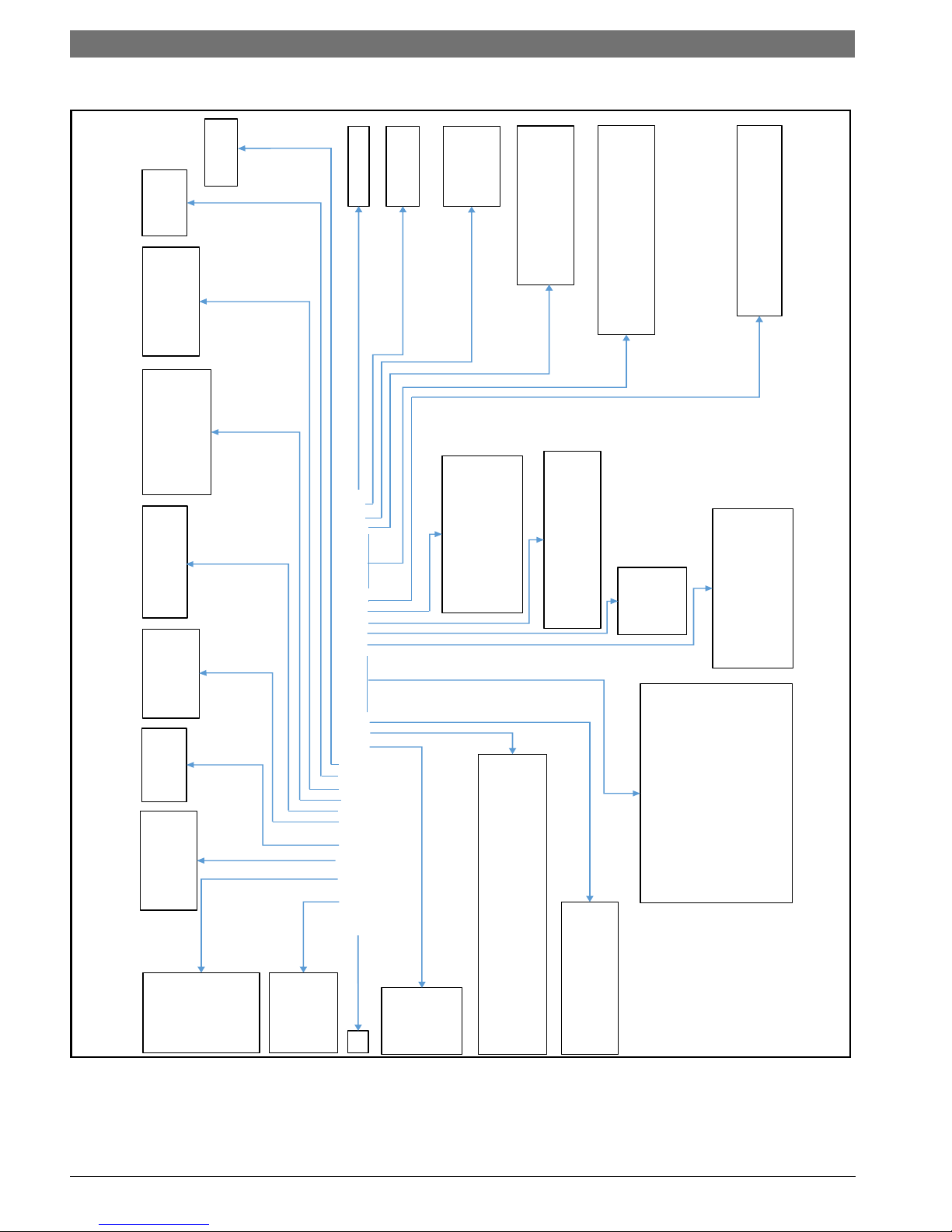
MODEL NOMENCLATURE
Not all Options are available on all models.
Figure # 1
LV Heat Pump Series8 733 944 336 (2016/09) Subject to change without prior notice
General Description | 5LV Heat Pump Series
GENERAL DESCRIPTION
The LV series water-to-air heat pump provides an
unmatched combination of performance, features and
flexibility for both high performance new construction
applications and replacement of existing water-to-air
heat pumps. All units are certified by the Air
conditioning, Heating and Refrigeration Institute (AHRI)
to AHRI/ANSI/ASHRAE/ISO standard 13256-1 for waterto-air and brine-to-air heat pumps at both Water Loop
Heat Pump and Ground Loop Heat Pump application
points.
All Water-to-Air Heat Pumps conform to UL 1995
standard and are certified to CAN/CSA C22.2 No 236 by
Intertek-ETL.
These units meet all current applicable requirements of
ASHRAE 90.1.
LV series units are designed to operate with entering
fluid temperatures between 50°F and 100°F in cooling
and 50°F and 80°F in heating with the base
configuration. With the extended range option, LV series
models can operate with entering fluid temperatures
between 50°F and 110°F in cooling and between 20°F
and 80°F in heating. LV units can accommodate a wide
range of air temperatures, however, standard LV models
should not be used for 100% outside air without
consulting the factory applications group. 100% outside
air routinely requires higher levels of dehumidification
than is available from equipment designed for return air
applications.
LV series units are available in three basic
configurations: vertical top supply air (VT), horizontal
end supply air or straight through supply air (HZ) and
counter flow down supply air (CF). Each of these
configurations are available with either left or right hand
return air. HZ models can have the supply air field
converted from end discharge air to straight through
with no extra parts required.
LV units are designed and rated for indoor installation
only. LV units should not be installed in environments
that fall below freezing or exceed 100°F ambient. LV
cabinets are constructed of heavy gauge G-90 galvanized
steel and will resist most common types of corrosion for
the life of the equipment.
LV series units are offered with a wide range of factory
installed options including: PSC, constant torque ECM
or constant air flow ECM fan motors; hot gas reheat; hot
gas bypass; internal 2 way valves; tin plated air coils;
2“4-sided filter racks; MERV 13 filters (with constant
airflow ECM motors); on board DDC controls; copper or
cupro nickel water coils; water-side economizers and
more refer to the unit model number for installed
options..
Note that some options are offered in limited sizes
and/or voltages.
On board safety features will protect the major unit
components from damage under most foreseeable
installation and operation problems.
MOVING AND STORAGE
If the equipment is not needed for immediate
installation upon arrival at the job site, it should be left
in its packaging and stored in a clean, dry area.
Units must be moved and stored in the normal upright
position at all times.
Use caution to avoid damage to filter racks and duct
flanges when storing or handling units.
NOTICE: Never lift or move units by filter
racks, external piping or attached options/
accessories.
NOTICE: Never stack units when
transporting them.
NOTICE: When storing units:
Do not stack units larger than 6 tons
capacity!
Do not stack vertical or counter flow units
under 6 tons capacity more than 2 high
Do not stack horizontal units 6 tons capacity
more than 3 high
INSTALLATION
Step 1- Check Job Site
Installation, operation and maintenance instructions are
provided with each unit. Before unit start-up, read all
manuals and become familiar with unit and its operation.
Thoroughly check out the system before operation.
Complete the inspections and instructions listed below
to prepare a unit for installation.
Horizontal Units
LV units are designed for indoor installation only. Be
sure to allow adequate space around the unit for
servicing.
Vertical Counter flow Units
LV Units are designed for indoor installations only.
While vertical units are typically installed in a floor-level
closet or a small mechanical room, the unit access
guidelines for these units are very similar to those
described for horizontal units.
Step 2- Check Unit
Upon receipt of shipment at the job site, carefully check
the shipment against the bill of landing. Make sure all
units have been received. Inspect each unit for damage.
Ensure the shipping company makes proper notation of
any shortages or damage on all copies of the freight bill.
Concealed damage not discovered during unloading
must be reported to the shipping company.
Please inspect the product carefully for any defects or
discrepancies.
Should you identify any issue, contact the Bosch
Wholesaler / Distributor you purchased the unit from.
8 733 905 683 (2016/09)LV Heat Pump Series
6 | Installation LV Heat Pump Series
1. Be sure that the location chosen for unit installation
provides ambient temperatures maintained above
freezing.
2. Be sure the installation location is isolated from
sleeping areas, private offices and other acoustically
sensitive spaces.
3. Be sure unit is mounted at a height sufficient to
provide an adequate slope of the condensate lines.
If an appropriate slope cannot be achieved, a fieldsupplied condensate pump may be required.
4. On horizontal units, allow adequate room below the
unit for condensate drain trap and do not locate the
unit above supply piping.
5. Provide sufficient space for duct connection. do not
allow the weight of the duct work to rest on the unit.
6. Provide adequate clearance for filter replacement
and drain pan cleaning. Do not allow piping,
conduit, etc. To block filter access.
7. Provide sufficient access to allow maintenance and
servicing of the fan and fan motor, compressor and
coils. Removal of the entire unit from the closet
should not be necessary.
8. Provide an unobstructed path to the unit within the
closet or mechanical room. Space should be
sufficient to allow return air to freely enter the
space.
9. Provide ready access to water valves, fittings, and
screwdriver access to unit side panels, discharge
collar, and all electrical connections.
10. Where access to side panels is limited, pre-removal
of the control box side mounting screws may be
necessary for future servicing.
Protection
Once the units are properly positioned on the job site,
cover them with either a shipping carton, vinyl film, or an
equivalent protective covering. Cap opens ends of pipes
stored on the job site. This precaution is especially
important in areas where painting, plastering or spraying
of fireproof material, etc. Is not yet complete. Foreign
material that accumulates within the units can prevent
proper start-up and require costly clean-up operations.
Before installing any of the systems components, be
sure to examine each pipe, fitting valves and remove any
dirt or foreign material found in or on these components.
Inspect Unit
1. Compare the electrical data on the unit nameplate
with ordering and shipping information to verify that
the correct unit has been shipped.
2. Verify that the unit is the correct model for the
entering water temperature of the job.
3. Do not remove the packaging until the unit is ready
for installation.
4. Verify that the refrigerant tubing is free of kinks or
dents, and that it does not touch other unit
components.
5. Inspect all electrical connections. Be sure
connections are clean and tight at the terminals.
6. Remove any blower support styrofoam from
underneath the blower.
7. Remove any shipping brackets from the unit
attached to the pallet.
Step 3- Locate the Unit
Locate the unit in an indoor area that allows easy access
to the filter, front access panel and blower access panel,
and has enough room for service personnel to perform
maintenance and repair work. Provide sufficient room to
make fluid, electrical and duct work connections.
Locate the unit in conditioned space and avoid
installation in corrosive environments.
If the unit is installed in a confined space, such as a
closet, provisions must be made for return air to freely
enter the face of the unit’s air coil.
Unit condensate drains are not internally trapped.
Allow room below the unit base for horizontal and
counter flow models for an adequate condensate trap.
NOTICE: These units are not approved for
outdoor installation; therefore, they must
be installed inside the structure being
conditioned space. Do not locate in areas
that are subject to freezing.
NOTICE: Do not locate the unit above
supply piping.
Do not locate the unit in areas subject to
freezing or in areas subject to temperature
or humidity extremes.
NOTICE: LV series packaged units are not
approved for outdoor installation. Units
must be installed in conditioned space that
is not subject to extremes of temperature or
humidity to avoid cabinet sweating and/or
equipment damage.
NOTICE: Do not use LV series units for
temporary heating, air conditioning or
ventilation during construction, especially
when plastering, sanding or painting. Care
should be taken to avoid introduction of
dust, paint or debris into the air coil.
LV Heat Pump Series8 733 944 336 (2016/09) Subject to change without prior notice
Installation | 7LV Heat Pump Series
Vibration
Mounting
Pad
Step-4 Mount The Unit
Duct Flanges
The Unit heat pump feature foldout return and supply air
duct flanges. These fold-out flanges allow the heat
pumps to more easily fit through doorways and other
tight spaces, and also prevent damage in shipping and
handling.
It is recommended that all fold-out flanges be folded out
once the heat pump is installed to ensure that return and
supply airflow is not obstructed. These Flanges can be
easily folded using standard or duckbill pliers.Once
folded out these flanges can be used to support light
duct work loads.
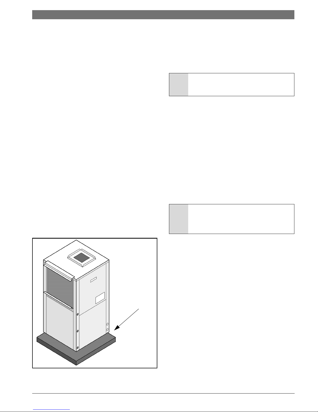
Mounting Vertical Units
LV Series vertical and counter flow units should be
mounted level on a vibration absorbing pad slightly
larger than the unit base in order to minimize vibration
transmission from the unit to the building structure. See
Figure #2 It is generally not necessary to anchor the unit
unless required by local code.
All major service access for the LV Series vertical and
counter flow models is from the front side of the unit.
When installing the unit in a confined space such as a
closet, ensure that the service panel screws are
accessible, that the filter can be replaced without
damage and that water and electrical connections are
accessible. For models with a unit mounted disconnect
switch, make sure the switch can be easily seen and
operated.
To reduce sound transmission, units should be installed
using flexible electrical conduit and hose kits. Care
should be taken to ensure that no part of the unit
cabinet is touching part of the building structure. For
ducted return applications, a flexible duct connection
should be used.
Mounting Horizontal Units
While horizontal units may be installed on any level
surface strong enough to hold their weight, they are
typically suspended above a ceiling by threaded rods.
The rods are usually attached to the unit corners by
hanger bracket kits included with the unit.
NOTICE: Horizontal (HZ) units must be
installed pitched toward the condensate
drain connection 1/8” per foot.
Horizontal units installed above the ceiling must
conform to all local codes. An auxiliary drain pan if
required by code, should be at least four inches larger
than the bottom of the heat pump.
Plumbing connected to the heat pump must not come in
direct contact with joists, trusses, walls, etc. Some
applications require an attic floor installation of the
horizontal unit. In this case the unit should be set in a full
size secondary drain pan on top of a vibration absorbing
mesh.
The secondary drain pan prevents possible condensate
overflow or water leakage damage to the ceiling. The
secondary drain pan is usually placed on a plywood base
isolated from the ceiling joists by additional layers of
vibration absorbing mesh. In both cases, a 3/4” drain
connected to this secondary pan should be run to an
eaves at a location that will be noticeable.
NOTICE: If the unit is located in a crawl
space, the bottom of the unit must be at
least 4" above grade to prevent flooding of
the electrical parts due to heavy rains.
Figure # 2 Mounting Vertical Units
8 733 905 683 (2016/09)LV Heat Pump Series
8 | Installation LV Heat Pump Series
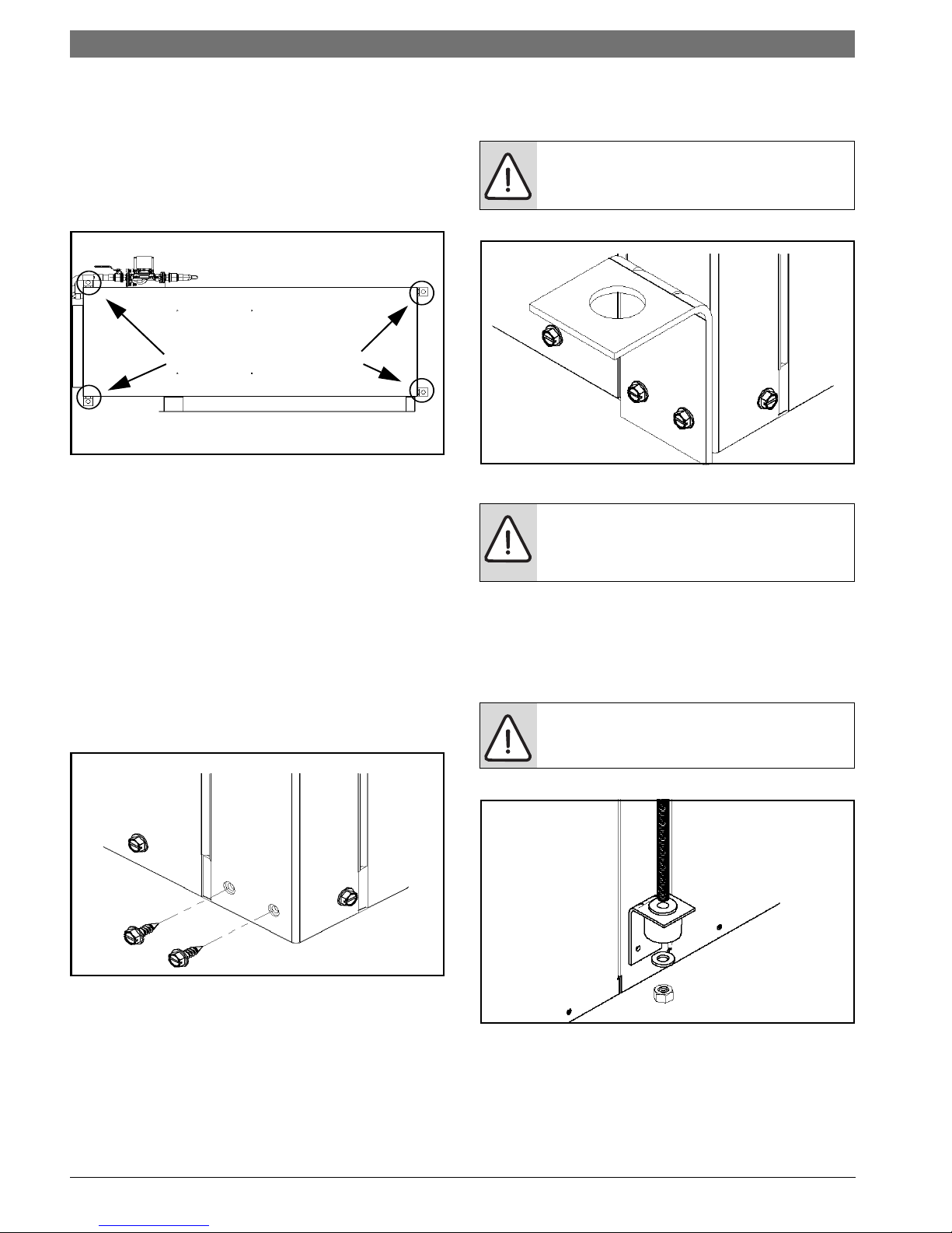
Hanging Brackets Locations
Hanging Bracket Kit
Installation instructions
All horizontal units come with Hanging Bracket Kit
to facilitate suspended unit mounting using threaded
rod. Hanging Brackets are to be installed as shown in
Figure#3
Figure # 3
This kit includes the following:
(5) Brackets
(5) Rubber Vibration Isolators
(8) Screws # 10x1/2”
(10) Bolts 1/4-28x1/2” hex Bolt (not used on this
model)
The following are needed and are to be field provided:
Threaded rod (3/8” max dia)
Hex Nuts
Washers (1-3/4” min O.D.)
1. Remove and discard factory provided screws from
location where Hanging Brackets will be installed shown
in Figure#4
2. Mount 4 Brackets to unit corner post using the bolts
provided in the kit as shown on Figure # 5
WARNING: Do not re-use screws removed
from the unit on step 1 to mount the
hanging Brackets to the unit.
Figure # 5
WARNING: Follow all applicable codes
requirements when hanging this unit.
Selecting threaded rod material, etc.
3. Install Rubber Grommet on the bracket as shown in
Figure# 6.
4. Hang the unit and assemble the field provided Thread
Rod, Nuts and Washers on to the Brackets as shown in
Figure# 6.
DANGER: Rods must be securely anchored
to the ceiling.
Figure # 4
Figure # 6
LV Heat Pump Series8 733 944 336 (2016/09) Subject to change without prior notice
Installation | 9LV Heat Pump Series
Step-5 Check Duct System
All units are provided with a return air duct flange and
supply air duct connections. Refer to unit dimensional
drawings (Page# 55).
A flexible duct connector is recommended for supply
and return air duct connections on metal duct systems.
All metal ducting should be insulated with a minimum of
1”inch duct insulation to avoid heat loss or gain and
prevent condensate from forming during the cooling
operation. Application of the unit to uninsulated duct
work is not recommended as the unit’s performance will
be adversely affected.
If the unit will be installed in a new installation with new
duct work, the installation should be designed using
current ASHRAE procedures for duct sizing. If the unit
will be connected to an existing duct system, a check
should be made to assure that the duct system has the
capacity to handle the air required for the unit
application. If the duct system is too small, larger duct
work must be installed. Be certain to check for existing
leaks and repair.
The duct system and all diffusers should be sized to
handle the designed air flow quietly. To maximize sound
attenuation of the unit blower, the supply and return air
plenums should be insulated. There should be no direct
straight air path through the air grill into the heat pump.
The return air inlet to the heat pump must have at least
one 90° turn away from the space return air grill. If air
noise or excessive air flow are a problem, the blower
speed can be changed to a lower speed to reduce air
flow.
6. Turn the blower panel 180
support brackets are now at the bottom of the
blower.
7. Insert the blower panel with the blower and motor
into the desired location. Be careful not to damage
the refrigerant coils or any other internal unit
components. Screw the panel into place.
8. Replace the wires between the blower motor and
electrical box. Make sure to connect wires to the
proper speed taps.
9. Replace the blower access panel.
10. Reconnect power to the unit.
°
so that the blower
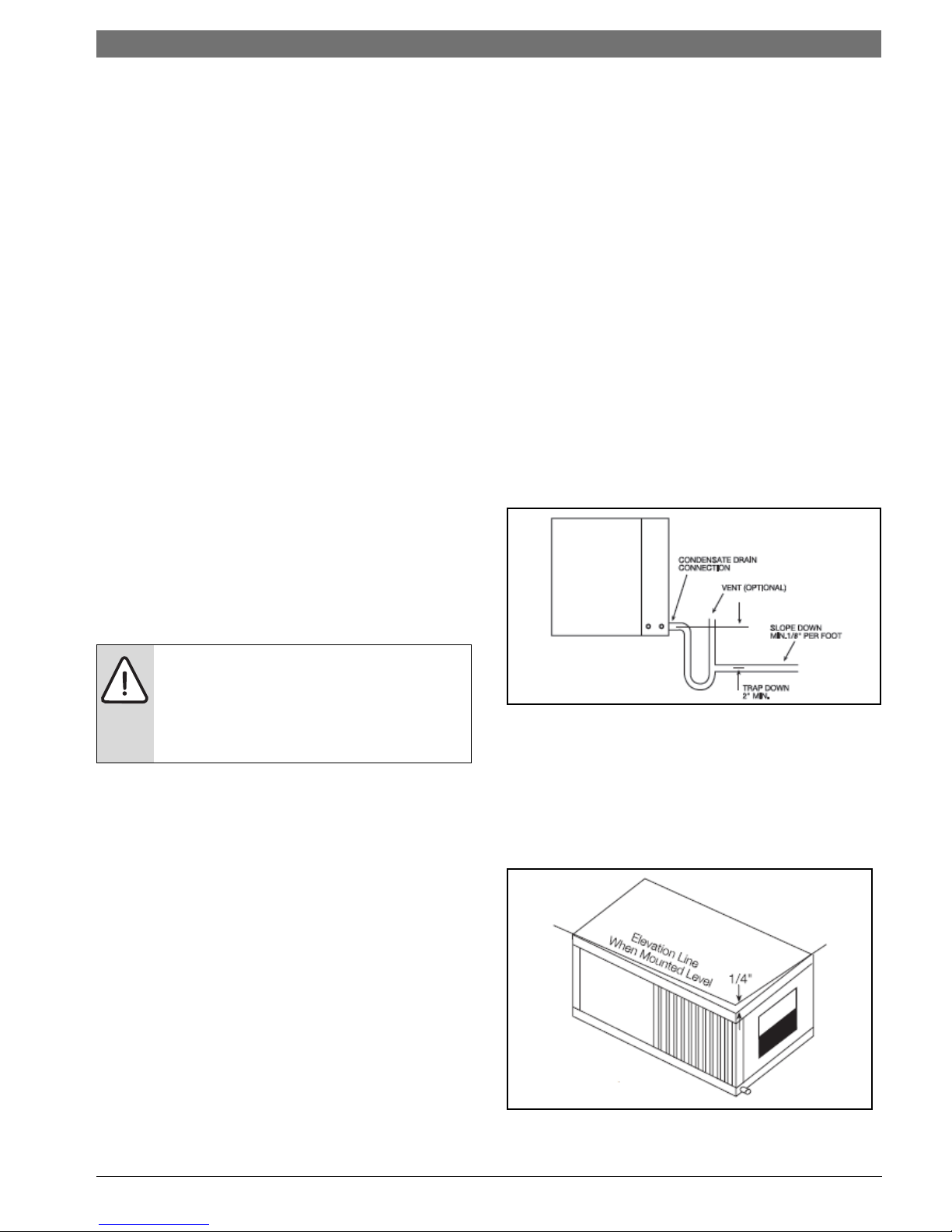
Step 6-Install Condensate Drain.
A drain line must be connected to the heat pump and
pitched away from the unit a minimum of 1/8-inch per
foot to allow the condensate to flow away from the unit.
This connection must be in conformance with local
plumbing codes. A trap must be installed in the
condensate line to ensure free condensate flow. (Heat
pumps are not internally trapped). A vertical air vent is
sometimes required to avoid air pockets.
(See figure # 7)
.
Do not connect discharge ducts directly to
the blower outlet. Use ashrae guidelines for
duct sizing
The factory filter rack should be left in place
on a free return system.
Horizontal Supply Air Configuration
Conversion
The supply air location on horizontal units can be quickly
field converted from end blow to straight through or vice
versa. To convert the supply air direction, follow the
steps below:
1. If connected to power, shut off the unit and
disconnect switch or circuit breaker.
2. Unscrew and remove the blower access panel.
3. Disconnect the wires from the unit electrical box to
the blower motor. Note which speed taps are wired
for units with PSC or constant torque motors.
4. Unscrew and carefully remove the blower panel with
the blower and motor attached. Be careful not to
damage the refrigerant coils or any other internal
unit components.
5. Remove the blower support brackets from the
bottom of the blower housing and relocate them to
the top of the blower housing.
Figure # 7 Condensate Drain
The depth of the trap depends on the amount of positive
or negative air pressure on the drain pan while the unit
fan is operating. A second Trap must not be included.
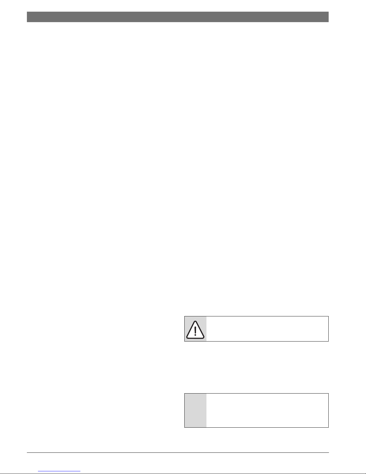
The Horizontal unit should be pitched approximately
1/4 inch towards the drain in both directions, to
facilitate condensate removal.
(see figure # 8)
Figure # 8 Pitched Unit
8 733 905 683 (2016/09)LV Heat Pump Series
10 | Installation LV Heat Pump Series
Step 7-Pipe Connections
Depending on the application there are 3 types of WSHP
piping systems to choose from: water loop, ground
water-and ground loop.
All WSHP units use female pipe thread fittings for water
connections. When making piping connections
considered the following:
• Insulation may be required on piping to avoid
condensation in the case where fluid in loop piping
operates at temperatures below dew point of
surrounding air.
• Piping systems that contains steel pipes or fittings
may be subject to galvanic corrosion. Dielectric
fittings may be used to isolate the steel parts of the
system to avoid galvanic corrosion.
Water Loop applications
Water loop applications usually include a number of
units plumbed to a common piping system. Maintenance
of any of the units can introduce air into the system.
Therefore, air elimination equipment comprises a major
portion of the mechanical room plumbing.
The flow rate is usually set between 2.25 and 3 GPM per
ton of cooling capacity. For proper maintenance and
servicing, pressure-temperature (P/T) ports are
necessary for temperature and flow verification.
In addition to complying with any applicable codes,
consider the following for system piping:
• Piping systems using water temperatures below
o
F require 1/2 inch closed cell insulation on all
50
piping surfaces to prevent pipe sweating.
• Avoid all plastic to metal threaded fittings due to the
potential for leaks.
• Teflon tape thread sealant is recommended to seal
pipe threads.
• Use Backup wrench. Do not overtighten
connections.
• Route piping to avoid service access areas to unit.
• Flush the piping system prior to operation to remove
dirt and foreign materials from the system.
Ground Loop Applications
Temperatures between 20ºand 110ºF and a cooling
capacity of 2.25 to 3 GPM of flow per ton is
recommended. In addition to complying with any
applicable codes, consider the following for system
piping:
• Limit piping materials to only polyethylene fusion in
the buried sections of the loop.
• Do not use galvanized or steel fittings at anytime
due to corrosion.
• Avoid all plastic to metal threaded fittings due to the
potential for leaks. Use a flange fitted substitute.
• Do not overtighten connections.
• Route piping to avoid service access areas to unit.
• Use pressure-temperature (P/T) plugs to measure
flow and pressure drop.
Step 8 Wire Field Power Supply
High Voltage
All field-installed wiring must comply with the National
Electric Code as well as all applicable local codes. Refer
to the unit electrical data on the unit nameplate for wire
and branch circuit protection sizing. Supply power
voltage and phasing should match the required voltage
and phasing shown on the unit nameplate. Operating the
unit below the minimum voltage, above the maximum
voltage or with incorrect phasing can result in poor
system performance or damage to the heat pump. All
field wiring should be installed by qualified and trained
personnel. Refer to the unit wiring diagram for field
connection requirements.
Power wiring to the heat pump should be enclosed in
flexible conduit to minimize the transmission of
vibration from the unit cabinet to the building.
For heat pumps with unit mounted disconnect switches,
field power should be connected to the marked
terminals on the disconnect switch. For heat pumps
without unit-mounted disconnect switches (except for
460-volt units noted below and units with dual power
supply), power is connected to the line (L) side of the
compressor contactor and the ground lug in the unit
electrical box.
Units with Dual Power Supplies
For models with dual power supplies, one power supply
feeds the compressor and a second power supply feeds
the unit fan motor and control circuit. The compressor
power supply should be connected to the line (L) side of
the compressor contactor. The fan motor and control
circuit power supply meets the voltage, amperage and
phase requirements of its load. Refer to the unit name
plates for requirements.
460-V Models with Constant Airflow Motors
The 460-V heat pumps with the constant airflow motor
option require a properly sized neutral wire with the
power supply wiring in addition to the three high voltage
wires and the ground wire. These units employ a 265-V
motor that requires power from one phase of the 460-V
supply and the neutral wire.
CAUTION: The unit ground wire should
never be used as a neutral wire
Transformer Settings for 208/230-V Units
As a factory built, all 208/230-V operation unless the
wire for 208-v option is ordered. For Job sites with a
208-V power supply, the primary leads on the unit
transformer will need to be changed from 240-V to 208V. Refer to the unit wiring diagram for details.
NOTICE: All High voltage connections must
be torqued as specified on contactor
specifications to avoid the risk of
overheating
LV Heat Pump Series8 733 944 336 (2016/09) Subject to change without prior notice
Installation | 11LV Heat Pump Series
Low Voltage
For heat pumps with PSC or constant torque fan motors,
all thermostat wiring is connected to a terminal block
located in the unit electrical box. For heat pumps with a
constant airflow fan motor thermostat wiring is
connected to a removal terminal strip located on the
ECM (Electronically Commutated Motor) control board
located in the electrical box. Refer to the unit wiring
diagram for connection details.
CAUTION: Never route control wiring
through the same conduit as power supply
wiring.
Unless provided with DDC controls, the unit heat pump
can be controlled by most commonly available singlestage heat pump thermostats. Note that the reversing
valve on the unit is energized when the unit is in the
cooling mode. Thermostats should be located on an
interior wall away from supply ducts. Avoid locations
subject to direct sunlight, drafts, external walls.
Thermostat wiring should be 18AWG (American Wire
Gage). refer to the installation instructions of the
thermostats for further details.
NOTICE: Exceptionally long runs of
thermostat wire should be avoided to
prevent voltage drops in the control circuit.
See Table #1 and #2 for recommended
length
Unit heat pumps are supplied with a 50VA control
transformer as a standard. Models with DDC, hot gas
reheat or an economizer are supplied with a 75 VA
transformer. The 75 VA and 100 VA transformers are
available as optional components for most models (size
018 and larger for 100 VA). The VA capacity of the
transformer should be considered when connecting low
voltage accessories to the heat pump such as
thermostats or solenoid valves. Table # 3 shows the VA
draw of factory mounted components in the low voltage
heat pump. The total VA draw of the heat pump internal
components plus attached accessories must be lower
than the VA capacity of the unit control transformer.
NOTICE: Exceeding the transformer
capacity can result in low control voltage,
erratic unit operation or damage to the heat
pump.
Thermostat to HVAC Equipment
The thermostat may not function properly if the total
resistance of any of the thermostat to HVAC equipment
wires exceeds 2.5 ohms. To ensure that wire length does
not cause excess resistance, refer to Table # 1and
ensure that the wires from the thermostat to the HVAC
equipment are not too long.
Table 1: Copper
wire size
22 AWG (0.33mm 2)
20 AWG (0.50mm 2)
18 AWG (0.75mm 2)
Maximum recommended
wire length
150 ft (46m)
240 FT (73m)
385 FT (117m)
Remote Sensor to Programmable Thermostat
Because remote temperature sensors measure
resistance, very long cable runs can cause slight errors
in the measurement. For the highest temperature
reading accuracy, avoid exceeding the maximum
recommended wire lengths show in Table # 2.
Table 2: Copper
wire size
22 AWG (0.33mm 2)
20 AWG (0.50mm 2)
18 AWG (0.75mm2)
Maximum recommended
remote sensor wire length
1000 ft (300m)
1500 FT (450m)
2500 FT (750m)
Table 3: Low Voltage VA Draw
STANDARD
CONSTRUCTION
Component VA Component VA Component VA
Blower Relay
(PSC motors
only)
Reversing
Valve
Solenoid
Compressor
Contactor
UPM Board 2
Total VA draw 22-26 Total VA
6-7 Total from
8-9 Additional
6-8 Hot Gas
HOT GAS REHEAT
OR ECONOMIZER
‘Standard’
Control
Relays
Reheat
Solenoid
draw
22-26 Monitor Relay
12-14 Internal 2
8-9 LED
42-49
OPTIONAL
COMPONENTS
(VA draw per
relay)
Way
Motorized
Valve
Annunciator
6-7
7
1
8 733 905 683 (2016/09)LV Heat Pump Series
12 | Installation LV Heat Pump Series
10
1
27
8
9
5
11
46
3
1
2
3
4
5
6
7
9
10
11
1213
17
14
15
16
8
Step 9- Wire Field Controls
Units Controls ECM-UPM
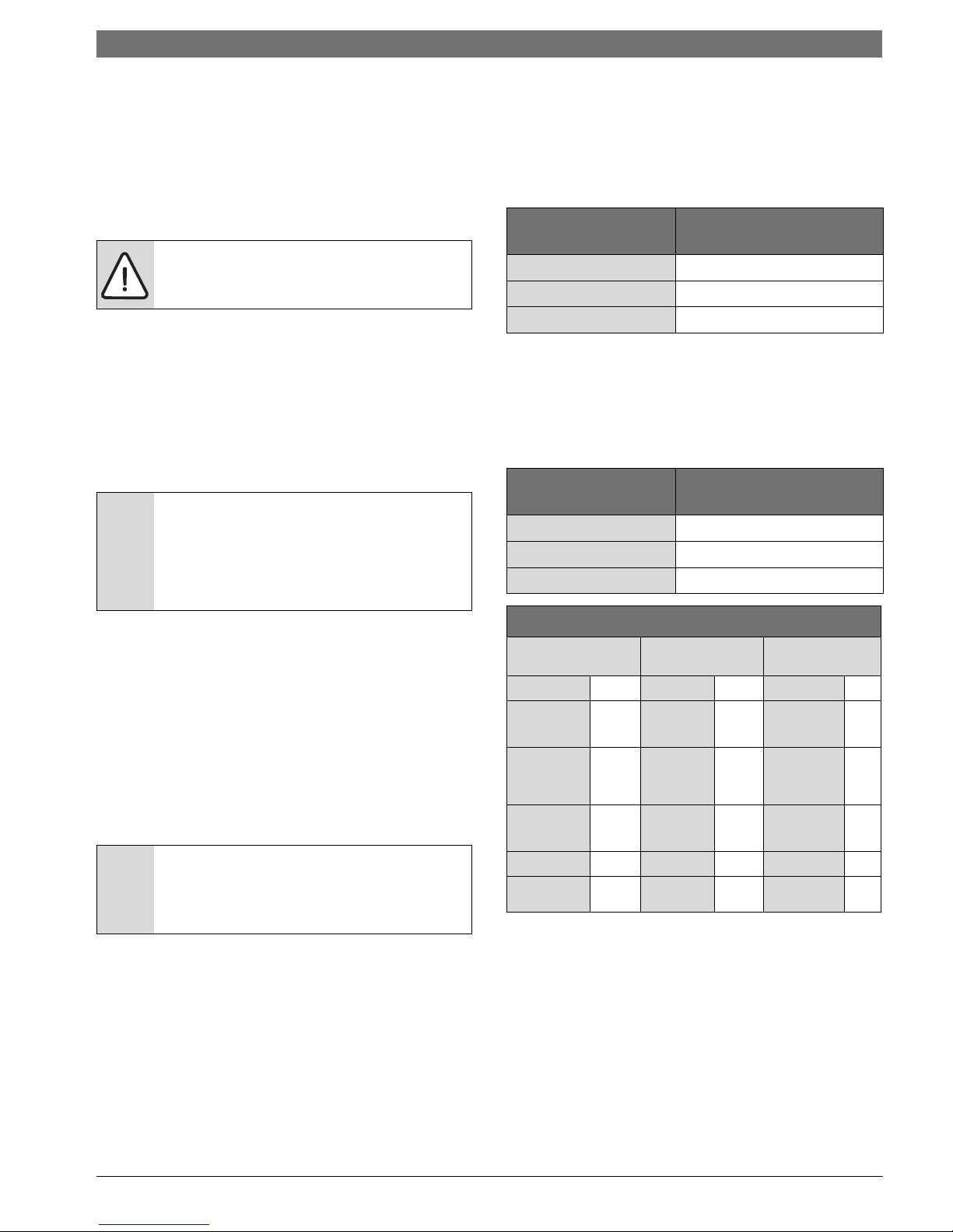
ECM Interface Board
Thermostat wiring is connected to the 10 pin screw type
terminal block on the lower center portion of the ECM
Interface Board. In addition to providing a connecting
point for thermostat wiring, the interface board also
translates thermostat inputs into control commands for
the Electronic Commutated Motor (ECM) DC fan motor
and displays an LED indication of operating status. The
thermostat connections and their functions are as
shown in figure # 9
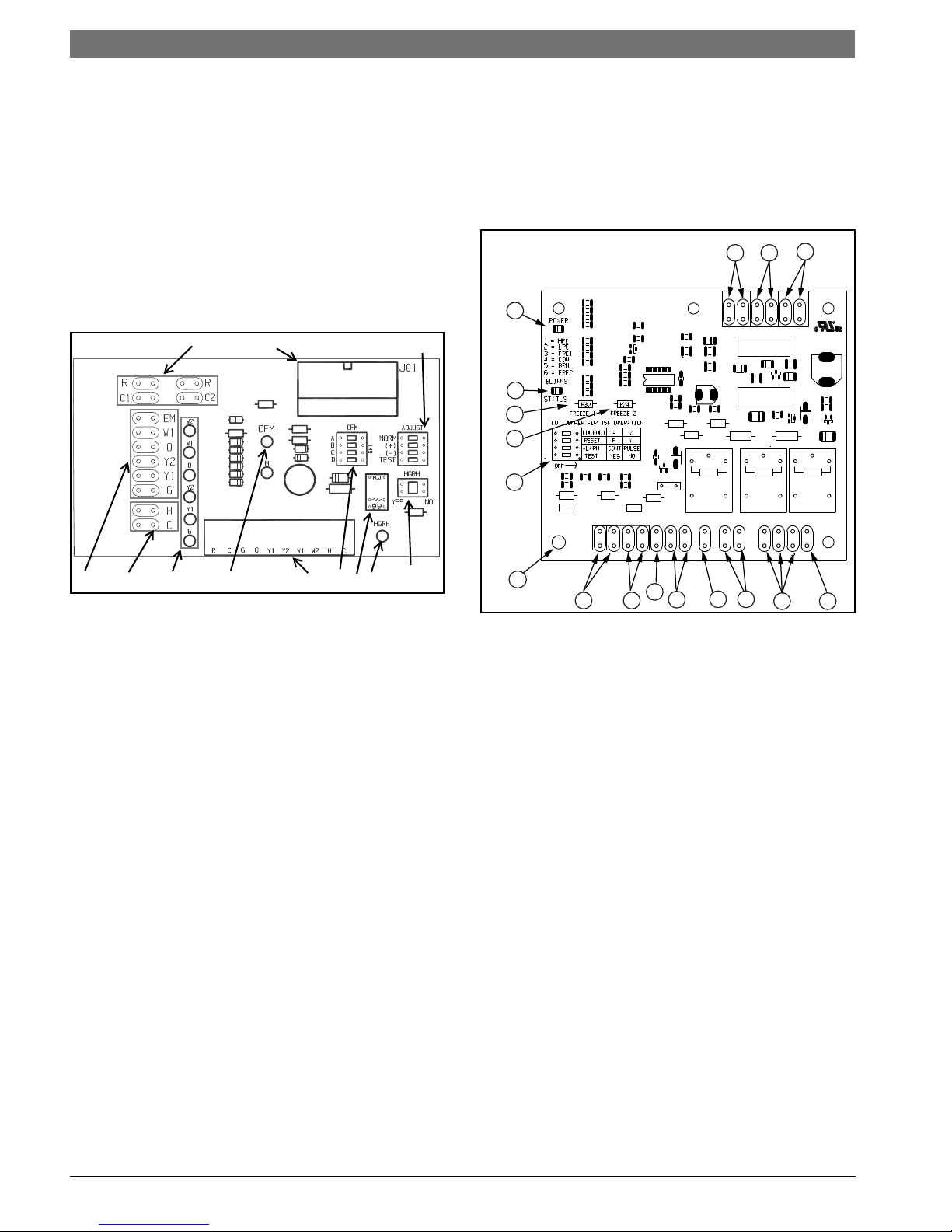
Safety devices and the UPM control
Each unit is factory provided with a UPM board
controller that controls the compressor operation and
monitors the safety.
If the unit is being connected to a thermostat with a
malfunction light, this connection is made at the unit
malfunction output or relay.
Figure # 9
[1] Motor harness plug
[2] Blower CFM adjustment
[3] Motor settings
[4] Dehumidification indication
[5] Thermostat contact inputs
[6] CFM count indicator
[7] Thermostat input status indication
[8] Reheat digital outputs
[9] Thermostat outputs
[10] 24 VAC
[11] Hot gas Re-heat enable switch
Figure # 10
[1] Board Power Indicator
[2] UPM Status LED Indicator
[3] Water Coil Freeze Protection Temperature Selection
[4] Air Coil Freeze Protection Temperature Selection
[5] UPM Board Settings
[6] Water Coil Freeze Connection
[7] Air Coil Freeze Connection
[8] LED Unit Display Connection
[9] 24VAC Power Input
[10] Compressor Contact Output
[11] High Pressure Switch Connection
[12] Call for Compressor Y1
[13] Low Pressure Switch Connection
[14] 24VAC Power Common
[15] Condensate Overflow Sensor
[16] Dry Contact
[17] UPM Ground Standoff
LV Heat Pump Series8 733 944 336 (2016/09) Subject to change without prior notice
Safety features includes the following:
• High pressure switch located in the refrigerant
discharge line and wired across the HPC terminals
on the complete UPM board
• Low pressure switch located in the unit suction line
and wired across terminals LPC1 and LPC2 on the
complete UPM Board
• Complete UPM board dry contacts are normally
open (NO).
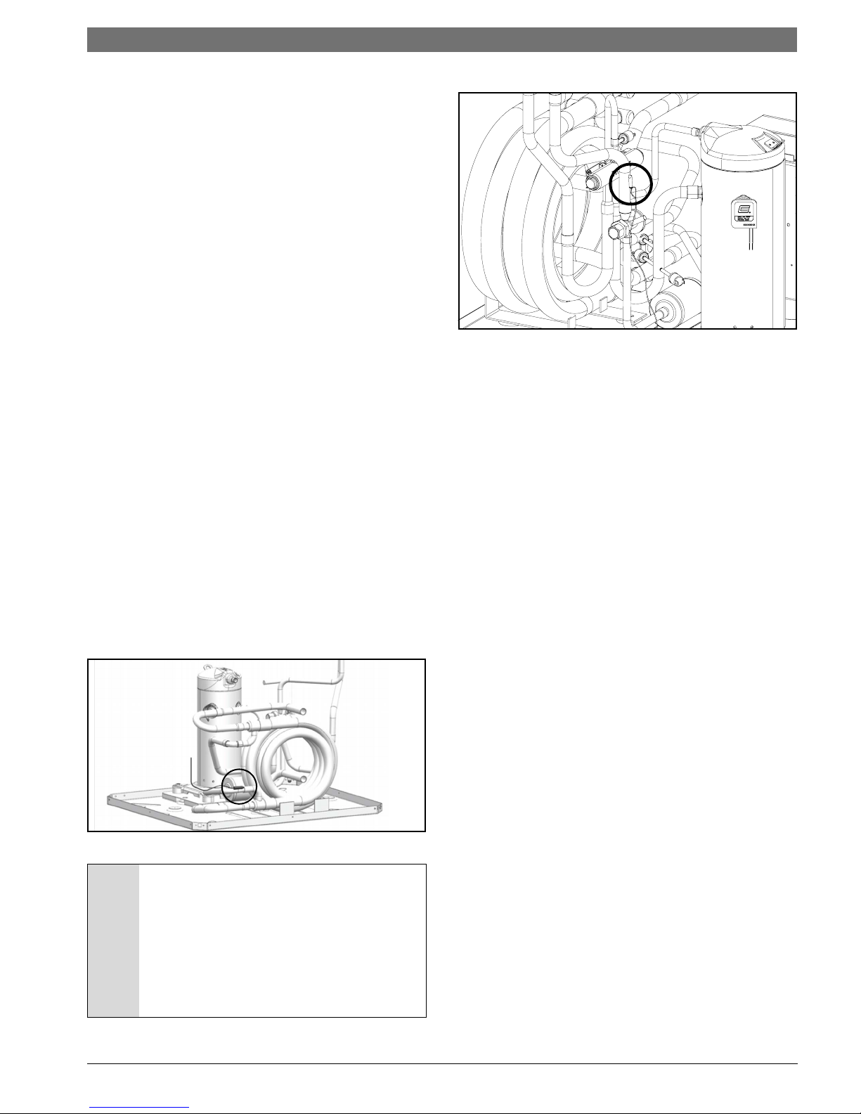
• Water side freeze protection sensor, mounted close
to condensing water coil, monitors refrigerant
temperature between condensing water coil and
thermal expansion valve. If temperature drops
below or remains at freeze limit trip for 30 seconds,
the controller will shut down the compressor and
enter a soft lockout condition. The default freeze
limit trip is 26°F, however this can be changed to
°
F by cutting the R30 or Freeze1 resistor located
15
on top of DIP switch SW1. For resistor location. If
unit is employing a fresh water system (no antifreeze protection), it is extremely important to have
the Freeze 1 R30 resistor set to 26
°
F in order to shut
down the unit at the appropriate leaving water
temperature and protect heat pump from freezing if
a freeze sensor is included.
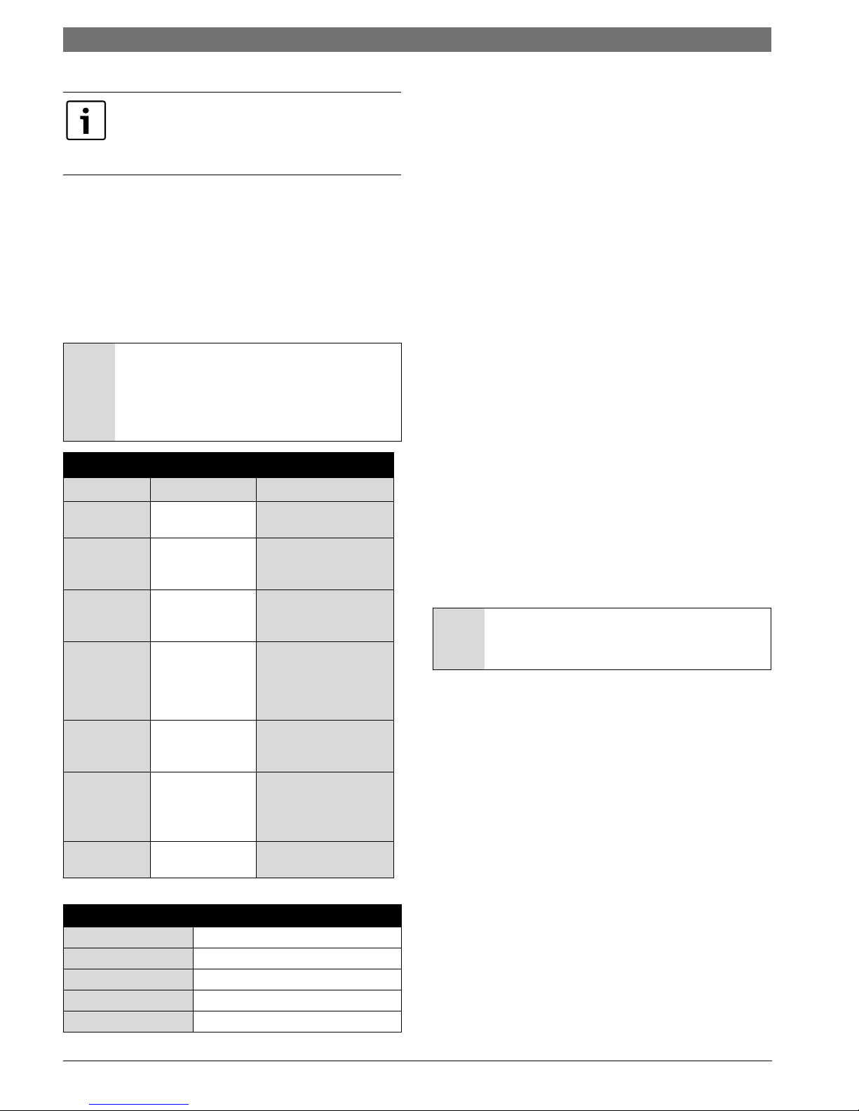
• Evaporator freeze sensor, mounted between the
thermal expansion device and the evaporator,
monitors refrigerant temperature between the
evaporator coil and thermal expansion valve. If
temperature drops below or remains at freeze limit
trip for 30 seconds, the controller will shutdown the
compressor and enter into a soft lockout condition.
The default freeze limit trip is 26
°
F See Figure # 10
• The condensate overflow protection sensor is
located in the drain pan of the unit and connected to
the COND terminal on the complete UPM board.
Figure # 11 Water side Freeze Protection Sensor
NOTICE: If unit is employing a fresh water
system (no anti-freeze protection), it is
extremely important to have the Freeze1
°
R30 resistor set to 26
F in order to
shutdown the unit at the appropriate
leaving-water temperature and protect your
heat pump from freezing if a freeze sensor is
included.
Installation | 13LV Heat Pump Series
Figure # 12
The UPM Board includes the following features:
• ANTI-SHORT CYCLE TIMER: 5 minute delay on
break timer to prevent compressor short cycling.
• RANDOM START: Each controller has a unique
random start delay ranging from 270 to 300 seconds
on initial power up to reduce the chance of multiple
units simultaneously starting at the same time after
power up or after a power interruption, thus
avoiding creating large electrical spike.
• LOW PRESSURE BYPASS TIMER: If the compressor
is running and the low pressure switch opens, the
controller will keep the compressor ON for 120
seconds. After 2 minutes if the low pressure switch
remains open, the controllers will shutdown the
compressor and enter a soft lockout. The
compressor will not be energized until the low
pressure switch closes and the anti-short cycle time
delay expires. if the low pressure switch opens 2-4
times in 1 hour, the unit will enter a hard lockout
power to the unit would need to be reset.
• BROWNOUT/SURGE/POWER INTERRUPTION: The
brownout protection in the UPM board will shut
down the compressor if the incoming power falls
below 18 VAC. The compressor will remain OFF until
the voltage is above 18 VAC and ANTI-SHORT CYCLE
TIMER (300 seconds) times out. The unit will not go
into a hard lockout.
• MALFUNCTION OUTPUT: Alarm output is normally
open (NO) dry contact. If pulse is selected the alarm
output will be pulsed. The fault output will depend
on the on the dip switch setting for “ALARM”. If it is
set to “CONST”, a constant signal will be produced
to indicate a fault and the unit requires inspection to
determine the type of fault. If is set to “PULSE”, a
pulse signal is produced and a fault code is detected
by a remote device indicating the fault. See LED
fault indication for blink code explanation. The
remote device must have a malfunction detection
capability when the UPM board is set to “PULSE”.
8 733 905 683 (2016/09)LV Heat Pump Series
14 | Installation LV Heat Pump Series
If 24 VAC output is needed. R must be wired to
ALR-COM terminal; 24 VAC will be available to the
ALR-OUT terminal when the unit is in the alarm
condition.
• DISPLAY OUTPUT: The display output is a pulse
output connected to the Unit Diagnostics Display
(UDD) and it pulses 24VAC when the unit is in an
lockout alarm condition.
• TEST DIP SWITCH: A test dip switch is provided to
reduce all time delays settings to 10 seconds during
troubleshooting or verification of unit operation. In
test mode the fault LED will flash 5 times in cooling
or 3 times in heating for five minutes.
NOTICE: Operation of unit in test mode can
lead to accelerated wear and premature
failure of components. The “TEST” switch
must be set back to “NO” after
troubleshooting/servicing.
Table 4: UPM Fault Blink Codes
LED Blinks Fault Fault Criteria
All fault conditions
None None
1
High Pressure
2
3
4Condensate
5 Air Coil Freeze
6Brown Out
Low Pressure
Water Coil
Freeze
Condition
Overflow
Condition
UPM Board Factory Default Settings
TEMP 26°F
LOCKOUT 2
RESET Y
ALARM PULSE
TEST NO
nominal
Refrigerant discharge
pressure has
exceeded 600 PSIG
Refrigerant suction
pressure has fallen
below 40 PSIG
Refrigerant
temperature to the
water coil has fallen
below 26°F for 30
seconds
Condensate levels in
the unit drain pan are
too high
Refrigerant
temperature to the air
coil has fallen below
26°F for 30 seconds
Control voltage has
fallen below 18 VAC
Freeze Sensor
°
The default setting for the freeze limit trip is 26
F
(sensor number 1); however this can be changed to 15°F
by cutting the R30 resistor located on top of the DIP
switch SW1, freeze limit trip should only be changed to
15°F when a closed loop system with appropriate
antifreeze mixture is used.Since freeze sensor 2 is
dedicated to monitor the evaporator coil it is
recommended to leave the factory default setting on the
board. The complete UPM controller will constantly
monitor the refrigerant temperature with the sensor
mounted close to the condensing water coil between the
thermal expansion valve and water coil. If temperature
drops below or remains at the freeze limits for 30
seconds. The controller will shut the compressor down
and enter into a soft lockout condition. Both the status
LED and the alarm contact will be active. The LED will
flash three times the code associated with this alarm
condition. If this alarm occurs 2 times (or 4 if DIP switch
is set to 4) within an hour the complete UPM controller
will enter into a hard lockout condition. It will constantly
monitor the refrigerant temperature with the sensor
mounted close to the evaporator between the thermal
expansion valve and evaporator coil as shown in figure #
11
If temperature drops below or remains at the freeze limit
trip for 30 seconds, the controller will shut the
compressor down and enter into a soft lockout
condition. Both the status LED and the alarm contact
will be active. The LED will flash three times the code
associated with this alarm condition. If this alarm occurs
2 times (or 4 if DIP switch is set to 4 within an hour the
controller will enter into a hard lockout condition.
NOTICE: It is recommended to have a flow
switch to prevent the unit from running if
water flow is lost.
Intelligent Reset
If a fault condition is initiated, the 5 minute delay on
break time period is initiated and the unit will restart
after this delays expire and if the fault condition has
been resolved. During this period the fault LED will
indicate the cause of the fault. If the fault condition still
exists or occurs 2 or 4 times (depending on 2 or 4
settings for lockout dip switch) before 60 minutes, the
unit will go into a hard lockout and requires a manual
lockout reset. A single condensate overflow fault will
cause the unit to go into hard lockout immediately, and
will require a manual lockout reset.
Lockout Reset
A hard lockout can be reset by turning the unit
thermostat off and then back on. When the RESET dip
switch is set to “Y” or by shutting off power at the circuit
breaker when the RESET DIP switch is set to “R”.
LV Heat Pump Series8 733 944 336 (2016/09) Subject to change without prior notice

THERMOSTAT OPTIONS
Y1 First Stage Compressor Operation
GFan
O Reversing Valve (energized in cooling)
W1 Auxiliary Electric Heat (runs in conjunction
with compressor)
Pre-Start-Up | 15LV Heat Pump Series
Air coil
To obtain maximum performance, clean the air coil
before starting the unit. A 10% solution of dishwasher
detergent and water is recommended for both sides of
the coil. Rinse thoroughly with water.
START-UP
Use the procedure below to initiate a proper start-up
NC Transformer 24 VAC Common (extra
connection)
C1 Transformer 24 VAC Common (primary
connection)
R Transformer 24 VAC Hot
H Dehumidification Mode
UPM DIP SWITCH DEFAULT POSITION
lockout 42
reset
alarm
test
RY
Cont pulse
yes no
PRE-START-UP
System Checkout
After completing the installation, and before energizing
the unit, the following system checks should be made
prior to initial startup:
1. Verify that the supply voltage to the heat pump is in
accordance with the nameplate ratings.
2. Make sure that all electrical connections are tight
and secure.
3. Check the electrical fusing and wiring for the correct
size.
4. Verify that the low voltage wiring between the
thermostat and the unit is correct.
5. Verify that the water piping is complete and correct.
6. Check that the water flow is correct, and adjust if
necessary.
7. Check the blower for free rotation, and that it is
secured to the shaft.
8. Verify that vibration isolation has been provided.
9. Unit is serviceable. Be certain that all access panels
are secured in place.
10. Verify that the blower support has been removed.
11. Verify that duct work has been properly fastened to
supply and return duct collars.
12. Make sure return air filters are positioned correctly
in the filter rack if removed during installation.
NOTICE: This equipment is designed for
indoor installation only
Operating Limits
Environment
This equipment is designed for indoor installation only.
Extreme variations in temperature, humidity and
corrosive water or air will adversely affect the unit
performance, reliability and service life.
Power Supply
A voltage variation of
voltage is acceptable.
Unit Starting Conditions
Minimum ambient temperature for heating operation is
45°F. Minimum entering air for heating is 40°F. Minimum
entering water temperature for heating with standard
range units is 50°F and for extended range units is 20°F.
Air and water flow rates must be within the cataloged
range.
These operating limits are not suitable for
continuous operating conditions. Assume
that such start up conditions are for the
purpose of bringing the building space up to
occupancy temperature.
WARNING: When the disconnect switch is
closed, high voltage is present in some
areas of the electrical panel. Exercise
caution when working with the energized
equipment.
1. Restore power to system.
2. Turn thermostat fan position to ON. Blower should
start.
3. Balance airflow at registers.
4. Adjust all valves to the full open position and turn on
the line power to the heat pump unit.
5. Operate unit in the cooling cycle first, then the
heating cycle. for unit operating limits. Allow 15
minutes between cooling and heating tests for
pressure to equalize.
± 10% of nameplate utilization
8 733 905 683 (2016/09)LV Heat Pump Series

16 | Start-Up LV Heat Pump Series
Two factors determine the operating limits of a unit:
entering air temperature and water temperature.
Whenever any of these factors are at a minimum or
maximum level, the other two factors must be at a
normal level to ensure proper unit operation.
Scroll Compressor Rotation (4 and 5
Tons only)
It is important to be certain that the compressor is
rotating in the proper direction. To determine whether
or not compressor is rotating in the proper direction see
as follows:
1. Connect services gases to suction and discharge
pressure fittings.
2. Energize the compressor.
3. The suction pressure should drop and the discharge
pressure should rise, as is normal on any start up.
If the suction pressure does not drop and the discharge
pressure does not rise to normal levels:
1. Turn off power to the unit. Install disconnect tag.
2. Reverse any two of the unit power leads.
3. Reapply power to the unit and verify pressures are
correct.
The suction and discharge pressure levels should now
move to their normal start-up levels.
When the compressor is rotating in the wrong direction,
the unit makes more noise and does not provide cooling.
After a few minutes of reverse operation, the scroll
compressor internal overload protection will open, thus
activating the unit lockout. This requires a manual reset.
To reset, turn the thermostat on and then off.
There is a 5 minute time delay before the compressor
will start.
LV Heat Pump Series8 733 944 336 (2016/09) Subject to change without prior notice

Sequence Of Operation
CC
LOCKOUT CAN BE SET
TO 4 VIA DIP SWITCH
BLINK CODE ON STATUS LED
SOFT LOCKOUT
RECORD ALARM
START COUNTER (IF APPLICABLE)
CC OUTPUT = ON
NO
YES
LPC
=CLOSED
FRZ >TEMP
LIMIT
Y1 = ON
TIME > 30
SEC
CON > 0
POWER/ SWITCHES/SENSOR
STATUS CHECK
START
TIMER
NO
YES
NO
YES
NO
YES
T > ASC OR
RS SEC
YES
NO
NO
YES
START
ANTI SHORT CYCLE
INITIAL
POWER UP
YES
NO
START
RANDOM START UP
START
COUNTER
NEEDED?
YES
COUNT = 2
OR
COUNT = 4
BLINK CODE ON STATUS LED
DISPLAY OUTPUT = PULSE
ALR OUTPUT = ON/PULSE
NO
YES
HARD
LOCKOUT?
CC OUTPUT = OFF
V > 18VAC
NO
YES
YES
NO
BLINK CODE
ON STATUS LED
NO
RESET ON
Y
CLEAR FAULTS
R = 24VAC
NO
YES
NO
YES
NO
YES
HPC =
CLOSED
RESET ON R
CC OUPUT=
ON
NO
YES
TIME >
120 SEC
START
TIMER
NO
YES
CNT = CNT+1
Start-Up | 17LV Heat Pump Series
Figure # 13
8 733 905 683 (2016/09)LV Heat Pump Series

18 | Start-Up LV Heat Pump Series
Figure # 14
LV Heat Pump Series8 733 944 336 (2016/09) Subject to change without prior notice
Unit Start Up Cooling Mode
1. Adjust the unit thermostat to the warmest position.
Slowly reduce the thermostat position until the
compressor activates.
2. Check for cool air delivery at unit grille a few
minutes after the unit has begun to operate.
3. Verify that the compressor is ON and that the water
flow rate is correct by measuring pressure drop
through the heat exchanger using P/T plugs. Check
elevation and cleanliness of the condensate lines;
any dripping could be a sign of a blocked line. Be
sure the condensate trap includes a water seal.
4. Check the temperature of both supply and
discharge water.
5. Check air temperature drop across the coil when
compressor is operating. Air temperature drop
should be between 15
o
and 25oF.
Unit Start Up Heating Mode
Oper
1. Turn thermostat to lowest setting and set
2. Slowly turn the thermostat to a higher temperature
3. Check for warm air delivery at the unit grille within a
4. Check the temperature of both supply and
5. Once the unit has begun to run, check for warm air
6. Check air temperature rise across the coil when
7. Check for vibration, noise and water leaks.
Operate the unit in heating cycle after checking the
cooling cycle. Allow 5 minutes between tests for the
pressure or reversing valve to equalize.
thermostat switch to HEAT position.
until the compressor activates.
few minutes after the unit has begun to operate.
discharge water. If temperature is within range,
proceed. If temperature is outside the range, check
the heating refrigerant pressures.
delivery at the unit grille.
compressor is operating. Air temperature rise
should be between 20
°
F and 30°F after 15 minutes
load.
Start-Up | 19LV Heat Pump Series
WARNING: Open the disconnect switch and
secure it in an open position before flushing
the system.
Flushing
Once the piping is complete, units require final purging
and loop charging. A flush cart pump of at least 1.5 hp is
needed to achieve adequate flow velocity in the loop to
purge air and dirt particles from the loop. Flush the loop
to purge air and dirt particles from the loop. Flush the
loop in both directions with a high volume of water at a
high velocity.
Follow the steps below to properly flush the loop:
1. Verify that the power is off.
2. Fill loop with water from the hose through flush cart
before using flush cart pump to ensure an even fill.
Do not allow the water level in the flush cart tank to
drop below the pump inlet line to prevent air from
filling the line.
3. Maintain a fluid level in the tank above the return tee
to avoid entering back into the fluid.
4. Shutting off the return valve that connects into the
flush cart reservoir it will allow 50 psig surges to
help purge air pockets. This maintains the pump at
50 psig.
5. To purge, keep the pump at 50 psig until maximum
pumping pressure is reached.
6. Open the return valve to send a pressure surge
through the loop to purge any air pockets in the
piping system.
7. A noticeable drop in fluid level will be seen in the
flush cart tank. This is the only indication of air in the
loop.
If air is purged from the system while using a 10 inch
PVC flush tank, the level drop will only be 1 to 2
inches, since liquids are incompressible. If the level
drops more than this, flushing should continue since
air is still being compressed in the loop. If level is
less than 1 to 2 inches, reverse the flow.
Flow Regulation
Flow regulation can be accomplished by two methods.
Most water control valves have a flow adjustment built
into the valve. By measuring the pressure drop through
the unit heat exchanger, the flow rate can be
determined. Adjust the water control valve until the
desired flow is achieved. Since the pressure constantly
varies, two pressure gages may be needed in some
applications.
An alternative method is to install a flow control device.
These devices are typically an orifice of plastic material
designed to allow a specified flow rate that are mounted
on the outlet of the water control valve. Occasionally
these valves produce a flow noise that can be reduced
by applying some back pressure. To accomplish this,
slightly close the leaving isolation valve of the well water
setup.
8. Repeat this procedure until all air is purged.
9. Restore power.
Antifreeze may be added before, during or after the
flushing process. However, depending on when it is
added in the process, it can be wasted. refer to the
Antifreeze section for more detail.
Loop static pressure will fluctuate with the seasons.
Pressures will be higher in the winter months than
during the warmer months. this fluctuation is normal
and should be considered when charging the system
initially. Run the unit in either heating or cooling for
several minutes to condition the loop to a homogenous
temperature.
When complete, perform a final flush and pressurize the
loop to a static pressure of 40 to 50 psig for winter
months or 15 to 20 psig for summer months.
8 733 905 683 (2016/09)LV Heat Pump Series

20 | Application Considerations LV Heat Pump Series
After pressurization, be sure to remove the plug from the
end of the loop pump motor to allow trapped air to be
discharged and to ensure the motor housing has been
flooded. Be sure the loop flow center provides adequate
flow through the unit by checking pressure drop across
the heat exchanger.
Antifreeze
In areas where entering loop temperatures drop below
40°F or where piping will be routed through areas
subject to freezing, antifreeze is needed.
Alcohols and glycols are commonly used as antifreeze
agents. Freeze protection should be maintained to 15
°
F
below the lowest expected entering loop temperature.
For example, if the lowest expected entering loop
temperature is 30°F, the leaving loop temperature would
be 22°F to 25°F. Therefore, the freeze protection should
be at 15
°
F (30°F-15°F=15°F).
NOTICE: All alcohols should be pre-mixed
and pumped from a reservoir outside the
building or introduced under water level to
avoid build up of fumes.
1. Flex Duct Connection.
2. Low Voltage Control Connection
Figure # 15
3. Vibration Pad
Antifreeze concentration should be checked from a well
mixed sample using a hydrometer to measure specific
gravity.
4. Ball Valves
5. Solenoid Valve Slow Closing
6. Condensate Drain Connection
7. Drain Valves
Freeze Protection Selection
The 26°F FP1 factory setting (water) should be used to
avoid freeze damage to the unit.
Once antifreeze is selected. the (FP1 jumper) should be
clipped on the control to select the low temperatures
(antifreeze 15°F) set point to avoid nuisance faults.
8. Hose Kits (optional)
9. Pressure Tank (optional)
10. P/T Ports (optional)
11. Line Voltage Connection
12. Electric Heater Line Voltage Disconnect
13. Unit Line Voltage Disconnect
APPLICATION CONSIDERATIONS
Well Water Systems
Copper is adequate for ground water that is not high in
mineral content. Should your well driller express
concerns regarding the quality of the well water
available or should any know hazards exists in your area,
we recommend proper testing to assure the well water
quality is suitable for use with water source equipment.
(See water quality table on page #21) in conditions
anticipating moderate scale formation or in brackish
water a cupro-nickel heat exchanger is recommended. In
well water applications water pressure must always be
maintained in the heat exchanger. This can be
accomplished with a control valve or a bladder type
expansion tank. When using a single water well to supply
both domestic water and the heat pump care must be
taken to ensure that the well can provide sufficient flow
for both. In well water applications a slow closing
solenoid valve must be used to prevent water hammer.
Solenoid valves should be connected across Y1 and C1
on the interface board for all. Make sure that the VA
draw of the valve does not exceed the contact rating of
the thermostat.
LV Heat Pump Series8 733 944 336 (2016/09) Subject to change without prior notice
 Loading...