


boschhheattingandcoo ling.com | 1
LV Model
Water Source Heat Pump
1/2 to 6 ton
The option-rich, water-to-air LV offers one of the smallest cabinets in the industry, making it a great choice for replacement and new construction projects.
LV |
UP TO |
UP TO |
16.9 |
5.3 |
|
MODEL |
EER |
COP |
|
GLHP |
WSHP |
|
|
|
Commercial Sales Catalog boschheatingandcooling.com
Subject to change without p rio notice
1 | LV Model | Commercial Geothermal Heat Pumps |
|
Table of Contents |
|
MODEL NOMENCLATURE.............................................. |
2 |
CERTIFIED PERFORMANCE DATA................................. |
2 |
FHP EQUIPMENT ............................................................ |
3 |
ADVANTAGES OF FHP’s TECHNOLOGY........................ |
3 |
LV MODEL 007-070 ......................................................... |
3 |
FEATURES, FUNCTIONS AND BENEFITS.................. |
3-5 |
Cabinet...................................................................... |
3 |
Quiet Operation ....................................................... |
4 |
Serviceability ........................................................... |
4 |
Unit Configurations................................................... |
4 |
Filter Racks and Options .......................................... |
4 |
Optional MERV-8 and -13 Filter................................. |
4 |
FAN MOTOR .................................................................... |
5 |
Permanent Split Capacitor Motors (PSC)................ |
5 |
ECM Constant Torque Motor (Optional).................. |
5 |
ECM Constant Airflow Motor ................................... |
5 |
Hanging Brackets...................................................... |
5 |
Water Connections ................................................... |
5 |
Two-Position Water Valve.......................................... |
5 |
Refrigerant Circuit .................................................... |
5 |
Evaporator Coil and DuoGuardTM ............................. |
6 |
Blower Housing......................................................... |
6 |
Unit Protection Module ......................................... |
6-7 |
UPM CONTROL BOARD FEATURES ........................... |
7-8 |
ADDITIONAL OPTIONS ................................................. |
8 |
Hot Gas Reheat........................................................ |
8 |
Hot Gas Reheat Control Options ............................. |
9 |
Special Considerations............................................. |
9 |
Low Temperature Well Water ................................... |
9 |
Indoor Pool Dehumidifying During Winter Months..... |
9 |
Sequence of Operation - Modulating |
|
Hot Gas Reheat (MHGRH)........................................ |
9 |
Hot Gas Bypass......................................................... |
9 |
Psychrometric Chart............................................... |
10 |
DDC Controls ................................................................ |
10 |
DDC Room Sensors................................................ |
10 |
DDC Zone Sensors .................................................. |
11 |
Waterside Economizer Common Waterside |
|
Economizer Applications......................................... |
11 |
Fluid Flow ................................................................ |
11 |
Aquastat.................................................................. |
12 |
Air Side Pressure Drop ........................................... |
12 |
Fluid Differential Pressure Switch.......................... |
12 |
Energy Management Switch (EMS) ....................... |
12 |
OTHER OPTIONS .......................................................... |
13 |
ACCESSORIES ............................................................. |
13 |
Thermostats............................................................ |
13 |
Hose Kits................................................................. |
13 |
UNIT CONFIGURATION DIAGRAMS ........................... |
14 |
SYSTEMS ....................................................................... |
15 |
Water Source Cooling Tower/Boiler Systems........ |
15 |
Geothermal Systems .............................................. |
15 |
Earth Coupling Options...................................... |
15-16 |
Vertical Ground Loop System................................. |
16 |
Horizontal Ground Loop System............................ |
16 |
Surface Water, Lake or Pond System...................... |
17 |
Well Water System................................................... |
17 |
TYPICAL HEAT PUMP OPERATION.............................. |
17 |
Cooling Mode........................................................... |
17 |
Heating Mode........................................................... |
17 |
TYPICAL UNIT INSTALLATION ..................................... |
18 |
Water-to-Air Heat Pump Cycle - Cooling................. |
18 |
Water-to-Air Heat Pump Cycle - Heating................. |
18 |
Unit Location........................................................... |
18 |
Vertical Unit Installation ......................................... |
18 |
Horizontal Unit Installation .................................... |
19 |
Ductwork & Sound Attenuation Considerations.... 19 |
|
Piping ...................................................................... |
20 |
Condensate Drain Piping........................................ |
20 |
Operating Limits – Cooling & Heating .............. |
20-21 |
EQUIPMENT SELECTION.............................................. |
21 |
ANTIFREEZE CORRECTION DATA ............................... |
22 |
WATERSIDE PRESSURE DROP.................................... |
22 |
CAPACITY DATA ..................................................... |
23-35 |
LV007 (300 CFM).................................................... |
23 |
LV009 (350 CFM) ................................................... |
24 |
LV012 (400 CFM) .................................................... |
25 |
LV015 (500 CFM).................................................... |
26 |
LV018 (650 CFM).................................................... |
27 |
LV024 (850 CFM).................................................... |
28 |
LV030 (950 CFM) ................................................... |
29 |
LV036 (1200 CFM) ................................................. |
30 |
LV041 (1150 CFM) ................................................... |
31 |
LV042 (1500 CFM) .................................................. |
32 |
LV048 (1600 CFM).................................................. |
33 |
LV060 (2000 CFM) ................................................. |
34 |
LV070 (2200 CFM).................................................. |
35 |
UNIT ELECTRICAL DATA.............................................. |
36 |
Standard Blower Motor .......................................... |
36 |
ECM Constant Torque ............................................ |
37 |
ECM Constant Airflow (Variable Speed)............... |
38 |
BLOWER PERFORMANCE CFM.................................. |
39 |
Standard Blower Motor .......................................... |
39 |
ECM Constant Torque ........................................... |
40 |
ECM Constant Airflow (Variable Speed)................ |
41 |
PHYSICAL DATA ........................................................... |
42 |
HORIZONTAL CABINET CORNER WEIGHTS.............. |
43 |
VERTICAL UNIT DIMENSIONS .................................... |
44 |
HORIZONTAL UNIT DIMENSIONS............................... |
45 |
COUNTERFLOW UNIT DIMENSIONS.......................... |
46 |
GUIDE SPECIFICATION .......................................... |
47-50 |
Subject to change without prior notice.

boschheatingandcooling.com | 2
Model Nomenclature
|
|
LV |
036 |
1 |
VT |
C |
F |
L |
T |
P |
U |
A |
|
|
MODEL: |
|
|
|
|
|
|
|
|
|
REVISION LEVEL: |
||||
LV |
|
|
|
|
|
|
|
|
|
|
|
A |
- |
Current |
NOMINAL CAPACITY: |
|
|
|
|
|
|
|
|
|
AIR COIL OPTIONS: |
||||
007, 009, 012, 015, 018, |
|
|
|
|
|
|
|
|
U |
- |
Uncoated Air Coil |
|||
024, 030, 036, 041, 042, |
|
|
|
|
|
|
|
|
||||||
|
|
|
|
|
|
|
|
D |
- |
DuoGuard™ Air Coil |
||||
048, 060, 070 |
|
|
|
|
|
|
|
|
|
|||||
|
|
|
|
|
|
|
|
|
|
|
|
|||
VOLTAGE DESIGNATION: |
|
|
|
|
|
|
|
|
FAN/MOTOR OPTIONS: |
|||||
|
|
|
|
|
|
|
|
P |
- |
Standard PSC |
||||
0 |
- |
115/60/1 (LV012 only) |
|
|
|
|
|
|
|
|
||||
|
|
|
|
|
|
|
|
A |
- |
ECM Constant Airflow |
||||
1 |
- |
208/60/1 & 230/60/1 |
|
|
|
|
|
|
|
|
||||
|
|
|
|
|
|
|
|
T |
- |
ECM Constant Torque |
||||
2 |
- |
265/60/1 |
|
|
|
|
|
|
|
|
|
|||
|
|
|
|
|
|
|
|
|
|
|
|
|||
3 |
- |
208/60/3 & 230/60/3 |
|
|
|
|
|
|
|
|
DISCHARGE AIR CONFIGURATION: |
|||
4 |
- |
460/60/3 |
|
|
|
|
|
|
|
|
|
|||
|
|
|
|
|
|
|
|
|
T |
- |
Top |
|||
5 |
- |
575/60/3 |
|
|
|
|
|
|
|
|
|
|||
|
|
|
|
|
|
|
|
|
S |
- |
Straight |
|||
|
|
|
|
|
|
|
|
|
|
|
|
|||
CABINET CONFIGURATION: |
|
|
|
|
|
|
|
|
E |
- |
End |
|||
|
|
|
|
|
|
|
|
B |
- |
Bottom |
||||
VT |
- |
Vertical |
|
|
|
|
|
|
|
|
|
|||
|
|
|
|
|
|
|
|
|
|
|
|
|||
HZ |
- |
Horizontal |
|
|
|
|
|
|
|
|
|
RETURN AIR CONFIGURATION: |
||
CF |
- |
Counterflow (Downflow) |
|
|
|
|
|
|
|
|
||||
|
|
|
|
|
|
|
|
L |
- |
Left |
||||
|
|
|
|
|
|
|
|
|
|
|
|
|||
COAX OPTIONS: |
|
|
|
|
|
|
|
|
|
R |
- |
Right |
||
|
|
|
|
|
|
|
|
|
|
|
|
|||
C |
- |
Copper |
|
|
|
|
|
|
|
|
|
WATER CONNECTIONS: |
||
N |
- |
Cupro-Nickel |
|
|
|
|
|
|
|
|
|
|||
|
|
|
|
|
|
|
|
|
F |
- |
Front |
|||
|
|
|
|
|
|
|
|
|
|
|
|
|||
Certified Performance Data
|
|
|
|
|
AHRI/ANSI 13256-1 Performance Data |
|
|
|
|||||
|
|
|
|
|
|
|
Entering Water Temperatures |
|
|
|
|
||
|
Fluid Flow |
|
86˚F |
|
68˚F |
77˚F |
|
|
32˚F |
||||
Model |
|
|
Water Loop |
|
|
|
|
Ground Loop |
|
|
|||
Rate |
|
|
|
|
|
|
|
|
|||||
|
|
|
|
Capacity and Efficiency Data – PSC Motor (Standard) |
|
|
|
||||||
|
|
|
|
|
|
|
|
||||||
|
|
Cooling |
|
EER |
Heating |
|
COP |
Cooling |
|
EER |
Heating |
|
COP |
|
|
Capacity |
|
Capacity |
|
Capacity |
|
Capacity |
|
||||
|
|
|
(WLHP) |
|
(WLHP) |
|
(GLHP) |
|
(GLHP) |
||||
|
|
(WLHP) |
|
(WLHP) |
|
(GLHP) |
|
(GLHP) |
|
||||
|
|
|
|
|
|
|
|
|
|
||||
|
|
|
|
|
|
|
|
|
|
|
|
|
|
LV007 |
2.0 |
6,100 |
|
12.20 |
7,800 |
|
5.30 |
6,800 |
|
15.10 |
4,900 |
|
3.40 |
LV009 |
2.5 |
8,200 |
|
12.40 |
9,900 |
|
4.70 |
8,700 |
|
14.60 |
5,740 |
|
3.20 |
LV012 |
3 |
10,900 |
|
12.20 |
13,000 |
|
4.30 |
11,800 |
|
14.10 |
8,700 |
|
3.20 |
LV015 |
4 |
14,200 |
|
12.80 |
16,100 |
|
4.40 |
14,200 |
|
14.60 |
11,300 |
|
3.30 |
LV018 |
5.0 |
19,400 |
|
13.40 |
22,200 |
|
4.60 |
21,200 |
|
15.80 |
14,300 |
|
3.50 |
LV024 |
6 |
23,400 |
|
13.40 |
26,600 |
|
4.40 |
25,000 |
|
15.50 |
17,000 |
|
3.40 |
LV030 |
7 |
29,200 |
|
13.20 |
33,400 |
|
4.30 |
31,000 |
|
14.70 |
20,900 |
|
3.30 |
LV036 |
9 |
37,900 |
|
14.70 |
41,800 |
|
4.60 |
39,900 |
|
16.90 |
26,900 |
|
3.50 |
LV041 |
9 |
39,500 |
|
13.10 |
44,600 |
|
4.30 |
41,200 |
|
14.30 |
29,400 |
|
3.20 |
LV042 |
10 |
40,000 |
|
13.70 |
46,300 |
|
4.30 |
42,600 |
|
14.80 |
31,000 |
|
3.30 |
LV048 |
12 |
45,900 |
|
13.00 |
56,400 |
|
4.30 |
48,800 |
|
14.90 |
35,400 |
|
3.40 |
LV060 |
15 |
57,900 |
|
13.00 |
67,200 |
|
4.30 |
60,100 |
|
14.10 |
46,900 |
|
3.20 |
LV070 |
16 |
64,000 |
|
13.30 |
72,800 |
|
4.40 |
66,400 |
|
15.00 |
50,800 |
|
3.40 |
|
|
|
|
|
ECM Motor (Option) |
|
|
|
|
|
|
||
LV015 |
|
|
|
|
|
|
|
16.20 |
|
|
|||
4 |
13,700 |
|
13.90 |
15,500 |
|
4.40 |
14,400 |
|
10,700 |
|
3.30 |
||
LV018 |
5.0 |
19,700 |
|
14.40 |
21,900 |
|
4.80 |
21,500 |
|
15.90 |
14,100 |
|
3.70 |
LV024 |
6 |
23,800 |
|
14.50 |
26,200 |
|
4.60 |
25,400 |
|
16.80 |
16,700 |
|
3.60 |
LV030 |
7 |
30,000 |
|
15.00 |
32,800 |
|
4.60 |
31,600 |
|
17.50 |
20,400 |
|
3.40 |
LV036 |
9 |
38,200 |
|
15.40 |
41,400 |
|
4.70 |
40,200 |
|
17.70 |
26,500 |
|
3.60 |
LV041 |
9 |
40,500 |
|
13.60 |
43,700 |
|
4.40 |
42,200 |
|
15.90 |
28,500 |
|
3.60 |
LV042 |
10 |
40,900 |
|
14.10 |
45,300 |
|
4.40 |
43,500 |
|
16.30 |
30,100 |
|
3.50 |
LV048 |
12 |
46,800 |
|
14.20 |
55,600 |
|
4.50 |
49,600 |
|
16.30 |
34,600 |
|
3.60 |
LV060 |
15 |
59,000 |
|
14.30 |
66,400 |
|
4.30 |
61,100 |
|
16.40 |
46,200 |
|
3.30 |
LV070 |
16 |
65,200 |
|
14.60 |
71,800 |
|
4.60 |
67,600 |
|
16.60 |
50,000 |
|
3.50 |
Tabulated performance data is at noted water temperatures and entering air conditions of 80.6°F DB/66.2°F WB at AHRI/ANSI 13256-1 rated CFM with 1" disposable filter.
GLHP ratings require an extended range option. ECM motors can be either constant torque or constant CFM.
Subject to change without prior notice.
3 | LV Model | Commercial Geothermal Heat Pumps
FHP Equipment
Specializing in efficient green technology for commercial heating and cooling products. FHP products are one of the leading Geothermal and Water Source heat pumps in the market, which assures that you are buying a unit that you can trust. Bosch Thermotechnology Corp. is dedicated to providing highly efficient heating and cooling solutions to the private and public sectors.
Bosch Thermotechnology Corp. is always on the forefront of product development and innovative design to optimize the performance of FHP units.
Our products are designed and manufactured to the highest quality, reflecting the no-compromise standards for which FHP and Bosch are renowned in order to provide our customers with the highest level of satisfaction and comfort. The variety of options, energy efficiency, and uncompromising quality of all FHP products makes them the ideal choice for the commercial new construction market and the ease of designing into tight retrofit spaces of buildings.
Advantages of FHP Technology
Low installation costs
Lower operating costs
Flexibility and comfort
Energy efficiency
Space savings
Superior quality
Quiet operation
LV Model 007 - 070
13 Models from 1/2 through 6 tons
Horizontal, Vertical, and Counterflow Configurations*
The LV Model is a cost-effective, single stage water source heat pump designed for commercial retrofit and new construction applications.
*Not all model sizes are available in all configurations. Consult the charts found in this catalog for details.
Features, Functions and Benefits
Cabinet
The LV unit cabinetry is constructed using heavy-gauge, galvanized steel. This steel provides superior corrosion protection for units located indoors.
All interior surfaces are lined with 1/2" thick, 1.5 lb./ cu.ft. density, Micromat insulation for thermal insulation and acoustical attenuation. This insulation is non-combustible, non-hydroscopic and does not support fungal growth. Insulation meets NFPA 90A and 90B for fire protection and is certified to meet the GREENGUARD® Indoor Air Quality Standard for Low Emitting Products.
Protection against corrosion is a feature in the LV unit. A stainless steel drain pan will last the lifetime of the unit and resist corrosion and cracking that may occur with steel or plastic materials.
Subject to change without prior notice.
boschheatingandcooling.com | 4
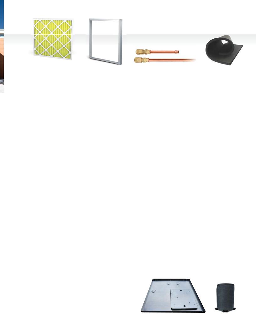
MERV-8 or MERV-13 |
2" 4-Sided Filter |
Schrader |
Closed Cell Foam |
Filter Option |
Rack Option |
Charging Valves |
Insulation (Optional) |
Quiet Operation
Noise reduction is a critical consideration of the unit design. All LV units have a distinct floating base pan; the compressor is mounted on a heavy steel plate which rests on a high density rubber pad on the base of the unit. In addition, compressors are mounted on rubber grommets. This double isolation, distinct to FHP equipment, is standard in all LV units preventing vibration and noise transmission from the compressor to the unit structure, resulting in exceptionally quiet operation.
The LV offers optional 1/2" thick, closed cell foam insulation to help aid indoor air quality (IAQ) and to further attenuate low frequency noise from the compressor compartment. The closed cell foam insulation option is available in all unit sizes. For additional sound attenuation, an optional compressor blanket is available on unit sizes 024 and above.
Serviceability
All units are designed to be serviced from the front of the unit. Schrader valves for high and low pressure gauges and the electrical box components are easily accessible for diagnosing and servicing the unit. Insulated bulkheads in all units, separate the compressor section from the blower section, allowing the unit to be serviced during operation.
Large removable panels aid in servicing the unit, when necessary. Separate electrical knockouts in the unit corner post allow for easy and safe routing of high and low voltage lines to the inside of the cabinet.
Unit Configurations
All units are available in horizontal, vertical and counterflow configurations. Additionally, several options of return air and supply air are offered as standard, providing configuration flexibility.
Filter Racks and Options
Units come standard with a 1" filter rack and construction filter. A 2" four-sided filter rack and pleated filter is optional and greatly improves air filtration. Filter doors allow for easy routine maintenance and changing of the air filter. A 1" return duct collar is integral to the filter rack eliminating the need for field mounted duct collars.
MERV-8 and MERV-13 Filters
The optional MERV-8 or -13 filter is most advantageous for premium air filtration on commercial HVAC projects. High efficiency filtration is a cost-effective way of upgrading air quality while maintaining low pressure drop and sustaining long service life. These filters effectively remove up to 98% of airborne matter, such as fine particulates, bacteria, smoke, gases and allergens including dust mites, pollen, mold spores, dust and smog. MERV-8 and MERV-13 rated filters are a minimum requirement for EQ credits 3.1 and 5 on LEED projects. With the standard ECM constant airflow motor the LV is prepared to handle higher external pressure drops when utilizing the higher efficiency MERV-13 filters.
Standard |
Optional |
Subject to change without prior notice.
5 | LV Model | Commercial Geothermal Heat Pumps
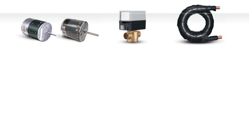
Constant Airflow |
Constant Torque |
2-Way Valve with |
Coax Coil |
ECM Option |
ECM Option |
Actuator |
|
Fan Motor
Permanent Split Capacitor Motors (PSC)
The standard motor for all LV model heat pumps is a PSC motor. For all models other than 575 V units, the supplied motor is a three speed motor. 575 V motors are single speed.
Hanging Brackets
All horizontal units come standard with hanging bracket kits for suspending the unit from field supplied hanger rods. These kits include heavy-duty steel brackets and rubber grommets for sound and vibration isolation from the building structure.
ECM Constant Torque Motor (Optional)
The LV’s constant torque blower motor option offers improved efficiency (up to 33%) over the standard PSC motor. This motor is similar in function to a PSC, but can handle up to 1 in.w.g. external static pressure making it a wise choice for high filtration applications. These motors are available in unit sizes 015 to 070. This ECM motor option is an excellent choice for retrofit. The constant-torque motors do not require a neutral wire for 460/3 power.
ECM Constant Airflow Motor
The LV’s new high efficiency ECM motor option, available in 1/3hp to 1hp, provides constant airflow in a wide static pressure range up to 1 in.w.g. Available in unit sizes 015 to 070, this motor is a great choice in high filtration applications, such as MERV-13. The motor has a soft start/stop feature, keeping noise to a minimum. LV units outfitted with any ECM motor can see an efficiency boost with up to 1.8 additional points of EER.
Passive dehumidification can be achieved with the constant airflow ECM by reducing nominal airflow by 15%. This control feature lowers air coil temperature and prevents over-cooling of the space when in dehumidification mode. IMPORTANT NOTE: The constant airflow ECM requires a neutral wire in a 460V application.
Water Connections
All water connections are heavy-duty bronze FPT fittings securely fastened to the unit corner post. This allows connecting to a flexible hose kit without the use of a backup wrench making for easier, faster installation.
Two-Position Water Valve
The two-position motorized water valve is optional on all unit sizes and is a great energy savings option. The valve opens to allow 100% fluid flow through the coaxial heat exchanger only when there is a call for cooling or heating. Closing off fluid flow to the unit when there is no call for cooling or heating reduces system operating costs, when using variable speed pumping, by reducing the speed of the primary loop pumps.
Refrigerant Circuit
LV units are designed using the optimum combination of compressor, water and air coils to provide peak performance. LV units are rated to withstand 600 PSIG working refrigerant pressure and 400 PSIG working water pressure.
Heavy-duty heat pump compressors are used in all units. Rotary, reciprocating and scroll compressors offer optimum performance for each unit size.
Subject to change without prior notice.

boschheatingandcooling.com | 6
Compressors |
Tin Plated with Coated Fin |
Blower Housing |
|
Evaporator Coil (Optional) |
(with Removable Inlet Ring) |
Refrigerant to water heat exchangers are coaxial tube-in- tube type providing a robust construction, ensuring years of trouble free operation. Coaxial coils are selected and designed for peak performance, offering the best combination of low water pressure drop and maximum heat transfer in both the cooling and heating modes. Standard coaxial coils have a copper interior water tube and a steel outer shell. Optional Cupro-Nickel coils are available for applications where the water is of lower quality.
In geothermal applications where fluid temperatures can drop below the dew point of the surrounding air, optional insulation is available to prevent water coils and refrigerant piping from sweating.
Air side refrigerant coils have copper tubes, aluminum fins and side plates to prevent corrosion.
Air coils are state of the art, employing lanced fin and rifled tubing for maximum heat transfer. Large face areas result in lower face velocity reducing sound while ensuring high latent heat removal for maximum dehumidification in the cooling mode.
A pilot operated four-way reversing valve in the refrigeration circuit allows the unit to operate in either the heating or cooling mode. All FHP units have the reversing valve energized in cooling mode. This will ensure you are not left without heat in the middle of winter, should the reversing valve coil fail.
Refrigerant flow to the air coil is metered by capillary tubes as standard in LV units. Thermal Expansion Valves come with the optional Extended Range LV and are designed to vary the flow of refrigerant depending on the load. TXV’s provide unit optimization and a more stable control over a wider range of operating conditions.
Evaporator Coil and DuoGuardTM (Option)
Air handling sections come standard with a copper tube aluminum fin evaporator coil. Available as an option is the DuoGuardTM evaporator coil protection system. DuoGuardTM Protection® - Tin Electro-Plated Copper Tubing with High-Tech Polymer Coated Aluminum Fins will aid in protecting the evaporator coil from most forms of corrosive elements in the airstream. The tin plating provides a best-in-class protection of the copper tubing from formicary corrosion while the fin coating provides protection against salt spray and other corrosive elements. DuoGuardTM protected coils are able to exceed 1000 hours salt spray per ASTM standard B-117.
Blower Housing
A removable inlet ring is a standard feature of the blower housing on all unit sizes. The removable inlet ring helps facilitate motor removal without having to remove the fan housing from the cabinet.
Unit Protection Module
Each LV Model is factory provided with a Unit Protection Module (UPM) that controls the unit operation and monitors the safety controls that protect the unit. The UPM interfaces with the thermostat or direct digital controller. The main purpose of the UPM is to protect the compressors by monitoring the different states of switches and sensors. This module provides time delays and protects the unit against freezing of the water to refrigerant and air to refrigerant heat exchangers as well as condensate overflow.
Subject to change without prior notice.

7 | LV Model | Commercial Geothermal Heat Pumps
TXV Valve (Optional) |
UPM Control Board |
Safety controls include the following as standard:
High pressure switch located in the refrigerant discharge line.
Low pressure switch located in the unit refrigerant suction line.
Standard low fluid temperature (freeze) protection sensor. The freeze protection sensor, located on the refrigerant liquid line entering the coaxial heat exchanger, is designed to disable compressor operation when the unit is in the heating mode, should the refrigerant temperature fall below either 26°F (-6.6°C) or 15°F (-9.4°C).
Condensate overflow protection sensor is standard and factory mounted in the drain pan of the unit.
Low air coil temperature (freeze) protection sensor disables the compressor when the refrigerant entering the air coil drops below 30°F (-1.1°C).
UPM Control Board Features
Condensate Overflow Protection — The UPM controller continuously monitors the drain pan for high condensate water level, and if this exceeds normal operating levels, the compressor operation is interrupted to protect against drain pan overflow.
Anti-Short Cycle Timer — 5 minute delay on break timer to prevent compressor short cycling.
Random Start — Each controller has a unique random start delay ranging from 270 to 300 seconds after power is applied to the board. This will prevent the simultaneous start of multiple units after a power outage.
Low Pressure Bypass Timer — The low pressure switch is bypassed for 120 seconds after a call for compressor operation to prevent nuisance low pressure lockouts during cold start-up in the heating mode.
Brownout/Surge/Power Interruption Protection
— Prevents compressor operation should the voltage drop below 10% of unit rated value. The unit will restart once the voltage is within tolerance and the random start has timed out.
Malfunction (Alarm) Output — The controller has a set of contacts for remote fault indication. This can be either a steady output or can be set to pulse with the fault code. Two connections are available - one to provide a 24 volt output, the other to provide a dry contact.
Test Service Mode — A dip switch setting is provided to reduce all time delay settings to 10 seconds maximum during troubleshooting for verification of unit operation.
LED Fault Indication — Two LED indicators are provided as follows:
Green: Power LED indicates 18 – 30 VAC present at the board.
Red: Fault indicator with blink codes identifying the particular fault. This information is available via the malfunction (alarm) output contacts.
1 Blink - High Pressure
2 Blinks - Low Pressure
3 Blinks - Low Fluid Temperature (Freeze Protection)
4 Blinks - Condensate Overflow
5 Blinks - Brownout condition
Subject to change without prior notice.

Intelligent Reset—If a fault condition is initiated, the 5 minute delay on break time period is initiated and the unit will restart after this delay expires. The UPM is configurable for either 2 or 4 fault occurrences before going into a hard lockout. The selection is made through a dip switch setting on the board. If the fault condition still exists or reoccurs twice or four times within one hour, the unit will go into a hard lockout and requires a manual lockout reset. A condensate overflow fault will, however, put the unit into a hard lockout immediately.
Lockout Reset—A hard lockout can be reset by turning the unit thermostat off and then back on or by shutting off unit power at the circuit breaker. The method of reset is selectable by the dip switch on the board.
Additional Options
Blower monitor relay
Compressor monitor relay
Phase monitor
Pump relay
Fire alarm relay
Fault LED light
50, 75 or 100 VA transformer option
40 Amp disconnect switch
Single and three phase
Hot Gas Reheat
Hot gas reheat (HGR) allows the user to not only control space temperature, but also humidity levels within the conditioned space. Excessive moisture in the space can promote mold growth leading to damage in the structure or interior surfaces, as well as reducing the air quality and creating an unhealthy environment.
Possible causes of excess humidity could be a byproduct of the unit having to operate under a widely varying load, an oversized short cycling unit, a high percentage of unconditioned outside air being introduced into the space, a high latent load in the space or any location where humidity infiltration is a problem.
boschheatingandcooling.com | 8
Typical unit control is by a wall mounted thermostat that senses temperature in the occupied space. By utilizing a humidistat in addition to the thermostat, LV units with Hot Gas Reheat are able to control the humidity levels in the space as well. The Hot Gas Reheat option allows cooling and dehumidification to satisfy both the thermostat and humidistat while preventing over-cooling of the space while in the dehumidification mode.
Once the thermostat reaches set point temperature, the humidity is above set point, the unit controller will energize the reheat valve operating the unit in hot gas reheat mode, first cooling and dehumidifying, then reheating the air (using hot refrigerant gas) before delivering it to the space, usually 2° to 5°F below room temperature. The unit operates like a dehumidifier by reheating the air along a constant sensible heat line, while the relative humidity of the leaving air is reduced.This option offers significant energy savings over reheating air with electric heating coils.
The moisture removal capacity of a specific heat pump is determined by the unit latent capacity rating. A heat pump’s latent capacity can be determined by reviewing the heat pump specification data sheets. Depending upon the entering water and air conditions, a total and sensible capacity can be interpolated from the data sheets. Subtracting sensible capacity from total capacity yields latent capacity. Dividing the latent capacity by 1069 converts the amount of moisture removal from BTU/Hr. to Pounds Per/Hr.
A hot gas reheat valve and a reheat coil are included in the refrigerant circuit. The refrigerant circuit in the cooling and heating mode is identical to a standard heat pump.
In the reheat mode, the compressor discharge gas is diverted through the reheat valve to the reheat coil which is located downstream of the cooling coil. The superheated refrigerant gas reheats the air leaving the cooling coil. The hot refrigerant gas then passes though the water to refrigerant coil where it is condensed to a liquid. From this point the rest of the cooling cycle is completed as in a regular heat pump. There are check valves to prevent refrigerant flow into the reheat coil during standard cooling/ heating cycles.
Subject to change without prior notice.

9 | LV Model | Commercial Geothermal Heat Pumps
Hot Gas Reheat Control Options
There are several ways to control heat pumps with hot gas reheat. You should choose the means that best suits your specific application. Please refer to the Hot Gas Reheat wiring diagrams for typical thermostat wiring. Most heat pump compatible thermostats in conjunction with a humidistat are acceptable for use, (Note: “O” output for reversing valve energized in cooling mode is required.) Combination thermostat/ humidistats are also available.
Special Considerations
Some applications require special attention to maximize the performance of the hot gas reheat function:
Low Temperature Well Water
Indoor Pool Dehumidifying During Winter Months (Re: Heating Mode)
Consult the factory for special application considerations.
Low Temperature Well Water
When low temperature well water is utilized as the water source (below 55°F), a means of establishing two flow rates, one for the cooling/reheat mode and one for heating mode is recommended. In the cooling mode at low entering water temperatures and standard flow rates, discharge pressures and corresponding discharge gas temperatures are relatively low. At these conditions, when the reheat mode is initiated, the low temperature discharge gas can reduce reheat capacity. A means to reduce the water flow rate and elevate the discharge pressure/temperature in cooling/reheat mode should be provided. Conversely, at low entering water temperatures in the heating mode, system suction pressure is reduced causing a loss in heating capacity. A means of providing higher flow in the heating mode should be supplied. The simplest way to accomplish the above is to install water regulating valves.
Indoor Pool Dehumidifying During Winter Months
It is important to remember that when in the reheat/ dehumidification mode the heat pump is cooling and reheating. A secondary means of heating the space during the dehumidification mode should be provided. For indoor pool environments, the indoor space temperature should be kept at least two (2) degrees F above
the pool water temperature. If this is not done the warm pool water attempts to heat the space and the humidity levels increase exponentially. The heat pump is normally sized to handle the design latent load moisture removal. A second heat pump or resistance heat should be provided to handle the structure’s shell loss load. DuoGuard™ evaporator coil option is required for this application.
Protective coatings are highly recommended for all pool applications, due to the highly corrosive chemical environment.
Sequence of Operation - Modulating Hot Gas Reheat (MHGRH)
Modulating Hot Gas Reheat differs from On/Off in that the reheat function is always active. The purpose of Modulating Hot Gas Reheat is to deliver supply air at or close to neutral conditions.
Air is cooled and dehumidified by the cooling coil to around 55°F DB/54°F WB. A sensor located in the supply air stream is set at the required leaving dry bulb temperature and will send a signal to the modulating hot gas reheat valve to direct the flow of hot gas to maintain that temperature. A typical application for this would be in treating 100% outside air. This air would be ducted directly into the space relieving the unit handling the zone of any outside air load. This can result in a smaller zone unit, less airflow and a savings in both initial and operating cost.
Control of the hot gas modulation is by the thermostat in the supply air duct or through a building management system. A separate controller is used to control the unit itself.
Hot Gas Bypass
The function of the hot gas bypass valve is to prevent icing of the air coil when the unit is operating at low cooling load conditions. This situation could arise if the space experiences widely different loads, for example a conference center or if a unit is sized for heating, it could be oversized for cooling. Without a hot gas bypass circuit the evaporating temperature could fall and ice could form on the coil restricting airflow and aggravating the situation. Eventually the heat pump could lock out on air coil freeze protection.
Subject to change without prior notice.
The hot gas bypass valve located in the compressor discharge line diverts hot gas to the inlet of the air coil. The valve is factory set to open when the evaporating pressure falls to 90 PSI and will modulate to prevent the pressure falling any lower. This setting is field adjustable and this set point may be adjusted as required.
Psychrometric Chart
|
|
|
|
|
|
|
|
85 |
|
|
|
|
|
85 |
|
|
|
|
|
|
|
|
|
|
|
|
|
|
|
|
|
85 W |
|
|
|
|
|
|
|
|
|
|
80 |
|
|
|
|
|
|
ET BU |
|
|
|
|
|
|
|
|
|
|
|
|
|
|
|
|
LB |
TE |
|||
|
|
|
|
|
|
|
|
|
|
|
|
|
|
80 |
|
||
|
|
|
|
|
|
|
|
|
|
|
|
|
|
|
|
|
MP |
|
|
|
|
|
|
|
|
|
|
|
|
|
|
|
|
|
ER |
|
|
|
|
|
|
|
|
|
|
|
|
|
|
|
|
|
ATUR |
|
|
|
|
|
|
|
|
|
|
|
|
|
|
|
|
|
E - |
|
|
|
|
|
|
|
|
|
|
|
|
|
|
|
|
|
°F |
|
|
|
|
|
|
75 |
|
|
|
|
80 |
|
|
75 |
|
|
|
|
|
|
|
|
|
|
|
|
|
|
|
|
|
|
|
||
|
|
|
|
|
|
|
|
|
|
|
|
|
Entering |
- °F |
|
||
|
|
|
|
|
|
|
|
|
|
|
|
|
TEMPERATURE |
|
|||
|
|
|
|
|
70 |
|
|
|
7 |
5 |
|
|
|
70 |
|
||
|
|
|
|
|
|
|
|
|
|
|
|
|
|||||
|
|
|
|
|
|
|
|
|
|
|
|
|
|
|
|
||
|
|
|
|
65 |
|
|
70 |
|
|
|
|
|
|
65POINT |
|
||
|
|
|
|
|
|
|
|
|
|
|
|
|
|
||||
|
|
|
|
|
|
|
|
|
|
|
|
|
|
|
DEW |
|
|
|
60 |
|
% |
|
|
65 |
|
|
|
|
|
|
|
60 |
|
|
|
|
|
0 |
|
|
|
|
|
|
|
|
|
|
|
|
|||
|
|
9 |
|
|
|
|
|
|
|
|
|
|
|
|
|
||
|
|
|
% |
|
|
|
|
|
|
|
|
|
|
|
|
|
|
|
Lvg. Coil |
0 |
|
|
Reheat |
|
|
|
|
|
|
|
|
|
|
|
|
55 |
8 |
|
|
|
|
|
|
|
|
|
|
55 |
|
|
|
||
|
|
|
60 |
|
|
|
|
|
|
|
|
|
|
||||
|
|
|
% |
|
|
|
|
|
|
|
|
|
|
|
|
||
|
|
0 |
|
|
|
|
|
|
|
|
|
|
|
|
|
|
|
|
|
7 |
|
|
|
|
|
|
|
|
|
|
|
|
|
|
|
|
|
|
% |
|
|
|
|
|
25% |
|
|
|
50 |
|
|
|
|
|
|
0 |
55 |
|
|
|
|
|
|
|
|
|
|
|
|
|
|
|
|
6 |
|
|
|
|
|
|
|
|
|
|
|
|
|
|
|
|
|
|
% |
|
|
|
|
|
|
|
|
|
45 |
|
|
|
|
|
50 |
50 |
|
|
|
|
|
|
|
|
|
|
|
|
|
|
|
|
|
40% |
|
|
|
|
|
|
|
|
|
40 |
|
|
|
||
|
|
|
|
|
|
|
15% |
|
|
|
|
|
|
|
|||
|
|
|
|
|
|
|
|
|
|
|
|
|
35 |
|
|
|
|
|
|
|
|
|
|
|
|
|
|
|
|
|
|
|
|
|
|
|
|
30% |
|
|
|
|
|
|
|
|
|
30 |
|
|
|
||
|
|
|
|
|
|
|
|
|
|
|
|
IDITY |
|
|
|
|
|
|
|
|
|
|
|
|
|
|
|
|
E HUM |
|
25 |
|
|
|
|
|
|
20% |
|
|
|
|
|
8% |
RELATIV |
|
|
|
|
|
|||
|
|
|
|
|
|
|
|
|
|
20 |
|
|
|
||||
|
|
|
|
|
DITY |
|
|
|
|
6% |
|
|
|
|
|
|
|
|
|
|
|
|
|
|
|
|
|
|
|
|
|
|
|
|
|
|
|
|
|
TIVE HUMI |
|
|
|
|
4% |
|
|
|
10 |
|
|
|
|
|
|
|
10% RELA |
|
|
|
|
|
|
|
|
|
|
|
|||
|
|
|
|
|
|
|
|
|
|
2% |
|
|
|
0 |
|
|
|
55 |
60 |
|
|
65 |
70 |
75 |
80 |
85 |
|
90 |
|
95 |
|
100 |
|
|
|
e.com |
DRY BULB TEMPERATURE - °F |
Figure 1
DDC Controls
The optional factory mounted DDC Controller is preprogrammed and installed on the unit with the Unit Protection Module (UPM) to be job site ready. The unit will operate in a 100% stand-alone control mode or connect to a Building Automation System (BAS) using open protocols BACnetTM, Modbus, N2 or LonWorks® (with an optional Lon card). Stand-alone DDC modules must use remote intelligent sensors and are to be programmed by the BACview® controller only.
Zone temperatures, leaving air temperatures and water temperatures can be monitored from the central control computer and unit fault indication displayed. Available inputs/outputs include:
Discharge air temperature
Leaving water temperature
Fan run time
Override time remaining
boschheatingandcooling.com | 10
Night setback status
Percent of units cooling
Percent of units heating
Cooling set point
Heating set point
Status of all the alarms
Space temperature
Occupied heating and cooling set points
Continuous or cycle fan during occupied mode
Command for occupied or unoccupied mode
Command for override of the unoccupied mode (unit resorts to occupied set points)
Set point adjustment
DDC Room Sensors
To complement the controller, Bosch offers a line of intelligent space sensors, which provide precision measurement and communication capabilities in an attractive low profile enclosure. A hidden communications jack provides access to the HVAC control system for commissioning and maintenance.
Models available include:
The RS Pro has a large LCD display and easy-to- use occupant controls for set point adjustment.
The RS Plus offers a local set point adjustment and override to an occupied mode and LED indication of current status.
The RS Standard which has no local temperature set point adjustment.
A BACview® hand held diagnostic tool is available to allow local access to display and modify user defined properties without any computer software. These space sensors will monitor, sense and provide local control for the room.
BACview® Hand Held
Diagnostic Tool
Subject to change without prior notice.
11 | LV Model | Commercial Geothermal Heat Pumps
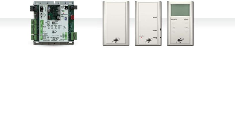
DDC Control Board |
RS Base |
RS Plus |
RS Pro |
|
DDC Sensor |
DDC Sensor |
DDC Sensor |
DDC Zone Sensors*
The Pro Zone Sensor (ZS) has an LCD screen that can display the current temperature and set temperature. It can also display relative humidity and CO2 settings as
well as their current readings. It comes with a button for additional information that can be displayed.
The Pro ZS can be ordered in any of the following combinations:
Temperature setting only
Temperature with relative humidity settings
Temperature, relative humidity, and CO2 settings
The Plus Zone Sensor (ZS) has a little different look to it. It has a occupied indicator that identifies the sensor to be operating in occupied conditions. It comes with a slide bar of for some manual temperature control in the occupied mode +/- setting can be adjusted
during commissioning.
The Plus ZS can be ordered in any of the following combinations:
Temperature setting only
The Base Zone Sensor (ZS) is limited to only sensing capabilities without local controllability. This zone sensor offers a basic look and blends into most decors.
The Base ZS can be ordered in any of the following combinations:
Temperature sensor
Temperature and relative humidity sensor
*DDC Zone Sensors available through Applications Special Handling Sheet. When the Zone Sensors (ZS) are available as a standard option they will replace the Room Sensors (RS).
Waterside Economizer
Common Waterside Economizer Applications
Commercial application where perimeter heating is taking place while core cooling is required. Perimeter heat pumps operating in the heating mode extract heat from the building loop, thus dropping the building loop fluid temperature. Internal core cooling requirements are usually high even in the winter months due to people, lighting, and equipment loads. The moderate temperature loop water circulated through a core heat pump’s waterside economizer coil can provide free-cooling without the use of mechanical cooling (Compressors). Also, in many areas code requires some type of economizer cycle. Waterside Economizers in lieu of air side economizers are an inexpensive way to satisfy code requirements in commercial applications.
Can also be sized up for preheating.
Tenant build out commercial applications where the central chilled water fluid loop serves as a individual zoned heat pump condenser water. In this application low temperature fluid is always available for free-cooling.
Fluid Flow
Fluid flow through heat pumps equipped with waterside economizer coils is directed by the use of a single three-way motorized ball valve. Flow is either through the waterside economizer coil and then through the condenser or through the condenser only. When applying these units to a variable speed pumping system, a separate field provided means of positive flow shut-off is required. (Re: A positive shut-off solenoid valve located down stream of the heat pump. See figure 2 on next page).
Subject to change without prior notice.

boschheatingandcooling.com | 12
Waterside |
Fluid Differential |
Economizer (Optional) |
Pressure Switch (Optional) |
Aquastat Fluid Differential Pressure Switch
The aquastat controller is mounted to the heat pump electrical control box. All electrical control wiring is factory installed. The controller is supplied with an external range adjustment and screwdriver slot. Actual range is -30° to 100°F and requires field setting. The remote bulb stored inside the heat pump for shipping requires field mounting.
Recommended settings: 45° F Cool, 90° F Heat
Air Side Pressure Drop
The air side pressure drop shown on the waterside economizer performance tables is considered as additional heat pump external static pressure. Refer to Bosch Select Tools selection software for blower performance and to determine if the unit requires an optional fan upgrade.*
*See fhp-mfg.com for BST Software.
The function of the differential pressure switch is to prevent or stop compressor operation should the water supply fail. This will prevent the unit from locking out on a safety requiring a manual reset to restart. This optional control is internally mounted and factory installed.
The switch is piped between the water entering and leaving connections. Should the pressure drop across the water to refrigerant heat exchanger and fall below set value, the switch will open de-energizing the compressor. The blower operation will not be affected by this option.
Energy Management Switch (EMS)
This switch allows you to connect to an energy management system that can turn the unit off and on.
3-Way motorized ball valve
|
|
|
Waterside |
|
N.O. |
|
N.C. |
economizer coil |
Fluid to refrigerant |
|
|
|
||
Aquastat |
|
|
|
heat exchanger |
MBV |
|
|
|
|
|
N.O. |
|
|
|
|
|
|
|
|
Fluid in |
|
|
|
|
|
“Bulb Strapped to Fluid” |
Positive shut-off solenoid |
||
|
in Line (field installed) |
|
valve for variable speed |
|
|
|
|
|
pumping system |
(field installed)
Figure 2
Subject to change without prior notice.

13 | LV Model | Commercial Geothermal Heat Pumps
Thermostats
Accessories
Thermostats
The unit control may be as simple as a single stage thermostat or the unit may have a DDC controller integrated into the building management system.
All external low voltage control wiring is made to the thermostat terminal located in the unit electrical box.
Thermostats may be manual change over, auto change over, programmable or non-programmable depending on the requirements of the project. A full line of thermostats are available as an accessory.
Hose Kits
Hose kits are recommended between the unit and system loop piping. This will help eliminate the transmission of vibration and noise from the unit to the space.
Hoses are fire rated fiber reinforced EPDM Stainless Steel braid hoses with swivel connections.
Maximum working pressure 400 PSI for sizes 1/2" – 1" diameter and 300 PSI for sizes 1 1/4" – 2".
A variety of hose kits are available depending on the job requirement.
Kit 1: Hoses only. 3/4" through 2" diameter hoses are available with 24" and 36" hose lengths. 1/2" diameter hose kits are available only with 12" long hoses.
Kit 2: Hose kit 1 with ball valves on the supply and return hoses. Valves have P/T (pressure/temperature) ports to facilitate pressure and temperature readings.
Kit 3: Hose kit 2 with an automatic flow control valve. The design flow rate is preset at the factory per the design conditions and will automatically limit the flow to this value. This will greatly facilitate balancing of the fluid loop and ensuring each unit gets the required flow.
Kit 4: Hose kit 3 with a Y-strainer and blow down valve on the supply side. The filter screen is 20 mesh, 304 stainless steel to help prevent dirt and debris from entering the water coil.
Kit 5: Hose kit 3 with a 24 v 2 position solenoid valve. This could be used to shut off flow to the unit when there is not a call for heating or cooling. A typical application would be with VFD pumping.
Kit 6: Hose kit 4 with a 24 v 2 position solenoid valve. Hose kit options are available in the accessories section of the BST selection software.
Subject to change without prior notice.

boschheatingandcooling.com | 14
Unit Configuration Diagrams
Counterflow
Compressor Access
Condenser
Water Out 
Condenser
Water In
Electrical
Knock-Outs
Blower Access |
Condensate |
|
Drain |
Figure 3
Left Hand Return Top Discharge FLT |
Right Hand Return Top Discharge FRT |
|
|
Access
Panels
Condenser
Water Out
Condenser
Water In
Condensate
 Electrical Drain
Connections
Figure 4
|
Typical Horizontal Unit Configurations |
|
|
Front |
Return Air Left |
Return Air Right |
Front |
|
|
||
|
Condensate |
|
|
|
Drain |
|
|
Straight Through FLS |
End Blow FLE |
End Blow FRE |
Straight Through FRS |
|
|||
Figure 5 |
|
|
|
Subject to change without prior notice.
15 | LV Model | Commercial Geothermal Heat Pumps
Systems
LV Models may be used in a variety of different applications depending on the system design. An overview of tower/boiler and geothermal systems is given below. There could be several variations and combinations of these systems.
Cooling Tower/Boiler Systems
will keep the fluid within certain temperature limits typically 70°F in winter and 85°F in summer by cycling either the cooling tower or boiler.
In today’s modern buildings the interior core usually has a net cooling requirement year round irrespective of the outside temperature. This is due to the internal heat gains from people, office equipment and lighting. The heat from heat pumps operating in cooling is rejected to the common water loop and is absorbed by heat pumps on the building’s perimeter that are in the heating mode. In effect the system is transferring energy around the building areas from where it is in excess to those areas where it is needed. In many instances we find a balanced system where the heat generated in the interior space is sufficient to heat the perimeter, resulting in neither the cooling tower nor boiler operating. This concept, unique to a water source system, provides the most energy efficient system on the market.
Water source heat pumps with cooling tower/boiler systems have been used for many years and are recognized as having a low installation cost and providing more energy efficient operation than most other systems on the market.
In a typical building, each office or space would receive its own heat pump. This ensures that the unit will independently satisfy the heating or cooling requirements for that space irrespective of the requirements of any other space. Unlike some other systems, this offers individual control and enhanced comfort in all areas.
All the units are connected to a common water loop containing, in addition to the heat pumps, a cooling tower, boiler, a primary and standby pump and a loop water temperature controller. In the summer cooling mode, the units are cooling and rejecting heat to the water loop. This heat is then rejected to the atmosphere through a cooling tower. In winter, heat is taken from the loop and, together with the compressor’s heat of compression, used to heat the space. The heat removed from the loop is then replenished by the boiler. The loop water temperature controller
Geothermal Systems
The earth has a tremendous capacity of storing thermal energy, which can be utilized to heat or cool a building.
A geothermal system offers all the benefits of a cooling tower and boiler system with the additional advantage of having overall greater energy efficiency. As the cost of energy increases, geothermal installations are becoming the system of choice by developers and design engineers.
There are several alternative methods of utilizing the energy contained in a geothermal system, giving the design engineer several options for selecting the one that is right for a particular application.
Earth Coupling Options
Ground Loop Systems (Closed Loop)
Lengths of high density polyethylene piping are buried in the earth either in vertical bore holes or horizontal trenches depending on the space available.
Subject to change without prior notice.
 Loading...