

Bosch B6512, B5512, B4512, B4512E, B3512E Installation Manual
...
Control Panels
B6512/B5512/B4512/B3512 (B5512E/B4512E/B3512E)
en
Installation Manual


Control Panels Table of contents | en 3
Bosch Security Systems, Inc. Installation Manual 2018.07 | 16 | F.01U.287.180
Table of contents
1
Certifications, approvals, listings, and safety 8
1.1 Listings and approvals 8
1.1.1 UL 8
1.1.2 ULC 8
1.1.3 Security Industry Association (SIA) 8
1.1.4 Department of Defense (DoD) 8
1.1.5 Department of Energy 8
1.1.6 California State Fire Marshal (CSFM) 8
1.1.7 National Institute of Standards and Technology (NIST) 8
1.1.8 Federal Communications Commission (FCC) Rules 9
1.1.9 Industry Canada (IC) 9
1.1.10 CE 9
1.2 Safety 10
1.2.1 Lightning 10
1.2.2 Power 10
2
Introduction 12
2.1 About documentation 12
2.1.1 Related documentation 12
2.2 Bosch Security Systems, Inc. product manufacturing dates 13
3
System overview 15
3.1 Parts list 15
3.2 Control panel capacities 15
4
Installation checklist 16
5
Control panel installation 17
5.1 Installing the enclosure and wiring label 17
5.2 Installing the control panel 17
5.2.1 Earth ground 19
5.2.2 OUTPUT A jumper 19
5.3 Control panel to module wiring overview 19
6
Power supply 21
6.1 Primary (AC) power 21
6.2 Secondary (DC) power 21
6.2.1 Install the battery 21
6.2.2 Battery maintenance 23
6.2.3 Battery supervision 23
6.2.4 Battery discharge and recharge schedule 23
6.3 B520 aux power supply 23
6.3.1 SDI2 address settings 24
6.3.2 Supervision 24
6.3.3 Auxiliary power supply trouble conditions 24
6.3.4 Installation and control panel wiring (B520) 24
6.3.5 Powered device and battery wiring 26
7
Telephone communications 28
7.1 B430 Plug-in Communicator, Telephone 28
7.1.1 Supervision 28
7.1.2 Installation and module wiring (B430) 28
7.1.3 Diagnostic LEDs 29
7.2 Phone jack location 29

4 en | Table of contents Control Panels
2018.07 | 16 | F.01U.287.180 Installation Manual Bosch Security Systems, Inc.
7.3 Telephone line monitor 30
7.4 Called party disconnect 30
7.5 Communication failure 31
8
IP communications 32
8.1 On-board Ethernet connection 32
8.1.1 Supervision 32
8.1.2 Local programming 32
8.1.3 On-board Ethernet diagnostic LEDs 33
8.2 Conettix Plug-in cellular modules 34
8.3 B426 Ethernet Communication Module 34
8.3.1 Address and emulation settings 34
8.3.2 Supervision 34
8.3.3 B426 module faults 34
8.3.4 Installation and control panel wiring (B426) 35
8.3.5 Diagnostic LEDs 36
8.3.6 Local programming 38
8.4 B450 Conettix plug-in communicator interface 38
8.4.1 SDI2 address settings 38
8.4.2 Supervision 38
8.4.3 Installation and control panel wiring (B450) 38
8.4.4 Diagnostic LEDs 39
8.5 Compatible receivers for IP communication 40
9
Keypads, keyswitches, keyfobs and transmitters 42
9.1 Keypads 42
9.1.1 Keypads overview 42
9.1.2 B921C Two-line Capacitive Keypad with Inputs 43
9.1.3 Shortcuts and custom functions 43
9.1.4 Address settings 44
9.1.5 Supervision 44
9.1.6 Installation and control panel wiring (keypads) 44
9.1.7 Sensor loops overview and wiring (B921C/B942/B942W only) 45
9.1.8 Output wiring (B942/B942W only) 46
9.1.9 Troubleshooting 46
9.2 Keyswitches 46
9.2.1 Operation 46
9.2.2 Installation and control panel wiring (keyswitches) 46
9.3 RADION keyfobs and Inovonics pendant transmitters 47
10
On-board outputs 49
10.1 Circuit protection 49
10.2 Total available power 49
10.3 Open collector outputs 50
11
Off-board outputs 51
11.1 B308 octo-output module 51
11.1.1 SDI2 address settings 51
11.1.2 Supervision 51
11.1.3 Installation and control panel wiring (B308) 52
12
On-board points 54
12.1 Point sensor loops 54
12.1.1 Single EOL (and no EOL) resistor circuit style 54

Control Panels Table of contents | en 5
Bosch Security Systems, Inc. Installation Manual 2018.07 | 16 | F.01U.287.180
12.1.2 Dual EOL resistor circuit style 55
12.2 Point response time 56
13
Off-board points 57
13.1 B208 octo-input module 57
13.1.1 SDI2 address settings 57
13.1.2 Supervision 57
13.1.3 Installation and control panel wiring (B208) 57
13.1.4 Sensor loops overview and wiring 59
13.2 Off-board points test 61
13.3 Extra Point events 61
13.4 Missing point conditions 61
14
Wireless modules 62
14.1 B810 receiver 62
14.1.1 SDI2 address settings 62
14.1.2 Supervision 62
14.1.3 Installation and control panel wiring (B810) 62
14.2 B820 SDI2 Inovonics Interface Module 63
14.2.1 SDI2 address settings 63
14.2.2 Supervision 63
14.2.3 Installation and control panel wiring (B820) 63
15
Access control 65
15.1 B901 door controller 65
15.1.1 Address settings 65
15.1.2 Supervision 65
15.1.3 Installation and control panel wiring (B901) 65
15.2 Card reader wiring 66
16
Program and test the control panel 67
16.1 Program the control panel 67
16.1.1 Program the control panel with RPS 67
16.1.2 Program the control panel with the Installer Services Portal programming tool 68
16.1.3 Program the control panel with a keypad 68
16.2 Walk tests 68
16.2.1 Fire walk test 68
16.2.2 Intrusion walk test 69
16.2.3 Service walk test 69
16.2.4 Invisible walk test 70
17
Control panel board overview 71
18
System wiring diagrams 73
18.1 System wiring overview 73
18.2 Battery lead supervision wiring 74
18.3 2-wire smoke wiring (B201) 75
18.4 2-wire smoke wiring (D125B) 76
18.5 Notification appliance circuit wiring 76
18.6 SDI2 devices general system wiring 78
18.6.1 SDI2 bus wiring recommendations 78
18.7 Wiring label 81
19
Approved applications 82
19.1 Optional compatible equipment 82
19.1.1 Burglar applications 82

6 en | Table of contents Control Panels
2018.07 | 16 | F.01U.287.180 Installation Manual Bosch Security Systems, Inc.
19.1.2 Bank safe and vault applications 82
19.1.3 Fire applications 85
19.1.4 Enclosures 86
19.2 Combination fire and intrusion alarm systems 87
19.3 Compatible UL listed components 87
19.4 Standby battery requirements and calculations 89
19.4.1 Household Fire Warning equipment 91
19.5 UL 365 - Police Station Connected Burglar Alarm Units and Systems 92
19.6 UL 636 - Holdup Alarm Units and System 92
19.7 Required values to achieve 180s (ULC)/200s (UL) supervision interval 92
19.8 ULC 93
20
Keypad Installer menu 94
20.1 [1] Program menu (Programming) 101
20.1.1 [1] Reporting > [1] Phone menu parameters 101
20.1.2 [1] Reporting > [2] Network menu parameters 102
20.1.3 [1] Reporting > [3] Routing menu parameters 103
20.1.4 [1] Reporting > [4] Personal Note menu parameters 104
20.1.5 [2] Network > [1] Ethernet > (choose the bus module or on-board) > [1] Module
Parameters menu
105
20.1.6 [2] Network > [1] Ethernet > (choose the bus module or on-board) > [2] Address
Parameters menu
106
20.1.7 [2] Network > [1] Ethernet > (choose the bus module or on-board) > [3] DNS
Parameters menu
107
20.1.8 [2] Network > [2] Cellular > (choose the SDI2 cellular module or plug-in module) 108
20.1.9 [3] RPS > [1] RPS Passcode menu parameters 109
20.1.10 [3] RPS > [2] RPS Phone Number menu parameters 109
20.1.11 [3] RPS > [3] RPS IP Address menu parameters 109
20.1.12 [3] RPS > [4] RPS Port Number menu parameters 110
20.1.13 [4] Area Options menu parameters 110
20.1.14 [5] Keypad menu parameters 111
20.1.15 [6] Users menu parameters 112
20.1.16 [7] Points menu parameters 113
20.1.17 [8] Disable Programming menu 120
20.2 [2] Wireless menu 120
20.2.1 [1] RF Point Menu> [1] Enroll Point RFID 120
20.2.2 [1] RF Point Menu> [2] Replace Point RFID 120
20.2.3 [1] RF Point Menu> [3] Remove Point RFID 121
20.2.4 [2] RF Repeater Menu > [1] Add Repeater 121
20.2.5 [2] RF Repeater Menu > [2] Replace Repeater 121
20.2.6 [2] RF Repeater Menu > [3] Remove Repeater 122
20.2.7 [3] RF Diagnostic Menu > [1] RF Points 122
20.2.8 [3] RF Diagnostic Menu > [2] RF Repeater Menu 122
20.3 [3] Diags menu 123
20.3.1 [1] Wireless 123
20.3.2 [2] Network menu 123
20.3.3 [3] Cellular menu 123
20.3.4 [4] IP Camera 124
20.3.5 [5] Cloud 124
20.4 [4] Service Bypass (Serv Byp) menu 124

Control Panels Table of contents | en 7
Bosch Security Systems, Inc. Installation Manual 2018.07 | 16 | F.01U.287.180
20.5 [5] Versions menu 125
20.6 [6] Cloud menu 126
21
Specifications 127
21.1 Wire requirements 129
22
Appendix 130
22.1 Address settings 130
22.1.1 B208 address settings 130
22.1.2 B308 address settings 130
22.1.3 B901 address settings 131
22.1.4 B91x address settings 131
22.2 Reporting and device number information 132
22.2.1 Report format definitions 132
22.2.2 SDI2 address information 141
22.2.3 Device numbers (zzz, dddd) 142
22.2.4 Communication Trouble device numbers (zzzz) 142
22.2.5 Special User IDs (uuuu, iiii) 143
22.2.6 Keypad alarm virtual point numbers (ppp, pppp) 143
22.3 AutoIP 144

8 en | Certifications, approvals, listings, and safety Control Panels
2018.07 | 16 | F.01U.287.180 Installation Manual Bosch Security Systems, Inc.
1 Certifications, approvals, listings, and safety
This section provides certification and approval listings and safety information.
1.1 Listings and approvals
This document includes the section Approved applications, page 82. Refer to this section for
guidelines on installing the control panels in Underwriters Laboratories Inc. (UL) and firespecific applications.
1.1.1 UL
Listed for:
– UL 365 - Police Station Connected Burglar Alarm Units and Systems
– UL 609 - Local Burglar Alarm Units and Systems
– UL 636 - Holdup Alarm Units and Systems
– UL 985 - Household Fire Warning System Units
– UL 1023 - Household Burglar Alarm System Units
– UL 1076 - Proprietary Burglar Alarm Units and Systems
– UL 1610 - Central Station Burglar Alarm Units
– UL 1635 - Digital Alarm Communicator System Units
1.1.2 ULC
Listed for:
– ULC C1023 - Household Burglar Alarm System Units
– ULC C1076 - Proprietary Burglar Alarm Units and System
– ULC S303 - Local Burglar Alarm Units and System
– ULC S304 - Central and Monitoring Station Burglar Alarm Units
– ULC S545 - Residential Fire Warning System Control Units
– ULC S559 – Fire Signal Receiving Centres and Systems
1.1.3 Security Industry Association (SIA)
Listed for Control Panel Standard - Features for False Alarm Reduction ANSI/SIA CP-01-2010.
1.1.4 Department of Defense (DoD)
The B6512/B5512/B4512/B3512 control panels were granted approval for Department of
Defense (DoD) installations in Sensitive Compartmented Information Facilities (SCIF).
1.1.5 Department of Energy
This control panel operates on a transformer that has been reviewed by a third party and
deemed to be compliant to the Department of Energy, U.S. Energy Conservation Standard for
External Power Supplies (found in section 10 CFR 430.32(w)(1)(i) of the Federal Code) as an
indirect device.
1.1.6 California State Fire Marshal (CSFM)
Listed for Household Fire Alarm.
1.1.7 National Institute of Standards and Technology (NIST)
When communicating via a network, listed for Advanced Encryption Standard (AES), Federal
Information Processing Standards Publication 197 (FIPS 197).

Control Panels Certifications, approvals, listings, and safety | en 9
Bosch Security Systems, Inc. Installation Manual 2018.07 | 16 | F.01U.287.180
1.1.8 Federal Communications Commission (FCC) Rules
Part 15
This equipment was tested and found to comply with the limits for a Class B digital device,
pursuant to Part 15 of the FCC rules. These limits are designed to provide reasonable
protection against harmful interference when the equipment is operated in a commercial
environment.
This equipment generates, uses, and can radiate radio frequency energy; and if not installed
and used according to the instructions, can cause harmful interference to radio
communications.
Operation of this equipment in a residential area is likely to cause harmful interference, in
which case the user is required to correct the interference at his or her own expense.
Part 68
The B430 module by Bosch Security Systems, Inc. is registered with the Federal
Communication Commission (FCC) under Part 68, for connection to the public telephone
system using an RJ31X or RJ38X phone line connection jack installed by the local telephone
company.
Do not connect registered equipment to party lines or coin-operated telephones. Notify the
local telephone company and provide the following information before connecting the control
panel to the telephone network:
– The particular line to which you connect the module
– Make (Bosch Security Systems, Inc.), model (B6512/B5512/B4512/B3512), and serial
number of the control panel
– FCC registration number: ESVAL00BB430
– Ringer eq: 0.0B
1.1.9 Industry Canada (IC)
ICES-003 - Information Technology Equipment
This Class B digital equipment meets all requirements of the Canadian interference-causing
equipment regulations.
Cet appareil numérique de la Class A respecte toutes les exifences de règlement sue le
matériel brouilleur du Canada.
CS-03 - Compliance Specification for Terminal Equipment
The B430 module by Bosch Security Systems, Inc. meets the applicable Industry Canada
technical specifications. The Ringer Equivalence Number (REN) is an indication of the
maximum number of devices allowed to be connected to a telephone interface. The
termination of an interface may consist of any combination of devices subject only to the
requirement that the sum of the RENs of all the devices not exceed five.
Le présent matériel est conforme aux spécifications techniques applicables d'Industrie
Canada.
L'indice d'équivalence de la sonnerie (IES) sert à indiquer le nombre maximal de terminaux qui
peuvent être raccordés à une interface téléphonique. La terminaison d'une interface peut
consister en une combinaison quelconque de dispositifs, à la seule condition que la somme
d'indices d'équivalence de la sonnerie de tous les dispositifs n'excède pas cinq.
1.1.10 CE
Listed for:
– EMC
– LVD
– RoHS
10 en | Certifications, approvals, listings, and safety Control Panels
2018.07 | 16 | F.01U.287.180 Installation Manual Bosch Security Systems, Inc.
1.2 Safety
Notice!
After system installation and any control panel programming, perform a complete system test.
A complete system test includes testing the control panel, all devices, and communication
destinations for proper operation.
1.2.1 Lightning
The control panel design significantly reduces the adverse effects of lightning. Take
installation precautions to further reduce these adverse effects.
Effects of lightning
Electronics involved in a direct lightning strike or near a lightning strike can show adverse
effects. When lightning strikes, several things happen:
– An electromagnetic wave spreads from the center point of the strike inducing high
voltages onto nearby conductors.
– The voltage changes substantially on electrical grounds near the lightning strike.
– High voltages are induced onto anything directly struck by lightning.
The effects of lightning can include trouble events, alarm events, and physical damage.
Installation precautions
To minimize the undesirable effects from lightning:
– Do not run wiring outside the building.
– If you install the unit in a metal building, keep the wiring at least 2 ft (0.61 m) away from
external metal surfaces. Make a proper earth ground connection.
– Earth ground the unit correctly. Do not use an electrical ground or telephone ground.
– Avoid running wires near telephone, data, or power lines. Locating control panel wiring at
least 2 ft (0.61 m) away helps reduce the effects of lightning.
– When your data lines must cross the path of AC or other wiring, cross perpendicular to
the lines.
Warranty regarding lightning
The warranty does not cover physical damage due to lightning.
1.2.2 Power
!
Caution!
Remove all power (AC and battery) before making any connections. Failure to do so might
result in personal injury and/or equipment damage.
!
Caution!
Do not short-circuit the terminals of the transformer
If you short the terminals, the internal fuse opens. This causes permanent failure. Connect the
transformer to the control panel AC power terminals before you plug it into the power source.
Notice!
Plan ahead
Route telephone, SDI2 bus wiring, and sensor loop wiring away from any AC conductors,
including the transformer wire. AC wiring can induce noise and low level voltage into adjacent
wiring.
Control Panels Certifications, approvals, listings, and safety | en 11
Bosch Security Systems, Inc. Installation Manual 2018.07 | 16 | F.01U.287.180
!
Warning!
High current arcs are possible
The positive (red) battery lead and the terminal labeled BAT+ can create high current arcs if
shorted to other terminals or the enclosure. Use caution when you touch the positive lead
and the terminal labeled BAT+. Always disconnect the positive (red) lead from the battery
before you remove it from the terminal labeled BAT+.
!
Caution!
Battery terminals and wire are not power limited
Maintain a 0.250 in (6.4 mm) space between the battery terminals, battery wiring, and all
other wiring. Battery wiring cannot share the same conduit, conduit fittings, or conduit
knockouts with other wiring.
!
Caution!
Heavy discharges possible
The system can have heavy discharges if you exceed the maximum output ratings or install
the transformer in an outlet that is routinely switched off. Routine heavy discharges can lead
to premature battery failure.
Notice!
Use sealed lead acid batteries only
The charging circuit is calibrated for lead-acid batteries. Do not use gel-cell or NiCad
batteries.
12 en | Introduction Control Panels
2018.07 | 16 | F.01U.287.180 Installation Manual Bosch Security Systems, Inc.
2 Introduction
This section includes an introduction to documents for this product and other documentrelated instructions.
2.1 About documentation
This document has instructions for a trained installer to install, configure, and operate this
control panel, and optional peripheral devices.
(Bosch Security Systems, Inc. recommends that installers follow good wiring practices such as
those described in NFPA 731, Standard for the Installation of Electronics Premises Security
Systems.)
Throughout this document, the words “control panel” refer to all control panels covered by
this document (B6512/B5512/B5512E/B4512/B4512E/B3512/B3512E).
Notifications
This document uses Notices, Cautions, and Warnings to draw your attention to important
information.
Notice!
These include important notes for successful operation and programming of equipment, or
indicate a risk of damage to the equipment or environment.
!
Caution!
These indicate a hazardous situation which, if not avoided, could result in minor or moderate
injury.
!
Warning!
These indicate a hazardous situation which, if not avoided, could result in death or serious
injury.
Copyright
This document is the intellectual property of Bosch Security Systems, Inc. and is protected by
copyright. All rights reserved.
Trademarks
All hardware and software product names used in this document are likely to be registered
trademarks and must be treated accordingly.
2.1.1 Related documentation
Control panel documents
Control Panels (B6512/B5512/B4512/B3512) Release Notes*
Control Panels (B6512/B5512/B4512/B3512) Installation Manual
+
Control Panels (B9512G/B8512G/B6512/B5512/B4512/B3512) Operation Manual*
+
Control Panels (B5512/B4512/B3512) Program Entry Guide
+
Control Panel (B6512) Program Entry Guide
Control Panels (B6512/B5512/B4512/B3512) UL Installation Manual*
+

Control Panels Introduction | en 13
Bosch Security Systems, Inc. Installation Manual 2018.07 | 16 | F.01U.287.180
Control Panels (B6512/B5512/B4512/B3512) SIA Quick Reference Guide*
+
Control Panels (B9512G/B8512G/B6512/B5512/B4512/B3512) ULC Installation Manual*
*Shipped with the control panel.
+
Located on the documentation CD shipped with the control panel.
Keypad documents
Basic Keypad (B915) Installation Guide*
Two-line Alphanumeric Keypad (B920) Installation Guide*
Two-line Capacitive Keypad with Inputs (B921C) Installation Guide*
ATM Style Alphanumeric Keypad (B930) Installation Guide*
Touch Screen Keypad (B942/B942W) Installation Guide*
*Shipped with the keypad.
Optional module documents
2-wire Powered Loop Module (B201) Installation and Operation Guide*
Octo-input Module (B208) Installation and Operation Guide*
Octo-output Module (B308) Installation and Operation Guide*
Conettix Ethernet Communication Module (B426) Installation and Operation Guide*
+
Plug-in Telephone Communicator (B430) Installation Guide Installation Guide*
Conettix Plug-in GPRS Cellular Communicator (B442) Installation and Operation Guide*
Conettix Plug-in HSPA+ Cellular Communicator (B443) Installation and Operation Guide*
Conettix Plug-in Cellular Communicator (B444) Installation and Operation Guide*
Conettix Plug-in Communicator Interface (B450) Installation and Operation Guide*
+
Auxiliary Power Supply (B520) Installation and Operation Guide*
RADION receiver SD (B810) Installation Guide*
SDI2 Inovonics Interface Module (B820) Installation Guide*
*Shipped with the module.
+
Located on the documentation CD shipped with the module.
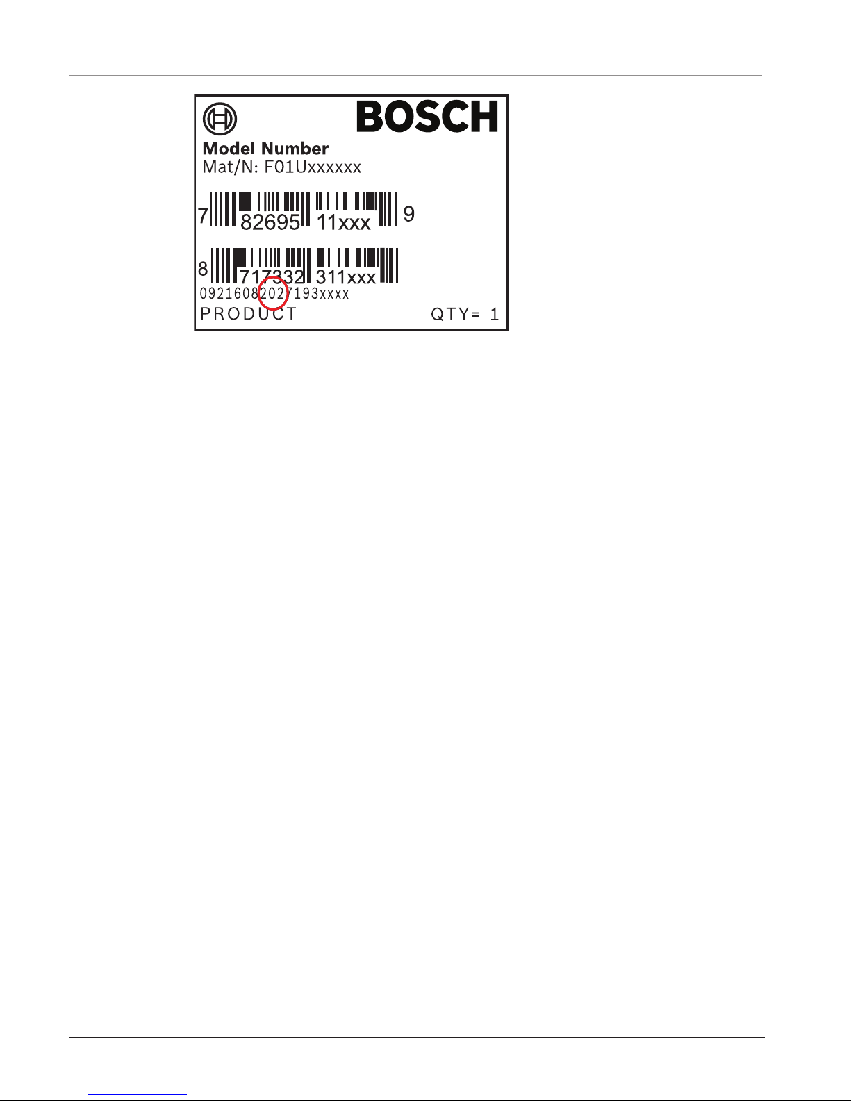
2.2 Bosch Security Systems, Inc. product manufacturing dates
Use the serial number located on the product label and refer to the Bosch Security Systems,
Inc. website at http://www.boschsecurity.com/datecodes/.
The following image shows an example of a product label and highlights where to find the
manufacturing date within the serial number.
14 en | Introduction Control Panels
2018.07 | 16 | F.01U.287.180 Installation Manual Bosch Security Systems, Inc.

Control Panels System overview | en 15
Bosch Security Systems, Inc. Installation Manual 2018.07 | 16 | F.01U.287.180
3 System overview
This section has the following information:
– Parts list, page 15
– Control panel capacities, page 15
– Accessories
– Features
3.1 Parts list
Control panels ship assembled from the factory with the following parts:
Literature
– Control Panels (B6512/B5512/B4512/B3512) UL Installation Manual
– Control Panels (B6512/B5512/B4512/B3512) Operation Manual
– Control Panels (B6512/B5512/B4512/B3512) SIA Quick Reference Guide
– Control Panels (B6512/B5512/B4512/B3512) Documentation CD
– Enclosure Wiring Label (B6512/B5512/B4512/B3512)
HW pack
– Mounting clips
– 1 kΩ EOL resistors
– Battery wires
– Four #6 x 3/4 in self threading screws
Assembly
– PC board
3.2 Control panel capacities
Features B6512 B5512/
B5512E
B4512/
B4512E
B3512/
B3512E
Number of users 100 50 32 10
Number of custom functions 6 4 2 1
Number of areas 6 4 2 1
Number of points 96 48 28 16
Number of outputs 91 43 27 3
Number of keypads 12 8 8 4
Number of doors 4 0 0 0
Number of octo-intput modules (B208) 9 4 2 0
Number of octo-output modules (B308) 9 5 3 0
Number of on-board Ethernet ports (“E” control panel variants
do not include an Ethernet port)
1 1 1 1
Number of B426 or B450 modules 1 1 1 1
Number of plug-in modules (B430, B440/B441/B442/B443/
B444)
1 1 1 1
Number of auxiliary power supply modules (B520) 4 4 2 2
Number of wireless receivers (B810/B820) 1 1 1 1

16 en | Installation checklist Control Panels
2018.07 | 16 | F.01U.287.180 Installation Manual Bosch Security Systems, Inc.
4 Installation checklist
Before you install and operating the control panel, read these instructions. If you do not read
and understand these instructions, you cannot properly install and operate the control panel.
The instructions do not remove the need for training by authorized personnel.
Install, operate, test, and maintain this device according to the control panel Installation and
System Reference Guide. Failure to follow these procedures may cause the device not to
function properly. Bosch Security Systems Inc. is not responsible for any devices that are
improperly installed, tested, or maintained.
The control panel Installation and System Reference Guide does not have special information
about local requirements and safety issues. Information on such issues is provided only to the
extent that it is needed for operation of the device. Make sure that you are familiar with all
safety-related processes and regulations in your area. This also includes how to act in the
event of an alarm and the initial steps to take if a fire breaks out. The operating instructions
should always be available on site. It is a required part of the system and must be given to the
new owner if the system is ever sold.
Install the enclosure and wiring label
– Installing the enclosure and wiring label, page 17
Install the control panel
– Mount the control panel
– Earth ground, page 19
– OUTPUT A jumper, page 19
Install and wire for telephone communication
– Telephone communications, page 28
Install and wire for IP communications
– IP communications, page 32
Install and wire the battery and the transformer
– Power supply, page 21
Begin to charge the battery while you install other devices
– Charge the battery
Install and wire arming devices
– Keypads, keyswitches, keyfobs and transmitters, page 42
Install and wire outputs
– On-board outputs, page 49
– Off-board outputs, page 51
Install and wire inputs
– On-board points, page 54
– Off-board points, page 57
– Wireless modules, page 62
Complete the installation
– Program and test the control panel, page 67
Control Panels Control panel installation | en 17
Bosch Security Systems, Inc. Installation Manual 2018.07 | 16 | F.01U.287.180
5 Control panel installation
Refer to Enclosures, page 86 to determine if the application requires a specific enclosure.
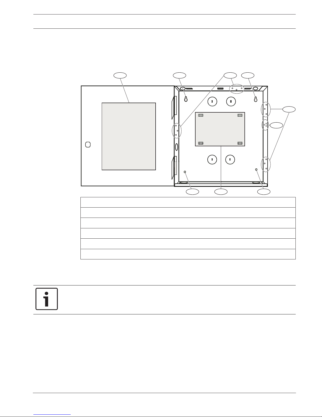
Enclosure overview
1 2 3
4
22 5
2
3
Callout ᅳ Description
1 ᅳ Control panel wiring label
2 ᅳ Enclosure mounting holes (4)
3 ᅳ Three-hole pattern for mounting modules (4)
4 ᅳ Mounting location for the tamper switch
5 ᅳ Mounting location for the control panel
5.1 Installing the enclosure and wiring label
Notice!
Electromagnetic interference (EMI)
EMI can cause problems on long wire runs.
1. Remove the knockouts.
2. Mount the enclosure. Use all enclosure mounting holes. Refer to the mounting
instructions supplied with the selected enclosure.
3. Pull the wires into the enclosure through the knockouts.
4. Position the supplied enclosure wiring label on the inside of the enclosure door.
5.2 Installing the control panel
1. Identify the control panel mounting location in the enclosure.
18 en | Control panel installation Control Panels
2018.07 | 16 | F.01U.287.180 Installation Manual Bosch Security Systems, Inc.
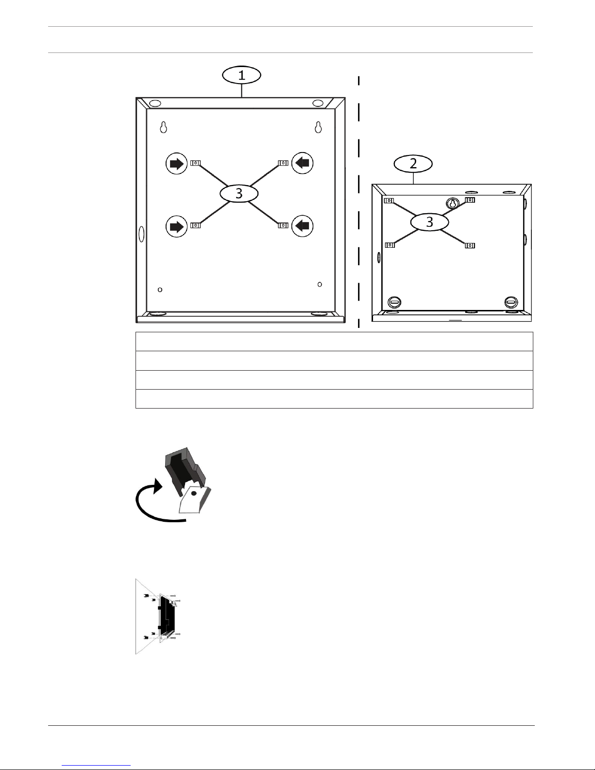
Callout ᅳ Description
1 ᅳ B10 Medium Control Panel Enclosure
2 ᅳ B11 Small Control Panel Enclosure
3 ᅳ Mounting clip locations for the control panel
2. Snap the four plastic standoffs onto the four enclosure support posts. If you install a B12,
attach the standoffs to the plate support posts. Do not attach the standoff screws.
3. Position the control panel on top of the standoffs.
4. Align the holes in the corners of the control panel with the openings at the top of each
standoff.
5. Attach and tighten the control panel to the standoffs with the supplied screws.
6. If you install a B12, rest the hook tabs on the mounting plate hooks within the enclosure.
Secure the lock-down tab to the plate mounting hole with the screw provided.
Control Panels Control panel installation | en 19
Bosch Security Systems, Inc. Installation Manual 2018.07 | 16 | F.01U.287.180
5.2.1 Earth ground
To help prevent damage from electrostatic discharges or other transient electrical surges,
connect the system to earth ground before making other connections. The earth ground icon
identifies the earth ground terminal. Recommended earth ground references are a grounding
rod or a cold water pipe. Make the connection using 14 AWG (1.8 mm) to 16 AWG (1.5 mm)
wire.
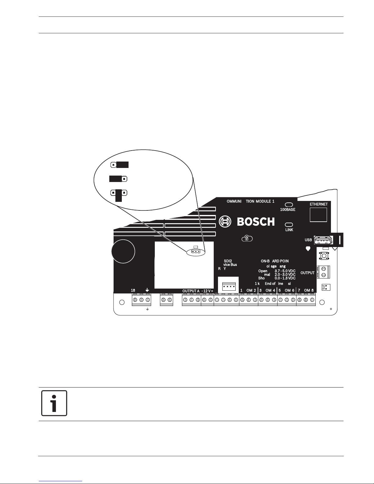
5.2.2 OUTPUT A jumper
OUTPUT A is a form C relay. Choose one of the following uses before you install and configure
OUTPUT A:
– +12 VDC (AUX power)
– COM terminal (parallel to all COM terminals)
– Dry contact (no voltage, not common)
P1
P1
P1
OUTPUT A (C terminal) = AUX PWR
COM AUX
OUTPUT A (C terminal) = COM
OUTPUT A (C terminal) = DRY
COM AUX
COM AUX
COM AUX
P1
TMPR
1 COM 2 7 COM 83 COM 4 5 COM 6
RESET
ETHERNET
COM AUX R Y G B
PWR A B COM
+ BAT -18VAC
B C
OUTPUT
NO C NC
OUTPUT A
7 COM 8
C
OUTPUT
B
USB
ETHERNET
100BASE-T
LINK
COMMUNICATION MODULE 1
1 k End of Line Resistors
Voltage Ranges
ON-BOARD POINTS
3.7 - 5.0 VDC
2.0 - 3.0 VDC
0.0 - 1.3 VDC
Open
Normal
Short
3 COM 4 5 COM 61 COM 2
R Y G B
SDI2
Device Bus
18 VAC
OUTPUT A
AUX
- 12 V +
The control panel ships with the jumper in the default position, AUX power. (OUTPUT A, ‘C’
terminal providing AUX PWR). To reconfigure the ‘C’ terminal as a COM terminal (parallel to all
COM terminals), remove the door covering the jumper pins, and move the jumper to the left
two pins. The OUTPUT A LED lights when OUTPUT A is active.
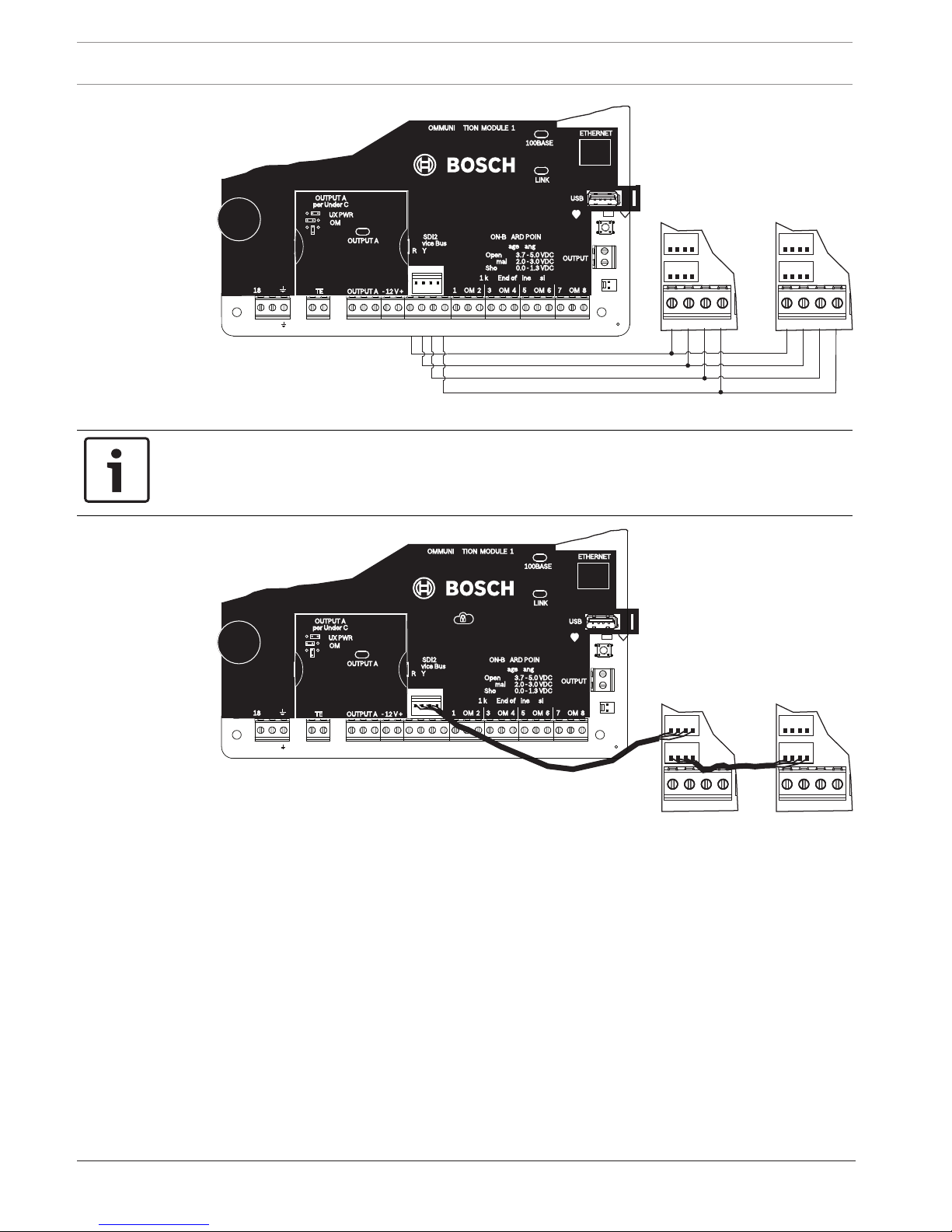
5.3 Control panel to module wiring overview
You can use interconnect or terminal wiring to connect devices to the control panel.
Using terminal wiring in parallel
Notice!
Wire size
For terminal wiring, use 18 AWG to 22 AWG (1.0 mm to 0.6 mm) wire.
20 en | Control panel installation Control Panels
2018.07 | 16 | F.01U.287.180 Installation Manual Bosch Security Systems, Inc.
PWR A B COM PWR A B COM
TMPR
1 COM 2 7 COM 83 COM 4 5 COM 6
RESET
ETHERNET
COM AUX R Y G B
PWR A B COM
+ BAT -18VAC
B C
OUTPUT
NO C NC
OUTPUT A
7 COM 8
C
OUTPUT
B
USB
ETHERNET
100BASE-T
LINK
COMMUNICATION MODULE 1
1 k End of Line Resistors
Voltage Ranges
ON-BOARD POINTS
3.7 - 5.0 VDC
2.0 - 3.0 VDC
0.0 - 1.3 VDC
Open
Normal
Short
3 COM 4 5 COM 61 COM 2
R Y G B
SDI2
Device Bus
18 VAC
BATTERY OUTPUT A
AUX
- 12 V +
OUTPUT A
OUTPUT A
Jumper Under Cover
AUX PWR
COM
DRY
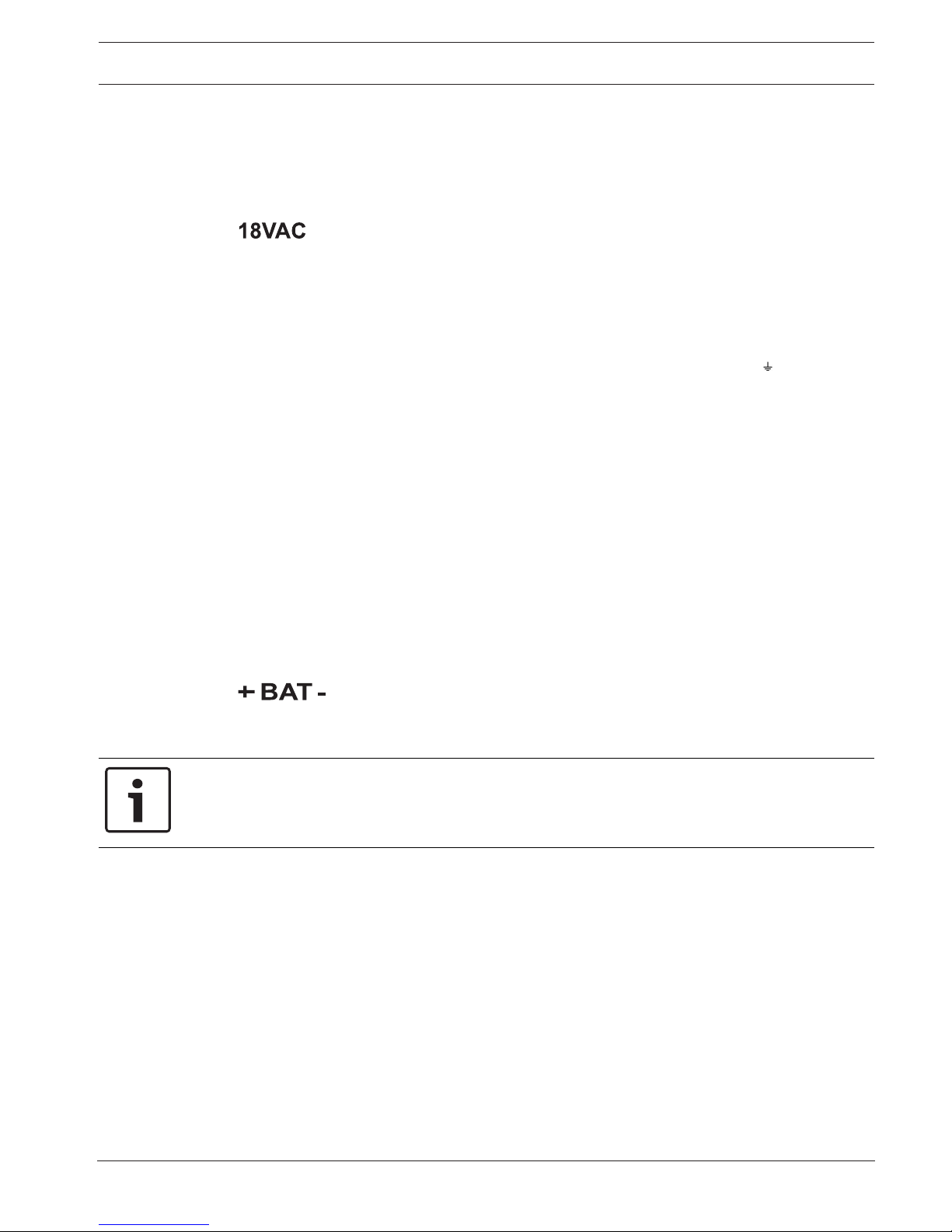
Using interconnect wiring
Notice!
More information
For more information on interconnect wiring, refer to SDI2 interconnect wiring.
PWR A B COM PWR A B COM
TMPR
1 COM 2 7 COM 83 COM 4 5 COM 6
RESET
ETHERNET
COM AUX R Y G B
PWR A B COM
+ BAT -18VAC
B C
OUTPUT
NO C NC
OUTPUT A
7 COM 8
C
OUTPUT
B
USB
ETHERNET
100BASE-T
LINK
COMMUNICATION MODULE 1
1 k End of Line Resistors
Voltage Ranges
ON-BOARD POINTS
3.7 - 5.0 VDC
2.0 - 3.0 VDC
0.0 - 1.3 VDC
Open
Normal
Short
3 COM 4 5 COM 61 COM 2
R Y G B
SDI2
Device Bus
18 VAC
BATTERY OUTPUT A
AUX
- 12 V +
OUTPUT A
OUTPUT A
Jumper Under Cover
AUX PWR
COM
DRY
Control Panels Power supply | en 21
Bosch Security Systems, Inc. Installation Manual 2018.07 | 16 | F.01U.287.180
6 Power supply
This section provides information on installing and maintaining primary power, batteries, and
auxiliary power.
6.1 Primary (AC) power
The control panel uses an 18 VAC, 22 VA internally fused transformer for its primary power
source. The control panel draws 125 mA when idle and 155 mA when in the alarm state. The
auxiliary power available for powered devices is 800 mA.
Surge protection
Transient suppressors and spark gaps protect the circuit from power surges. This protection
relies on the ground connection at the earth ground terminal marked with the icon. Ensure
that you connect the terminal to a proper ground.
Refer to Earth ground, page 19.
AC power fail
The system indicates an AC power failure when the following terminals do not have sufficient
voltage: VAC: The AC Fail Time parameter sets the amount of time without AC power before
the control panel reports the failure. It also sets the amount of time after the power returns
before the control panel reports restored power.
Self diagnostics at power up and reset
The system performs a series of self-diagnostic tests of hardware, software, and programming
at power up and at reset. The self-diagnostics tests complete in approximately 10 to 30
seconds.
If the control panel fails any test, a System Trouble message appears on the keypads.
6.2 Secondary (DC) power
A 12 V sealed lead-acid rechargeable battery (such as the D126/D1218) supplies secondary
power to maintain system operation during interruptions of primary (AC) power.
Notice!
Use sealed lead acid batteries only
The charging circuit is calibrated for lead-acid batteries. Do not use gel-cell or NiCad
batteries.
Extra batteries
To increase battery back-up time, connect a second 12 V battery in parallel to the first battery.
Use a D122/D122L Dual Battery Harness to ensure proper and safe connection.
D1218 Battery
The D1218 is a 12 V, 18 Ah battery for use in applications requiring extended battery standby
time. The control panel does not support more than 18 Ah.
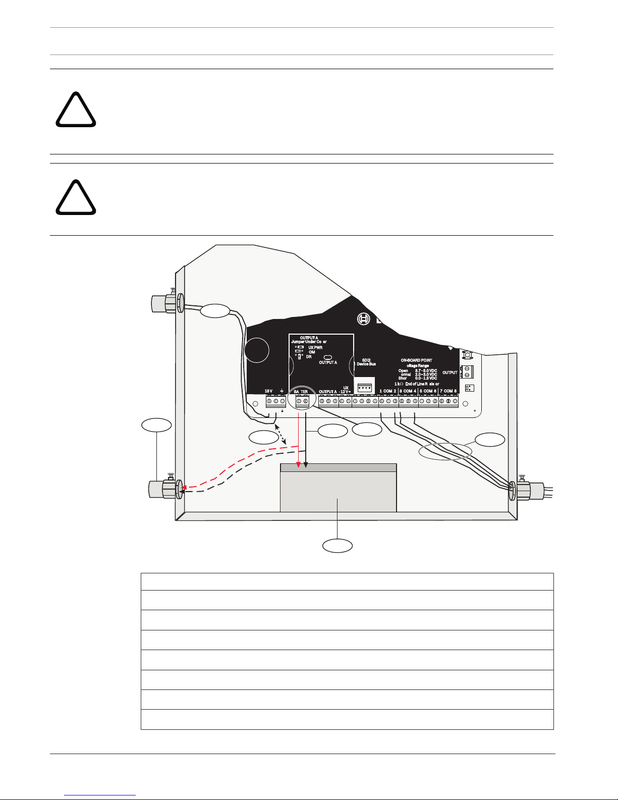
6.2.1 Install the battery
1. Put the battery upright in the base of the enclosure.
2. Locate the red and black leads supplied in the hardware pack.
3. Connect the black battery lead to BAT- .
4. Connect the other end to the negative (-) side of the battery.
5. Connect the red battery lead to BAT+.
6. Connect the other end to the positive (+) side of the battery.
22 en | Power supply Control Panels
2018.07 | 16 | F.01U.287.180 Installation Manual Bosch Security Systems, Inc.
!
Warning!
High current arcs are possible
The positive (red) battery lead and the terminal labeled BAT+ can create high current arcs if
shorted to other terminals or the enclosure. Use caution when you touch the positive lead
and the terminal labeled BAT+. Always disconnect the positive (red) lead from the battery
before you remove it from the terminal labeled BAT+.
!
Caution!
Battery terminals and wire are not power limited
Maintain a 0.250 in (6.4 mm) space between the battery terminals, battery wiring, and all
other wiring. Battery wiring cannot share the same conduit, conduit fittings, or conduit
knockouts with other wiring.
1
2
3
4
5
6
7
TMPR
1 COM 2 7 COM 83 COM 4 5 COM 6
RESET
ETHERNET
COM AUX
R Y G B
PWR A B COM
+ BAT -
18VAC
B C
OUTPUT
NO C NC
OUTPUT A
7 COM 8
C
OUTPUT
B
USB
ETHERNET
100BASE-T
LINK
COMMUNICATION MODULE 1
1 k End of Line Resistors
Voltage Ranges
ON-BOARD POINTS
3.7 - 5.0 VDC
2.0 - 3.0 VDC
0.0 - 1.3 VDC
Open
Normal
Short
3 COM 4 5 COM 61 COM 2
R Y G B
SDI2
Device Bus
18 VAC
BATTERY OUTPUT A
AUX
- 12 V +
OUTPUT A
OUTPUT A
Jumper Under Cover
AUX PWR
COM
DRY
Figure6.1: Non-power-limited wiring (B5512 shown)
Callout ᅳ Description
1 ᅳ Conduit required for use with external batteries
2 ᅳ To UL listed class 2 transformer 18 VAC 22 VA 60 Hz
3 ᅳ 0.25 in (6.4 mm) minimum
4 ᅳ Battery terminals. BAT- is non-power limited
5 ᅳ Battery wires
6 ᅳ 12 V sealed lead-acid rechargeable battery (D126/D1218)
7 ᅳ Sensor loop wires
Control Panels Power supply | en 23
Bosch Security Systems, Inc. Installation Manual 2018.07 | 16 | F.01U.287.180
Charging the battery
1. Connect the battery
2. Connect the transformer.
3. Allow the control panel to charge the battery while you complete the installation.
6.2.2 Battery maintenance
Use 12 VDC sealed lead-acid rechargeable battery (7 Ah or 18 Ah). The control panel supports
up to 18 Ah of battery. If you use two batteries, they must have the same capacity, and you
use a D22/D122L to connect them.
Replace the batteries every 3 to 5 years. If you install two batteries, replace them both at the
same time.
Record the date of installation directly on the battery.
!
Caution!
Heavy discharges possible
The system can have heavy discharges if you exceed the maximum output ratings or install
the transformer in an outlet that is routinely switched off. Routine heavy discharges can lead
to premature battery failure.
6.2.3 Battery supervision
The battery charging float level occurs at 13.65 VDC. If the battery voltage drops below 12.1
VDC, the control panel sends a LOW BATTERY report and shows keypad messages, if
programmed to do so.
The control panel (if programmed for power supervision) sends a Battery Low report in the
Modem4 communication format. It sends a Low System Battery (302) report in the Contact ID
format.
When battery voltage returns to 13.4 V, the keypads stop showing the low battery messages. If
the control panel is programmed for power supervision, it sends a BATTERY RESTORAL report
in the Modem4 communication format or a Control Panel Battery Restored to Normal (302)
report in the Contact ID format.
If programmed for power supervision, the control panel adds a missing battery event to the
event log. If programmed for battery fault reports, the control panel sends a Battery Missing/
Dead report in the Modem4 communication format, or Control Panel Battery Missing (311)
report in the Contact ID format.
6.2.4 Battery discharge and recharge schedule
Discharge cycle
13.65 VDC - Charging float level.
12.1 VDC - Low Battery Report, if programmed.
10.2 VDC - Minimum operational voltage.
Recharge cycle
AC ON - Battery charging begins and AC Restoral Reports sent.
13.4 V - Battery Restoral Report sent. Battery float charged.
6.3 B520 aux power supply
The optional B520 provides up to 2 A of 12 VDC standby power for Fire and Burglar
applications. For Burglar applications, an additional 2 A of alarm power is available, allowing 2
A of standby current and up to 4 A of alarm current.
The control panels support the following number of B520 modules:
– B6512. 4
24 en | Power supply Control Panels
2018.07 | 16 | F.01U.287.180 Installation Manual Bosch Security Systems, Inc.
– B5512. 4
– B4512. 2
– B3512. 2
The power supply draws approximately 15 mA (+/- 1 mA) from the control panel.
For detailed instructions, refer to the corresponding document listed in Related
documentation, page 12.
6.3.1 SDI2 address settings
Notice!
The module reads the address switch setting only during module power up. If you change the
setting after you apply power to the module, you must cycle the power to the module in order
for the new setting to take effect.
If multiple B520 modules reside on the same system, each B520 module must have a unique
address.
6.3.2 Supervision
The control panel supervises any B520 on the SDI2 bus.
With any failure to receive an expected response from a B520, all keypads show a system
fault. The control panel sends a module trouble report to the central station (if configured for
module trouble reports).
6.3.3 Auxiliary power supply trouble conditions
Each auxiliary power supply module on the SDI2 bus monitors several conditions including AC
status, battery status, over current status, and a tamper input. Each of these conditions
produces a unique system trouble condition at all keypads. The control panel sends a module
trouble report to the central station (if configured for module trouble reports).
6.3.4 Installation and control panel wiring (B520)
Calculate power consumption
Make sure that there is enough power for the module and the other powered devices that you
want to connect to the system.
Refer to On-board outputs, page 49.
!
Caution!
Remove all power (AC and battery) before making any connections. Failure to do so might
result in personal injury and/or equipment damage.
Installing the module
1. Set the module address.
2. Insert the plastic mounting clips onto the standoff locations inside the enclosure or on a
mounting skirt, when required.
3. Mount the module onto the plastic mounting clips.
4. Tighten the supplied mounting screws.
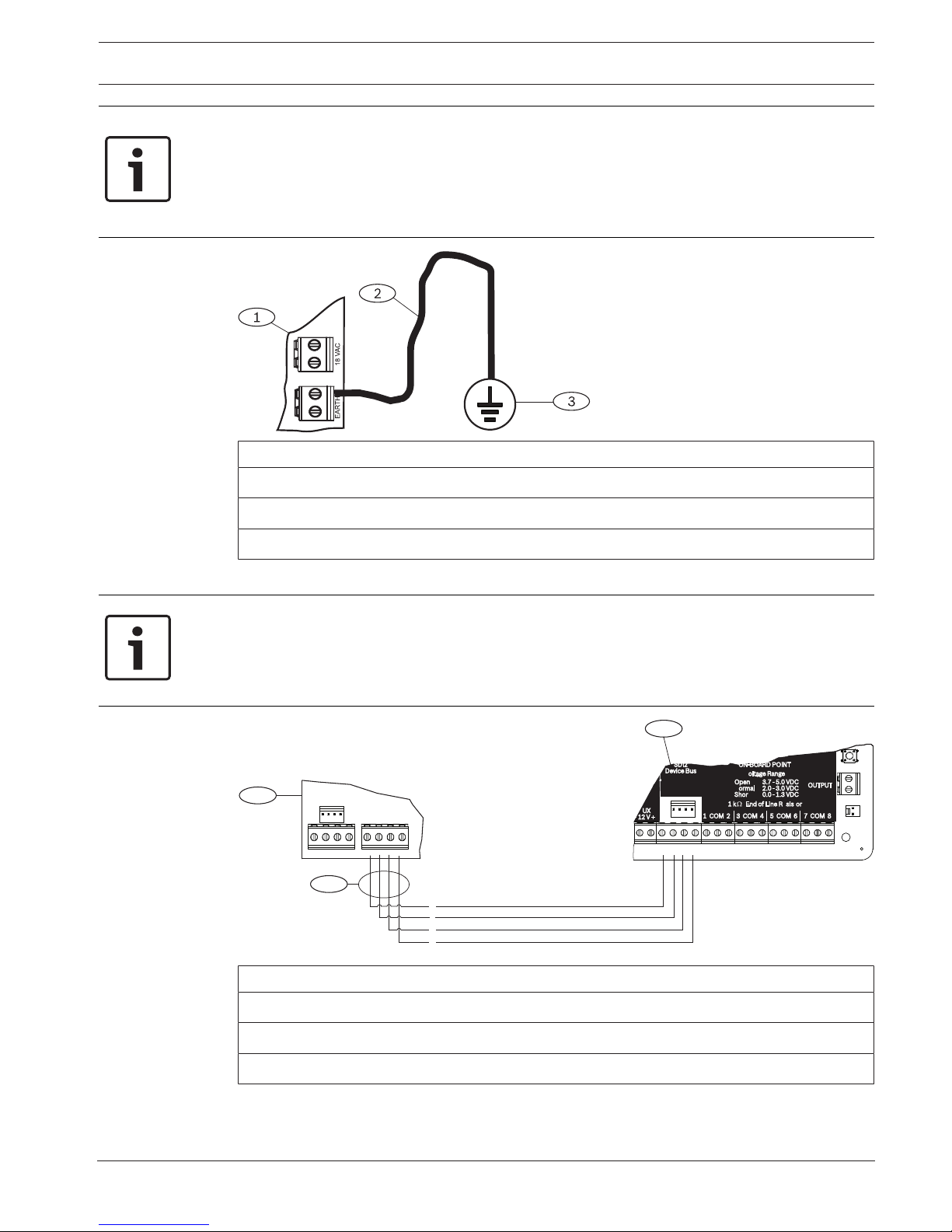
Wiring to earth ground
4 To help prevent damage from electrostatic charges or other transient electrical surges,
connect the system to earth ground before making other connections.
Control Panels Power supply | en 25
Bosch Security Systems, Inc. Installation Manual 2018.07 | 16 | F.01U.287.180
Notice!
Earth ground reference
Do not use telephone or electrical ground for the earth ground connection. Use 14 AWG (1.8
mm) to 16 AWG (1.5 mm) wire when making the connection
Use a grounding rod or a cold water pipe.
Run wire as close as possible to grounding device.
Callout ᅳ Description
1 ᅳ B520 Auxiliary Power Supply Module
2 ᅳ 14 AWG - 16 AWG (1.8 mm - 1.5 mm) wire
3 ᅳ Ground device (grounding rod or cold water pipe)
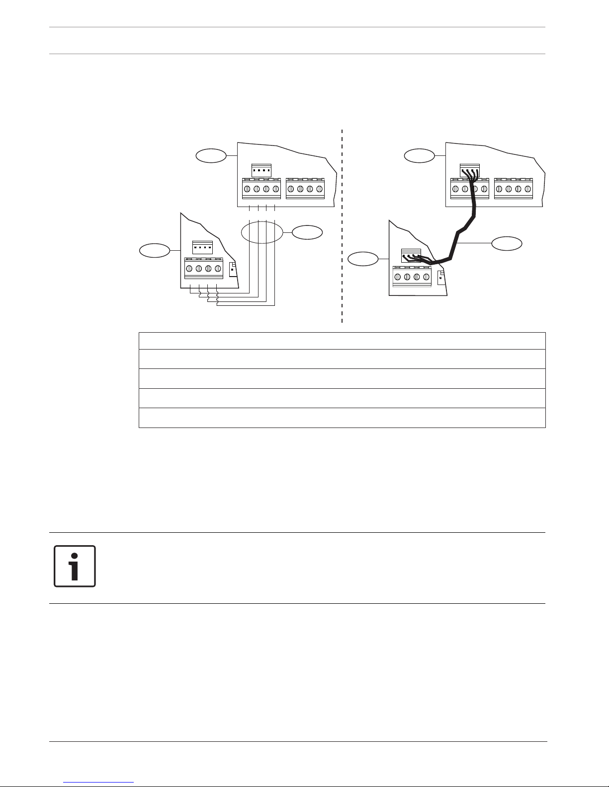
Wiring to the control panel
Notice!
Terminal wiring
Use the terminal strip labeled with PWR, A, B, and COM for SDI2 IN to wire to corresponding
control panel SDI2 terminals. Do not use interconnect wiring.
Use 12 AWG to 22 AWG (2.0 mm to 0.6 mm) wire.
SDI2 OUT
SDI2 IN
PWR A B COM PWR A B COM
1
2
3
R
Y
G
B
7 COM 8
C
OUTPUT
B
1 k End of Line Resistors
Voltage Ranges
ON-BOARD POINTS
3.7 - 5.0 VDC
2.0 - 3.0 VDC
0.0 - 1.3 VDC
Open
Normal
Short
3 COM 4 5 COM 61 COM 2
R Y G B
SDI2
Device Bus
AUX
- 12 V +
TMPR
1 COM 2 7 COM 83 COM 4 5 COM 6
RESET
COM AUX
R Y G B
PWR A B COM
B C
OUTPUT
Callout ᅳ Description
1 ᅳ Control panel
2 ᅳ B520 Auxiliary Power Supply Module
3 ᅳ Terminal strip wiring
26 en | Power supply Control Panels
2018.07 | 16 | F.01U.287.180 Installation Manual Bosch Security Systems, Inc.
6.3.5 Powered device and battery wiring
When you wire the output of a B520 to a SDI2 module, the B520 provides power to the
module while passing through data between the control panel and the module.
Wiring SDI2 modules
PWR A B COM
2
4
PWR A B COM
SDI2 OUT
SDI2 IN
PWR A B COM PWR A B COM
1
2
3
SDI2 OUT
SDI2 IN
PWR A B COM PWR A B COM
1
R Y G B
Callout ᅳ Description
1 ᅳ B520 Auxiliary Power Supply Module
2 ᅳ Powered device (SDI2 module)
3 ᅳ Terminal strip wiring
4 ᅳ Interconnect wiring (P/N: F01U079745)
1. Do one of the following:
Use terminal wiring to connect the SDI2 OUT terminal strip labeled with PWR, A, B, and
COM on the B520 to the terminals labeled PWR, A, B, and COM on the first module.
Connect an interconnect wiring cable (included) to the SDI2 OUT interconnect connector
on the B520 to the interconnect connector on the first module.
2. Connect additional modules in series with the first module.
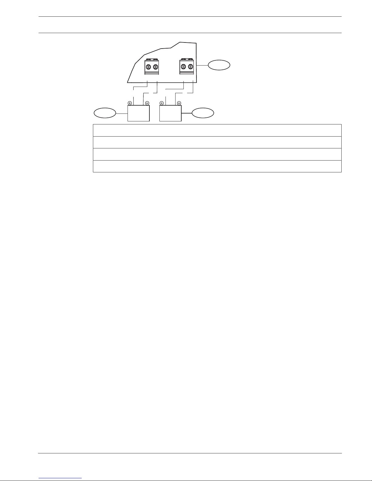
Wiring to batteries
Notice!
Battery wiring requirements
You must wire BATT 1. You must wire BATT 2 if you configure the B520 for two batteries.
When you use BATT 2, both batteries must have the same rating.
Maximum standby power cannot exceed 36 Ah.
Control Panels Power supply | en 27
Bosch Security Systems, Inc. Installation Manual 2018.07 | 16 | F.01U.287.180
BATT 1
BATT 2
R
B
R B
+ -
1
23
+ -
Callout ᅳ Description
1 ᅳ B520 Auxiliary Power Supply Module
2 ᅳ Battery 2 (BATT 2) - (12 V nominal lead acid)
3 ᅳ Battery 1 (BATT 1) - (12 V nominal lead acid)

28 en | Telephone communications Control Panels
2018.07 | 16 | F.01U.287.180 Installation Manual Bosch Security Systems, Inc.
7 Telephone communications
The control panel supports telephone (PSTN) communications with the plug-in telephone
communicator (B430).
7.1 B430 Plug-in Communicator, Telephone
The B430 provides communication over PSTN. The module provides a single telephone
interface RJ-45 connector for connecting the phone line. The module plugs directly into the
control panel with no additional connections required.
The control panel supports one plug-in module plugged directly into the control panel board.
The module plugs into a connector and is held in place with a plug-in module retention clip.
The module handle and support on top of the module hold the unit during installation.
For detailed instructions, refer to the corresponding document listed in Related
documentation, page 12.
Notification
The B430 module by Bosch Security Systems, Inc. is registered with the Federal
Communication Commission (FCC) under Part 68, for connection to the public telephone
system using an RJ31X or RJ38X phone line connection jack installed by the local telephone
company.
Do not connect registered equipment to party lines or coin-operated telephones. Notify the
local telephone company and provide the following information before connecting the control
panel to the telephone network:
– The particular line to which you connect the module
– Make (Bosch Security Systems, Inc.), model (B6512/B5512/B4512/B3512), and serial
number of the control panel
– FCC registration number: ESVAL00BB430
– Ringer eq: 0.0B
7.1.1 Supervision
The control panel supervises the phone line. You can configure the supervision time using RPS
or the Installer Services Portal programming tool (available in Europe, Middle East, Africa, and
China).
7.1.2 Installation and module wiring (B430)
Calculate power consumption
Make sure that there is enough power for the module and the other powered devices that you
want to connect to the system.
Refer to On-board outputs, page 49.
!
Caution!
Remove all power (AC and battery) before making any connections. Failure to do so might
result in personal injury and/or equipment damage.
Installing the module
1. Align the module with the on-board plug-in connector on the control panel.
2. The retention clip has a locking device to help hold the card in position. Pull the locking
device back.
3. Align the PCB metal contacts with the on-board connector.
4. Push the module into place. The retention clip snaps closed to hold the module in
position.
Control Panels Telephone communications | en 29
Bosch Security Systems, Inc. Installation Manual 2018.07 | 16 | F.01U.287.180
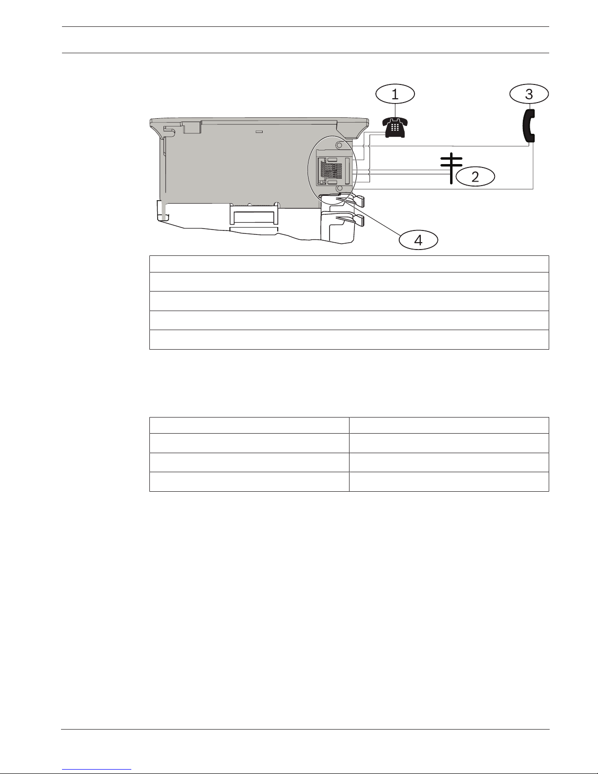
Wiring to the phone line
Callout ᅳ Description
1 ᅳ Premises telephone
2 ᅳ Incoming Telco line
3 ᅳ Installer telephone test set
4 ᅳ RJ-45 phone connector
7.1.3 Diagnostic LEDs
The module uses a green LED to show:
– Whether the module is on or off hook.
– When the line rings (incoming phone call).
Flash pattern Function
OFF Standby
ON Line seized
Flash Ringing detect (incoming phone call)
Tab.7.1: PTSN diagnostic LED patterns
7.2 Phone jack location
To prevent jamming of signals, wire the RJ31X or RJ38X jack before the premises telephone
system to support line seizure. Install the jack on the street side of the telephone switch,
wired ahead of any PBX equipment. Line seizure temporarily interrupts normal telephone use
while the control panel sends data. After installation, make sure that the control panel:
– Seizes the line
– Gets a dial tone
– Reports correctly to the receiver
– Releases the telephone line to the in-house telephone system
30 en | Telephone communications Control Panels
2018.07 | 16 | F.01U.287.180 Installation Manual Bosch Security Systems, Inc.
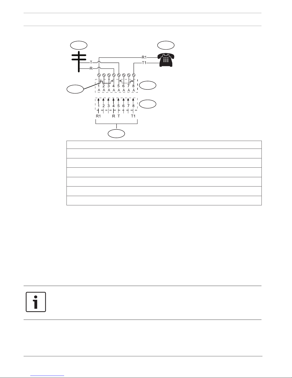
RJ31X wiring
6
4
3
5
1 2
Callout ᅳ Description
1 ᅳ Outside Telco
2 ᅳ Premises telephone
3 ᅳ Bar short removed on Telco connector block insertion – positions 1 and 4 and 5 and 8
4 ᅳ RJ31X jack
5 ᅳ Telco connector block
6 ᅳ To control panel
7.3 Telephone line monitor
The B430 module has a built-in telephone line monitor that tests the telephone line for voltage
and current. The normal voltage on a telephone line is approximately 48 VDC (24 VDC for
some telephone systems).
If the module senses trouble, it starts a programmable telephone line trouble timer, which
continues to run as long as the monitor detects trouble. It resets to zero when the control
panel senses a normal line. If the timer reaches the delay time in the Phone Supervision
program item, it begins a telephone line trouble response. Programming determines what the
response is. For programming information, refer to Phone Parameters in RPS Help or in the
Installer Services Portal programming tool (available in Europe, Middle East, Africa, and China)
Help.
Notice!
Bad line might test OK
The telephone line monitor uses voltage levels to test the status of the telephone line. In
some instances, a given telephone line might be out of service without affecting the voltage
on the line. The telephone line monitor cannot recognize this trouble condition.
7.4 Called party disconnect
Telephone companies provide “called party disconnect” to allow the called party to terminate
a call. The called party must go on hook (hang up) for a fixed interval before a dial tone is
available for a new call. This interval varies with telephone company equipment. Control panel
 Loading...