

Page 1

Contents
Online Edition for Part no. 01 40 2 962 953 – II/15
A-Z
THE BMW i3.
OWNER'S MANUAL.
BMW i.
Page 2
Online Edition for Part no. 01 40 2 962 953 – II/15
Page 3

BMW i SUSTAINABILITY.
Online Edition for Part no. 01 40 2 962 953 – II/15
AUTOMOBILITY.
REINVENTED.
Page 4
THE SUSTAINABLE PRODUCT
Online Edition for Part no. 01 40 2 962 953 – II/15
LIFE CYCLE OF BMW i.
01. DEVELOPMENT
• Redefine design principles for
purpose-built e-mobility.
• Reshape aerodynamics for less drag.
• Replace traditional materials with
recycled and renewable materials.
04. RECYCLING
• Retain used batteries as temporary
storage units, e.g. for solar energy.
• Recycle carbon bers by returning
them to the production process.
Page 5
03. UTILIZATION
Online Edition for Part no. 01 40 2 962 953 – II/15
• Recharge battery with innovative
BMW eDrive technology.
• Receive power from clean energy
producers for zero emission driving.
• Reduce CO2 emissions by 50%
throughout the product life cycle
by using energy from renewable
sources.
02. PRODUCTION
• Use clean electric power for
BMW i plants.
• Reduce energy consumption
in BMW i production.
Page 6

01. DEVELOPMENT
Online Edition for Part no. 01 40 2 962 953 – II/15
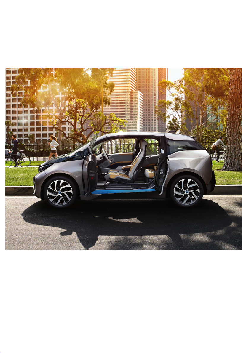
FOR OVER THREE QUARTERS OF
A CENTURY, THE BASIC IDEA BEHIND
THE CAR WAS LEFT UNTOUCHED.
Until now. Today, the BMW i3 introduces a wealth of new ways to create
the ultimate sustainable electric car. One key innovation is LifeDrive:
the rst serial production passenger cell made of light and extremely
robust carbon ber. It substantially reduces the weight of the vehicle
for maximum electric range. Moreover, streamow aerodynamics
reduce drag and energy consumption.
The interior of the BMW i3 features natural-ber based raw materials
in the instrument panel and door trim surfaces. Textiles for the seats
are made of up to 100% recycled materials. The leather components
are tanned with natural olive leaf extract, which gives the leather a
unique, fresh scent. The interior wood panels are made of open-pore
eucalyptus wood. All wood is sourced from responsible forestry and
certied by the Forest Stewardship Council® (FSC®).
Innovation is also built into the BMW i3 product development process
itself: To ensure a truly sustainable product, measurable targets were
already set in the early strategic phase of development to dene environmental guidelines for the entire product life cycle – from the sourcing
of raw materials to production, utilization and recycling. These were
agreed to and monitored throughout the development phase of the
vehicle. The life cycle assessment process and the results have been
certied by a third party according to ISO 14040/14044. Further
details can be found online at bmw-i.com.
Page 7
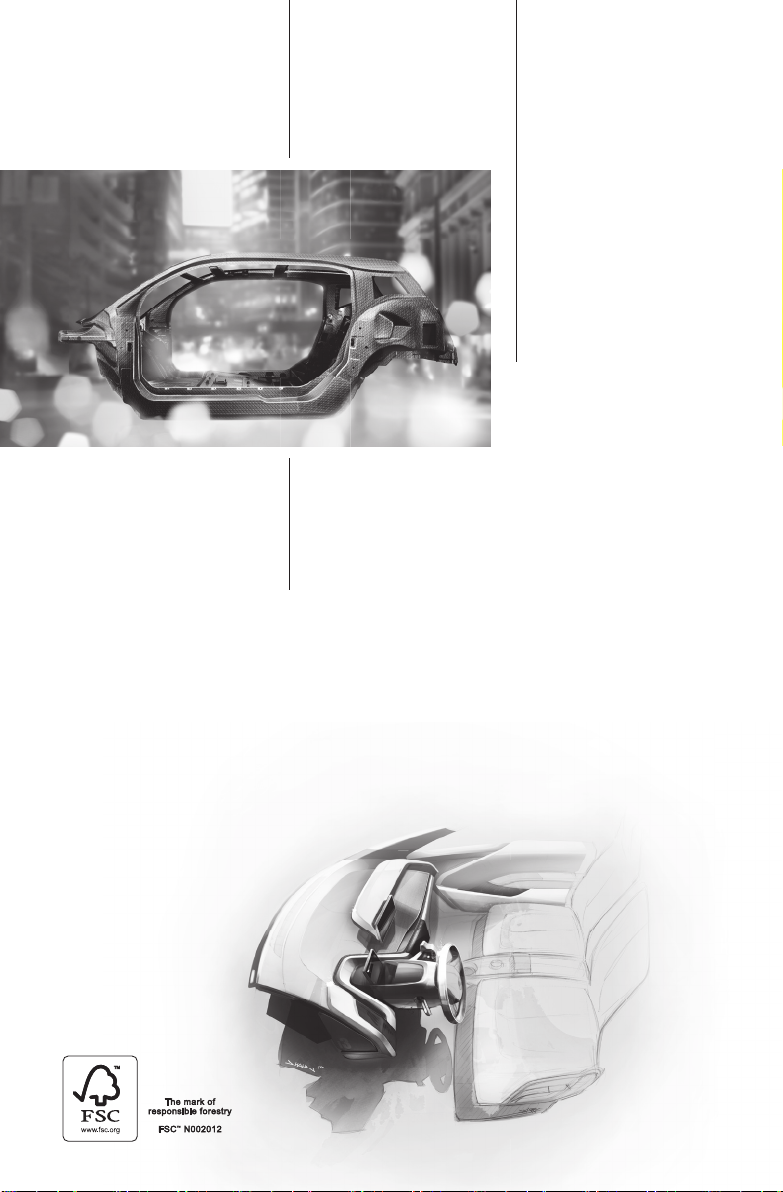
The Life module
Online Edition for Part no. 01 40 2 962 953 – II/15
is made of ultra-light
carbon ber.
%
5 0
lighter than steel.
%
30
lighter than aluminum.
The interior of the BMW i3 includes a variety
of premium-quality, sustainable materials.
Approximately 25% of the thermoplastics used
are composed of recyclates or have been
replaced by renewable materials.
Page 8

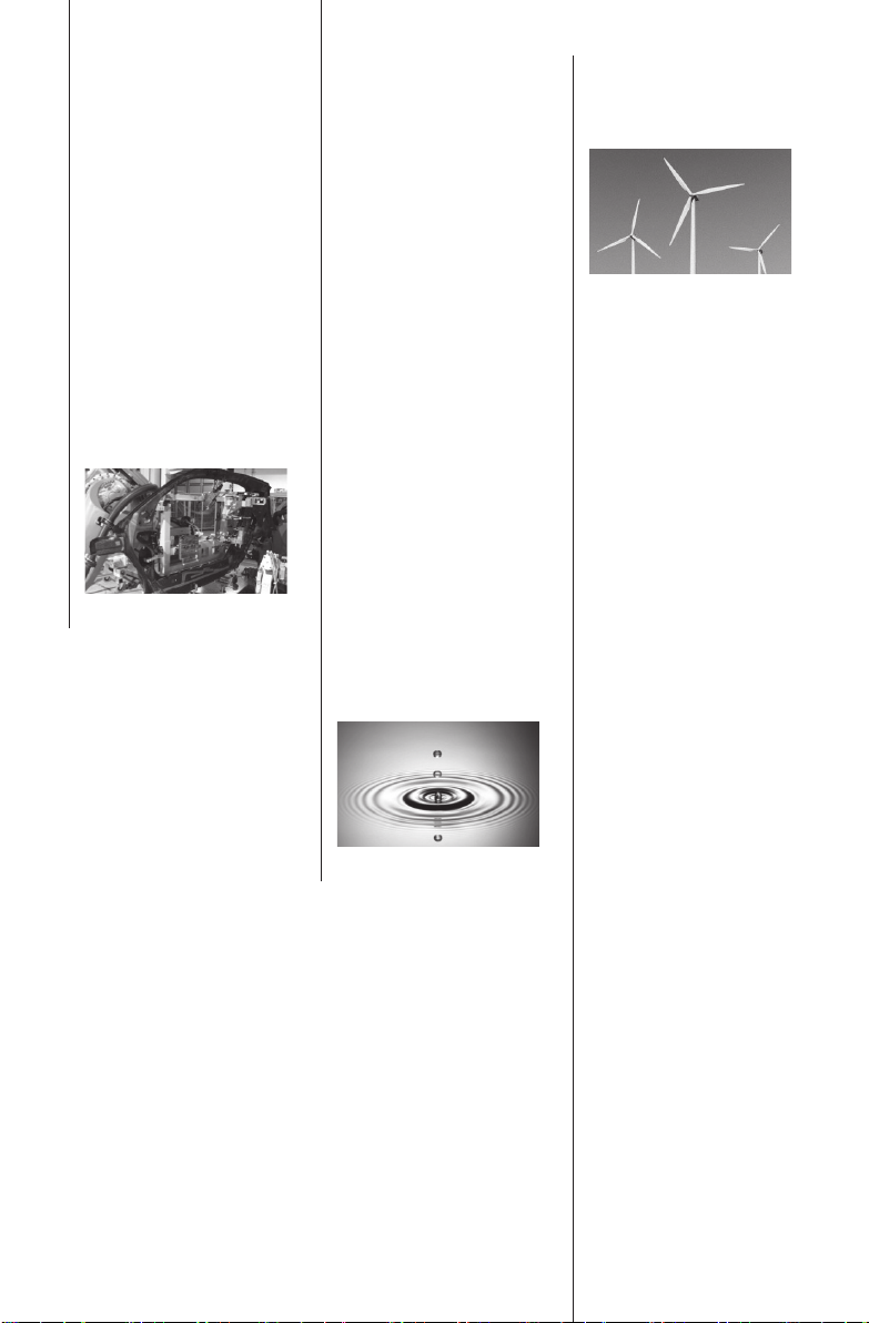
02. PRODUCTION
Online Edition for Part no. 01 40 2 962 953 – II/15
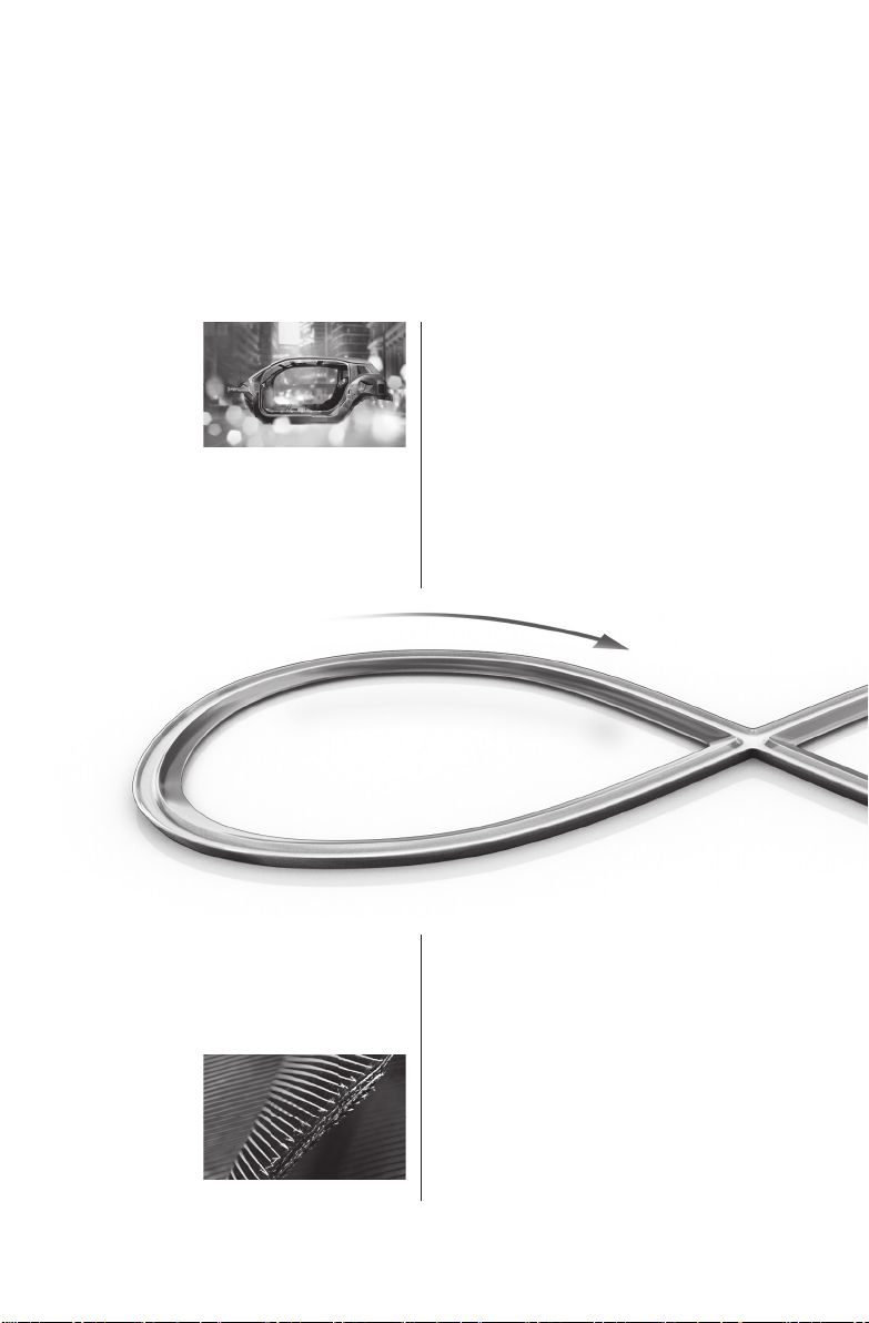
THE BMW i3: FORGED BY THE POWER
OF WIND AND WATER.
The BMW i3 not only produces zero emissions while driving; all
electricity that goes into its production in Leipzig is generated from
renewables. BMW factories have been leading the way in sustainable
production for a long time now, but BMW i has gone even further
and signicantly improved its facilities. The BMW i factory in Leipzig
produces its own renewable energy – right on the premises – and
operates on 100% clean electric power at zero emissions. It also
consumes signicantly less resources.
And consider the unique approach to carbon ber production: It has
been located in Moses Lake, USA, so that all operations can be
powered completely by renewable energy from the numerous hydroelectric plants nearby.
For BMW i, sustainable production is not only an environmental consideration but also a social one, creating future-proof job proles and
training BMW i’s suppliers to comply with advanced sustainability
standards.
Page 9
-5 0
Online Edition for Part no. 01 40 2 962 953 – II/15
energy input
%
-70
%
100
renewable energy
%
water consumption
Energy and resource
consumption per
BMW i3 produced*
* compared to the industry-
leading BMW average
Page 10

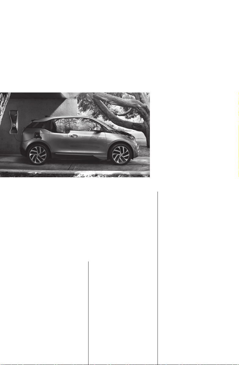
03. UTILIZATION
Online Edition for Part no. 01 40 2 962 953 – II/15
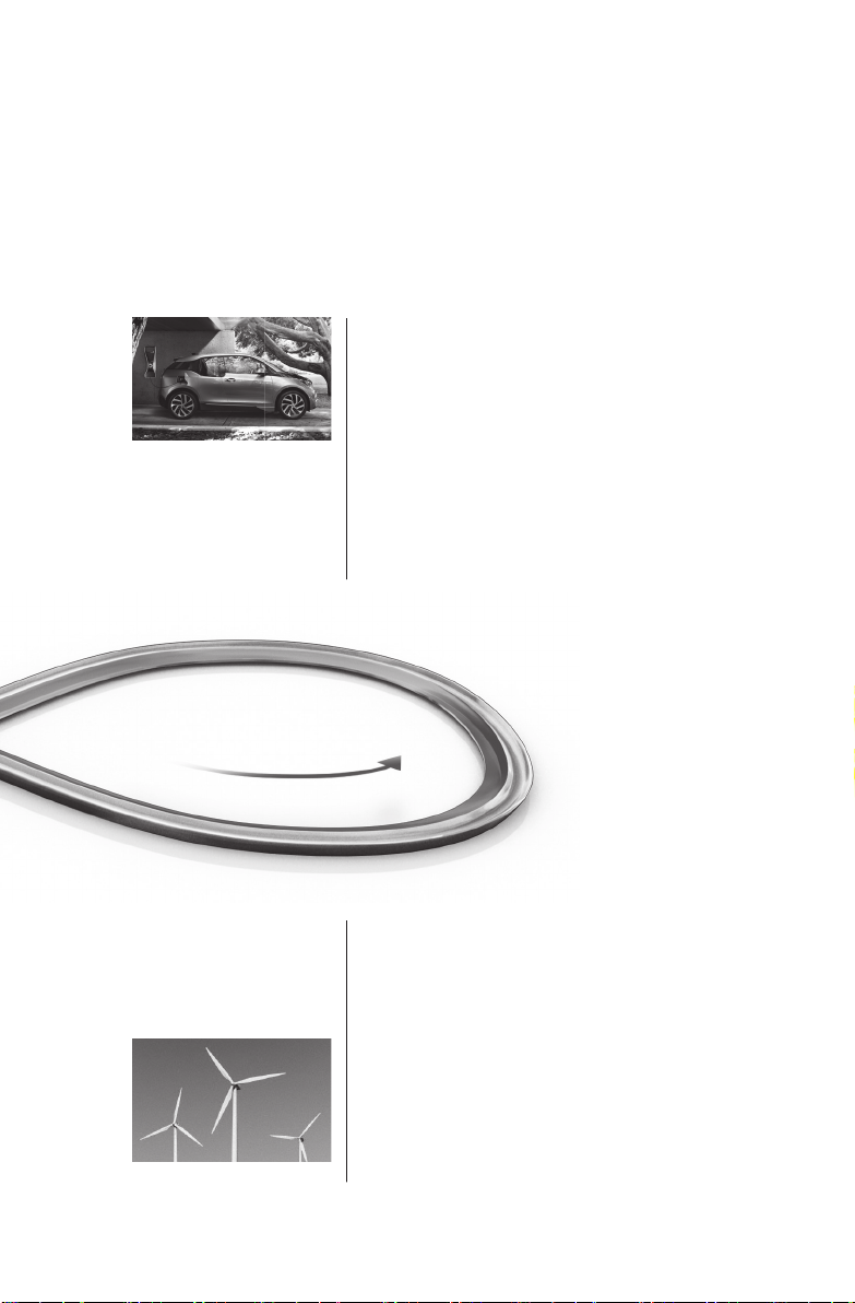
THE ORIGIN OF EMISSION-FREE
DRIVING: POWER FROM RENEWABLE
RESOURCES.
With zero local emissions while driving, the BMW i3 helps reduce air
pollution in urban areas. When charged with clean power – generated
from renewables – the positive impact is greater still. This is because,
throughout the entire product life cycle, driving the new BMW i3 on
energy from renewable sources can potentially reduce emissions (CO2
equivalents) by up to 50%, when compared to a highly efcient vehicle
of the same class with a combustion engine. That’s why BMW i recommends clean energy producers, to help make an even bigger difference. Further details can be found online at bmw-i.com/sustainability.
As if that weren’t enough, the innovative eDrive technology of the
BMW i3 also features all sorts of efciency enhancers: from state-ofthe-art brake energy recuperation to range-increasing ECO PRO+
driving mode, which can boost the driving range by up to 40km at the
touch of a button.
Page 11
In terms of its performance throughout the entire
Online Edition for Part no. 01 40 2 962 953 – II/15
product life cycle – from the sourcing of raw
materials to production, use and recycling – how
does the BMW i3 compare to a vehicle with a
high-ef ciency combustion engine?
30
fewer CO2 equivalents
when driving with
EU-25 or comparable
energy mixes.
%
%
5 0
fewer CO2 equivalents
when driving on electricity from renewable
sources.
Page 12

04. RECYCLING
Online Edition for Part no. 01 40 2 962 953 – II/15
AT BMW i WE NOT ONLY PIONEER
NEW MATERIALS, WE ALSO TAKE
CARE OF THEIR RECYCLING.
Recycling is a given at BMW i. Production residues from carbon ber
production, carbon components and body parts, for instance, are
valuable materials. That’s why they are either reused as secondary raw
materials for the in-house BMW i production cycle or recycled for other
automotive or non-automotive applications. And the early production
stage of a BMW i3 marks a rst for the automotive industry – the rst
time recycled carbon ber is being used for a vehicle passenger cell.
Together with partners, BMW i is pioneering closed loops for up to
100% of carbon ber from production residues or end-of-life vehicles.
BMW i is also branching out in new directions when it comes to the
recycling of other components and materials. For example, there are
many possible ways to reuse the high-capacity BMW i lithium ion
battery pack. A very simple and effective one is as temporary energy
storage for solar power or wind energy to make renewably produced
energy available when it is needed.
Page 13

%
Online Edition for Part no. 01 40 2 962 953 – II/15
100
of used battery
packs could, for example, be reused as
temporary storage
units for solar power
equipment and wind
energy systems.
Page 14
To nd out more about the sustainability
Online Edition for Part no. 01 40 2 962 953 – II/15
philosophy behind your BMW i, please visit:
bmw-i.com/sustainability
Page 15

Owner's Manual for Vehicle
Online Edition for Part no. 01 40 2 962 953 – II/15
i3
Thank you for choosing a BMW i.
The more familiar you are with your vehicle, the better control
you will have on the road. We therefore strongly suggest:
Read this Owner's Handbook before starting off in your new
BMW i. Also use the Integrated Owner's Manual in your vehicle.
It contains important information on vehicle operation that will
help you make full use of the technical features available in your
BMW i. The manual also contains information designed to en‐
hance operating reliability and road safety, and to contribute to
maintaining the value of your BMW i.
Any updates made after the editorial deadline can be found in
the appendix of the Owner's Handbook for Vehicle.
We wish you a safe and enjoyable ride.
BMW AG
Page 16

© 2014 Bayerische Motoren Werke
Online Edition for Part no. 01 40 2 962 953 – II/15
Aktiengesellschaft
Munich, Germany
Reprinting, including excerpts, only with the written
consent of BMW AG, Munich.
US English X/14, 11 14 490
Printed on environmentally friendly paper, bleached
without chlorine, suitable for recycling.
Page 17

Contents
Online Edition for Part no. 01 40 2 962 953 – II/15
The fastest way to find information on a partic‐
ular topic or item is by using the index, refer to
page 208.
6 Notes
At a glance
14 Cockpit
18 iDrive
26 Voice activation system
29 Integrated Owner's Manual in the vehicle
31 BMW eDRIVE
Controls
36 Opening and closing
51 Adjusting
58 Transporting children safely
62 Driving
74 Displays
89 Lights
92 Safety
106 Driving stability control systems
109 Driving comfort
127 Climate control
134 Interior equipment
138 Storage compartments
Mobility
156 Charging vehicle
165 Refueling
168 Fuel
170 Wheels and tires
179 Under the hood
181 Engine oil
183 Coolant
185 Maintenance
187 Replacing components
193 Breakdown assistance
198 Care
Reference
204 Technical data
206 Appendix
208 Everything from A to Z
Driving tips
144 Things to remember when driving
148 Loading
150 Increase range
Page 18

Notes
Online Edition for Part no. 01 40 2 962 953 – II/15
Notes
The special features of your
BMW i
High-voltage system
Your BMW i is an electric vehicle. The vehicle
features a high-voltage system that consists of
an electric motor and a high-voltage battery
among other things. Optionally, the vehicle has
a combustion engine that generates electrical
energy via a generator and thereby increases
the range. This combustion engine is called
the Range Extender.
Carbon body
The vehicle consists of two different functional
units: the drive module made from aluminum
and the life module made from carbon fiber re‐
inforced plastic (carbon).
Using this Owner's Manual
Orientation
The fastest way to find information on a partic‐
ular topic is by using the index.
An initial overview of the vehicle is provided in
the first chapter.
Symbols
Indicates precautions that must be followed
precisely in order to avoid the possibility of
personal injury and serious damage to the
vehicle.
◄ Marks the end of a specific item of
information.
Refers to measures that can be taken to
help protect the environment.
"..." Identifies display texts in vehicle used to
select individual functions.
›...‹ Verbal instructions to use with the voice
activation system.
››...‹‹ Identifies the answers generated by the
voice activation system.
Symbols on vehicle components
Indicates that you should consult the
relevant section of this Owner's Manual for
information on a particular part or assembly.
Updates made after the editorial
deadline
Any updates made after the editorial deadline
can be found in the appendix of the printed
Owner's Handbook for Vehicle.
User's manual for Navigation,
Entertainment, Communication
The topics Navigation, Entertainment, Com‐
munication and the short commands of the
voice activation system can be retrieved on the
Control Display via the Integrated Owner's
Handbook.
6
Indicates, on certain parts or assemblies, that
incorrect use of high-voltage equipment or of
orange-colored high-voltage components re‐
sults in the risk of life-threatening injury from
electric shock.
Vehicle features and options
This Owner's Manual describes all models and
all standard, country-specific and optional
Page 19

Notes
Online Edition for Part no. 01 40 2 962 953 – II/15
equipment that is offered in the model series.
Therefore, in this Owner's Manual, we also de‐
scribe and illustrate features that are not avail‐
able in your vehicle, e.g., because of the se‐
lected optional features or the country-specific
version.
This also applies to safety-related functions
and systems.
On right-hand drive vehicles, some controls
are arranged differently from what is shown in
the illustrations.
Status of the Owner's
Manual
Basic information
The manufacturer of your vehicle pursues a
policy of constant development that is con‐
ceived to ensure that our vehicles continue to
embody the highest quality and safety stan‐
dards. In rare cases, therefore, the features de‐
scribed in this Owner's Manual may differ from
those in your vehicle.
Updates made after the editorial
deadline
Any updates made after the editorial deadline
can be found in the appendix of the printed
Owner's Handbook for Vehicle.
For your own safety
there. Further information can be obtained
from your Service Centre.
Working on the vehicle, maintenance
and repairs
Advanced technology, especially the use of
high-performance high-voltage electronics
and modern materials such as carbon, requires
special knowledge when making modifications
to and working on the vehicle, as well as cus‐
tomized maintenance and repair work.
Modifications and work on the vehicle, espe‐
cially maintenance and repairs to the high-volt‐
age system and carbon body as well as the ret‐
rofitting of accessories, may only be carried
out by an authorized BMW i service center or
one that operates according to BMW i specifi‐
cations with personnel trained accordingly.
Body work and working on the high-volt‐
age system
Do not perform any modifications or work on
the vehicle, especially maintenance and repair
work on the high-voltage system and the car‐
bon body and avoid retrofitting accessories.
If work is not carried out properly, there is the
risk of fire and fatal injury from electrocution
due to the high-voltage system's high voltage.
Modifications and work on the vehicle may
only be carried out by an authorized BMW i
service center or one that operates according
to BMW i specifications with personnel trained
accordingly.◀
Warranty
Your vehicle is technically configured for the
operating conditions and registration require‐
ments applying in the country of first delivery homologation. If your vehicle is to be operated
in a different country it might be necessary to
adapt your vehicle to potentially differing oper‐
ating conditions and permit requirements. If
your vehicle does not comply with the homolo‐
gation requirements in a certain country you
cannot lodge warranty claims for your vehicle
7
Page 20

Notes
Online Edition for Part no. 01 40 2 962 953 – II/15
Parts and accessories
BMW recommends using parts and accesso‐
ries approved by BMW for this purpose.
Your BMW center is the right contact for genu‐
ine BMW parts and accessories, other prod‐
ucts approved by BMW and related qualified
advice.
BMW has tested these products for safety and
suitability in relation to BMW vehicles.
BMW can assume responsibility for them.
However, we cannot assume any responsibility
whatsoever for parts and accessories that have
not been specifically approved by BMW.
BMW cannot evaluate whether each individual
product from another manufacturer can be
used with BMW vehicles without presenting a
safety hazard. This guarantee is also not appli‐
cable when country-specific government ap‐
proval has been granted. Testing of this kind
may fail to embrace the entire range of poten‐
tial operating conditions to which components
might be exposed on BMW vehicles. Such
products could conceivably fail to comply with
BMW's own stringent quality standards.
California Proposition 65 Warning
California laws require us to state the following
warning:
Engine exhaust and a wide variety of automo‐
bile components and parts, including compo‐
nents found in the interior furnishings in a vehi‐
cle, contain or emit chemicals known to the
State of California to cause cancer and birth
defects and reproductive harm. In addition,
certain fluids contained in vehicles and certain
products of component wear contain or emit
chemicals known to the State of California to
cause cancer and birth defects or other repro‐
ductive harm. Battery posts, terminals and re‐
lated accessories contain lead and lead com‐
pounds. Wash your hands after handling. Used
engine oil contains chemicals that have caused
cancer in laboratory animals. Always protect
your skin by washing thoroughly with soap and
water.
Service and warranty
We recommend that you read this publication
thoroughly. Your vehicle is covered by the fol‐
lowing warranties:
▷ New Vehicle Limited Warranty.
▷ Rust Perforation Limited Warranty.
▷ Federal Emissions System Defect War‐
ranty.
▷ Federal Emissions Performance Warranty.
▷ California Emission Control System Lim‐
ited Warranty.
Detailed information about these warranties is
listed in the Service and Warranty Information
Booklet for US models or in the Warranty and
Service Guide Booklet for Canadian models.
Your vehicle has been specifically adapted and
designed to meet the particular operating con‐
ditions and homologation requirements in your
country and continental region in order to de‐
liver the full driving pleasure while the vehicle
is operated under those conditions. If you wish
to operate your vehicle in another country or
region, you may be required to adapt your ve‐
hicle to meet different prevailing operating
conditions and homologation requirements.
You should also be aware of any applicable
warranty limitations or exclusions for such
country or region. In such case, please contact
Customer Relations for further information.
Maintenance
Maintain the vehicle regularly to sustain the
road safety, operational reliability and the New
Vehicle Limited Warranty.
Specifications for required maintenance meas‐
ures:
▷ BMW Maintenance system
▷ Service and Warranty Information Booklet
for US models
8
Page 21

Notes
Online Edition for Part no. 01 40 2 962 953 – II/15
▷ Warranty and Service Guide Booklet for
Canadian models
If the vehicle is not maintained according to
these specifications, this could result in seri‐
ous damage to the vehicle. Such damage is
not covered by the BMW New Vehicle Limited
Warranty.
Data memory
Many electronic components on your vehicle
are equipped with data memories that tempo‐
rarily or permanently store technical informa‐
tion about the condition of the vehicle, events
and faults. This technical information generally
records the state of a component, a module, a
system or the environment:
▷ Operating mode of system components, fill
levels for instance.
▷ Status messages for the vehicle and from
its individual components, e.g., wheel rota‐
tion speed/vehicle speed, deceleration,
transverse acceleration.
▷ Malfunctions and faults in important sys‐
tem components, e.g., lights and brakes.
▷ Responses by the vehicle to special situa‐
tions such as airbag deployment or engag‐
ing the stability control system.
▷ Ambient conditions, such as temperature.
This data is purely technical in nature and is
used to detect and correct faults and to opti‐
mize vehicle functions. Motion profiles over
routes traveled cannot be created from this
data. When service offerings are used, e.g., re‐
pair services, service processes, warranty
claims, quality assurance, this technical infor‐
mation can be read out from the event and
fault memories by the service personnel, in‐
cluding the manufacturer, using special diag‐
nostic tools. You can obtain further information
there if you need it. After an error is corrected,
the information in the fault memory is deleted
or overwritten on a continuous basis.
With the vehicle in use there are situations
where you can associate these technical data
with individuals if combined with other infor‐
mation, e.g., an accident report, damage to the
vehicle, eye witness accounts — possibly with
the assistance of an expert.
Additional functions that are contractually
agreed with the customer - such as vehicle
emergency locating - you can transmit certain
vehicle data from the vehicle.
Event Data Recorder EDR
This vehicle is equipped with an event data re‐
corder EDR. The main purpose of an EDR is to
record, in certain crash or near crash-like situa‐
tions, such as an air bag deployment or hitting
a road obstacle, data that will assist in under‐
standing how a vehicle’s systems performed.
The EDR is designed to record data related to
vehicle dynamics and safety systems for a
short period of time, typically 30 seconds or
less.
The EDR in this vehicle is designed to record
such data as:
▷ How various systems in your vehicle were
operating.
▷ Whether or not the driver and passenger
safety belts were fastened.
▷ How far, if at all, the driver was depressing
the accelerator and/or brake pedal.
▷ How fast the vehicle was traveling.
These data can help provide a better under‐
standing of the circumstances in which
crashes and injuries occur.
EDR data are recorded by your vehicle only if a
nontrivial crash situation occurs; no data are
recorded by the EDR under normal driving
conditions and no personal data, e.g., name,
gender, age, and crash location, are recorded.
However, other parties, such as law enforce‐
ment, could combine the EDR data with the
9
Page 22
Notes
Online Edition for Part no. 01 40 2 962 953 – II/15
type of personally identifying data routinely ac‐
quired during a crash investigation.
To read data recorded by an EDR, special
equipment is required, and access to the vehi‐
cle or the EDR is needed. In addition to the ve‐
hicle manufacturer, other parties, such as law
enforcement, that have the special equipment,
can read the information if they have access to
the vehicle or the EDR.
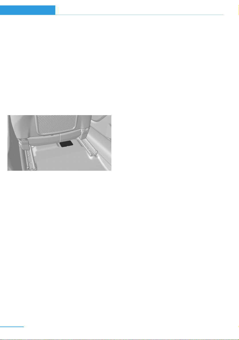
Vehicle identification
number
The vehicle identification number can be found
under a cover under the front passenger seat.
The vehicle identification number can also be
found behind the windshield.
safety defect exists in a group of vehicles, it
may order a recall and remedy campaign.
However, NHTSA cannot become involved in
individual problems between you, your dealer,
or BMW of North America, LLC.
To contact NHTSA, you may call the Vehicle
Safety Hotline toll-free at 1-888-327-4236
(TTY: 1-800-424-9153); go to http://
www.safercar.gov; or write to: Administrator,
NHTSA, 400 Seventh Street, SW., Washing‐
ton, DC 20590. You can also obtain other in‐
formation about motor vehicle safety from
http://www.safercar.gov.
For Canadian customers
Canadian customers who wish to report a
safety-related defect to Transport Canada, De‐
fect Investigations and Recalls, may call the
toll-free hotline 1-800-333-0510. You can also
obtain other information about motor vehicle
safety from http://www.tc.gc.ca/roadsafety.
Reporting safety defects
For US customers
The following only applies to vehicles owned
and operated in the US.
If you believe that your vehicle has a defect
which could cause a crash or could cause in‐
jury or death, you should immediately inform
the National Highway Traffic Safety Adminis‐
tration NHTSA, in addition to notifying BMW of
North America, LLC, P.O. Box 1227, West‐
wood, New Jersey 07675-1227, Telephone
1-800-831-1117.
If NHTSA receives similar complaints, it may
open an investigation, and if it finds that a
10
Page 23

Notes
Online Edition for Part no. 01 40 2 962 953 – II/15
11
Page 24
Online Edition for Part no. 01 40 2 962 953 – II/15
Page 25

At a glance
Online Edition for Part no. 01 40 2 962 953 – II/15
These overviews of buttons, switches and
displays are intended to familiarize you with your
vehicle. You will also become quickly acquainted
with the available control concepts and options.
Page 26
At a glance Cockpit
Online Edition for Part no. 01 40 2 962 953 – II/15
Cockpit
Vehicle features and options
This chapter describes all standard, countryspecific and optional features offered with the
series. It also describes features that are not
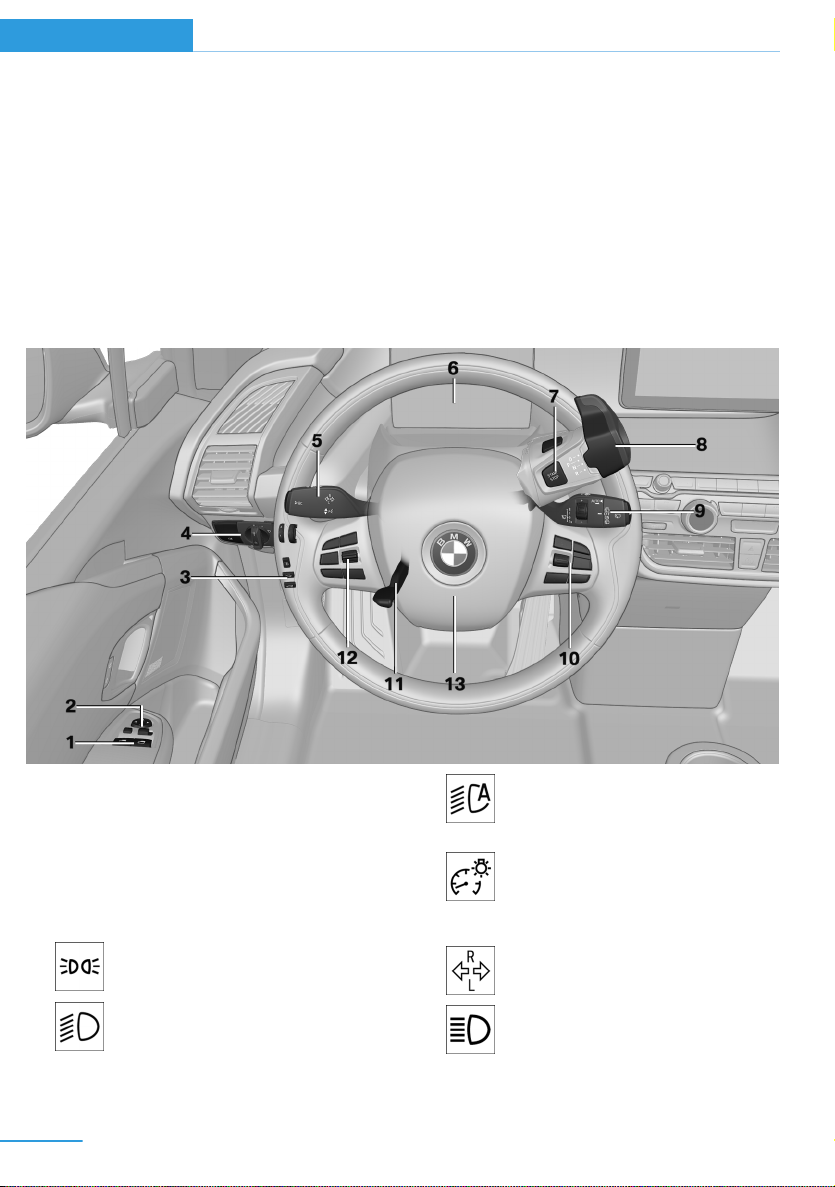
All around the steering wheel
necessarily available in your car, e. g., due to
the selected options or country versions. This
also applies to safety-related functions and
systems.
1 Power windows 48
2 Exterior mirror operation 55
3 Unlocking hood 42
Unlock tailgate 43
With Range Extender: vent fuel tank 165
4 Lights
Parking lights 89
Low beams 89
14
Automatic headlight con‐
trol 90
Daytime running lights 90
Instrument lighting 90
5 Left steering column stalk
Turn signal 69
High beams, head‐
light flasher 69
Page 27
Cockpit At a glance
Online Edition for Part no. 01 40 2 962 953 – II/15
Roadside parking lights 90
Computer 85
6 Instrument cluster 74
7 Switch drive readiness on and
off 62
8 Selector lever 64
9 Right steering column stalk
Wiper 70
Rain sensor 71
Clean the windshields and head‐
lights 71
10 Steering wheel buttons, right
Entertainment source
Volume
Voice activation 26
Telephone
Thumbwheel for selection lists 84
11 Adjust steering wheel 57
12 Steering wheel buttons, left
Store speed 115
Resume speed 117
Cruise control on/off, interrupt‐
ing 116
Active Cruise Control on/off, in‐
terrupting 109
Cruise control, adjust dis‐
tance 109
Cruise control rocker reel 116
13 Horn, total area
15
Page 28
At a glance Cockpit
Online Edition for Part no. 01 40 2 962 953 – II/15
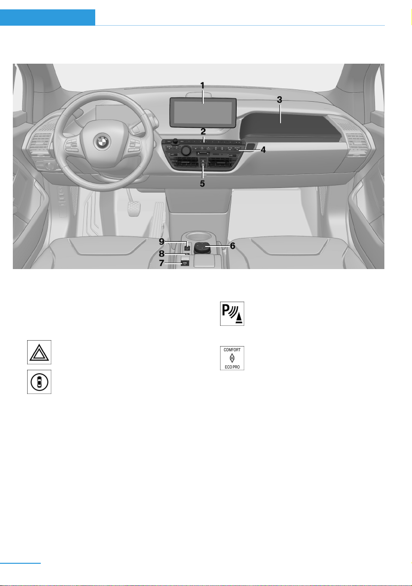
All around the center console
1 Control Display 18
2 Radio/Multimedia, refer to Integrated Own‐
er's Handbook
3 Glove compartment 138
4 Climate control 127
5 Hazard warning system 193
Intelligent Safety 99
6 Controller with buttons 18
7 Parking brake 68
8 PDC Park Distance Control 117
Rearview camera 120
Parking assistant 122
9 Driving Dynamics Control 107
16
Page 29
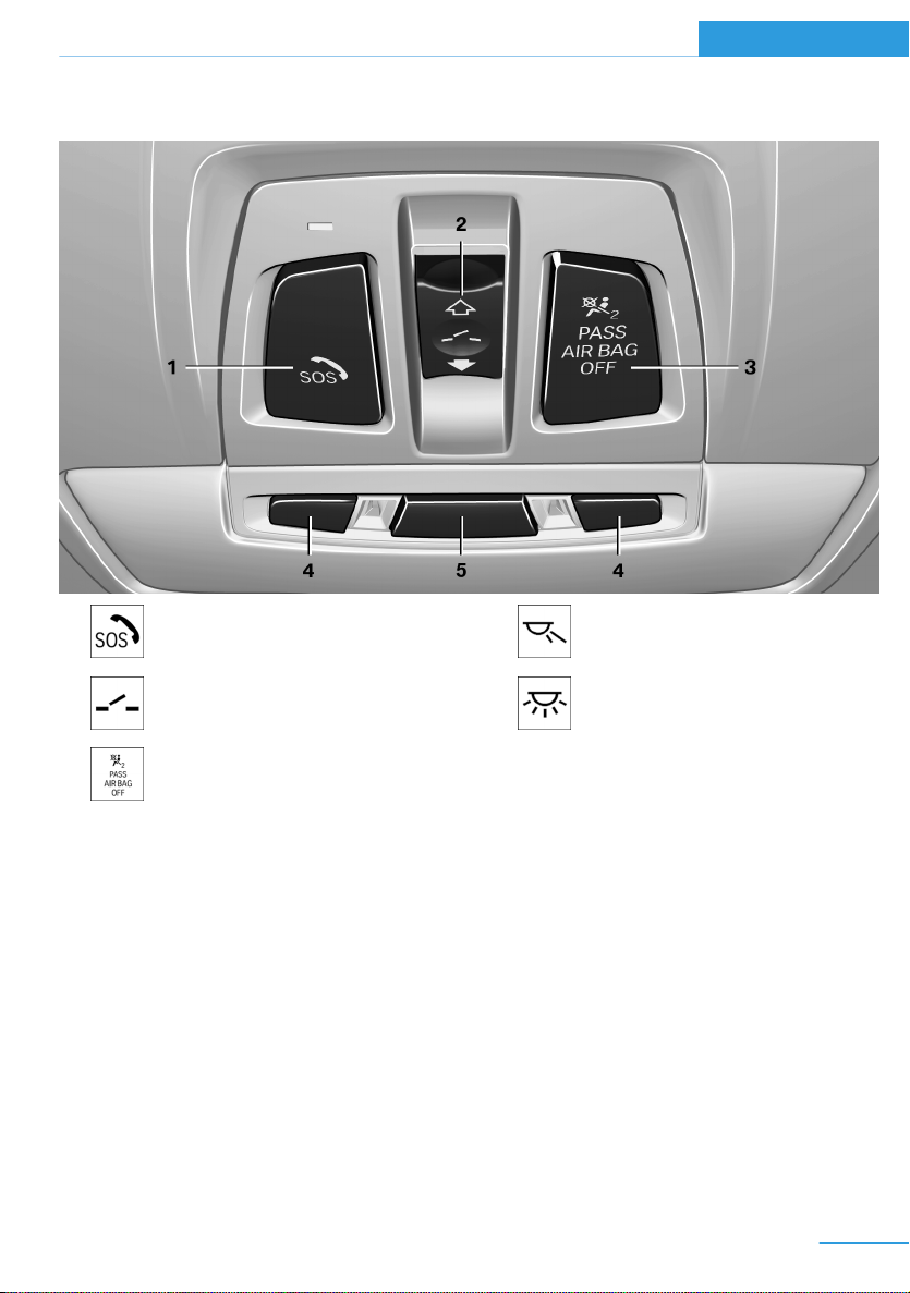
All around the roofliner
Online Edition for Part no. 01 40 2 962 953 – II/15
Cockpit At a glance
1 Intelligent Emergency Re‐
quest 193
2 Glass sunroof, powered 49
3 Indicator lamp, front-seat pas‐
senger airbag 94
4 Reading lights 91
5 Interior lights 91
17
Page 30
At a glance iDrive
Online Edition for Part no. 01 40 2 962 953 – II/15
iDrive
Vehicle features and options
This chapter describes all standard, countryspecific and optional features offered with the
series. It also describes features that are not
necessarily available in your car, e. g., due to
the selected options or country versions. This
also applies to safety-related functions and
systems.
The concept
The iDrive combines the functions of many
switches. Thus, these functions can be oper‐
ated from a central location.
Using the iDrive during a trip
To avoid becoming distracted and pos‐
ing an unnecessary hazard to your vehicle's
occupants and to other traffic, never attempt
to use the controls or enter information unless
traffic and road conditions allow it.◀
Control elements at a glance
Control Display
Hints
▷ To clean the Control Display, follow the
care instructions.
▷ Do not place objects close to the Control
Display; otherwise, the Control Display or
other surfaces can be damaged.
▷ In the case of very high temperatures on
the Control Display, e.g. due to intense so‐
lar radiation, the brightness may be re‐
duced down to complete deactivation.
Once the temperature is reduced, e.g.
through shadow or climate control system,
the normal functions are re-established.
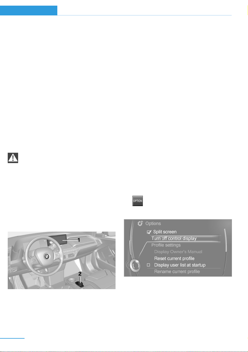
Switching on
Turn on operations.
1.
2. Press the controller.
Switch off
1. Press button.
2. "Turn off control display"
Control elements
1 Control Display
2 Controller with buttons and, depending on
the equipment version, with touchpad
18
Controller
The buttons can be used to open the menus
directly. The controller can be used to select
menu items and enter the settings.
Some iDrive functions can be operated using
the touchpad on the controller.
Page 31

iDrive At a glance
Online Edition for Part no. 01 40 2 962 953 – II/15
1. Turn.
2. Press.
3. Move in four directions.
Press button Function
BACK Displays the previous panel.
OPTION Opens the Options menu.
Operating concept
Opening the main menu
Press button.
The main menu is displayed.
All iDrive functions can be called up via the
main menu.
Buttons on controller
Press button Function
MENU Open the main menu.
RADIO Opens the Radio menu.
MEDIA Opens the Multimedia menu.
NAV Opens the Navigation menu.
TEL Opens the phone menu.
Selecting menu items
Highlighted menu items can be selected.
Turn the controller until the desired menu
1.
item is highlighted.
2. Press the controller.
19
Page 32

At a glance iDrive
Online Edition for Part no. 01 40 2 962 953 – II/15
Menu items in the Owner's Manual
In the Owner's Manual, menu items that can be
selected are set in quotation marks, e.g.,
"Settings".
Changing between panels
After a menu item is selected, e.g., "Radio", a
new panel is displayed. Panels can overlap.
▷ Move the controller to the left.
Closes current display and shows previous
display.
Reopens previous display by pressing
BACK button. In this case, the current
panel is not closed.
▷ Move the controller to the right.
Opens new display on top of previous
screen.
Additional options: move the controller to the
right repeatedly until the "Options" menu is
displayed.
Options menu
The "Options" menu consists of various areas:
▷ Screen settings, e.g., "Split screen".
This area remains unchanged.
▷ Control options for the selected main
menu, e.g., for "Radio".
▷ If applicable, further operating options for
the selected menu, e.g., "Store station".
White marks to the left or right indicate that
additional panels can be opened.
Display of an opened menu
When selecting a menu, it generally opens with
the panel that was last selected in that menu.
To display the first panel of a menu:
▷ Move the controller to the left repeatedly
until the first panel is displayed.
▷ Press the menu button on the controller
twice.
Opening the Options menu
Press button.
The "Options" menu is displayed.
20
Changing settings
Select a field.
1.
2. Turn the controller until the desired setting
is displayed.
3. Press the controller.
Activating/deactivating the functions
Several menu items are preceded by a check‐
box. It indicates whether the function is acti‐
vated or deactivated. Selecting the menu item
activates or deactivates the function.
Function is activated.
Page 33

iDrive At a glance
Online Edition for Part no. 01 40 2 962 953 – II/15
Function is deactivated.
Touchpad
Some iDrive functions can be operated using
the touchpad on the controller:
Selecting functions
1. "Settings"
2. "Touchpad"
3. Select the desired function.
▷ "Speller": enter letters and numbers.
▷ "Interactive map": viewing the interac‐
tive map.
▷ "Browser": enter Internet addresses.
▷ "Audio feedback": pronounces entered
letters and numbers.
Entering letters and numbers
Entering letters requires some practice at the
beginning. When entering, pay attention to the
following:
▷ For the input of upper/lower case letters
and numbers, it may be necessary to reel
via the controller to the corresponding In‐
put mode, refer to page 24, e.g. when the
spelling of upper and lower case letters is
identical.
▷ Enter characters as they are displayed on
the Control Display.
▷ Always enter associated characters, such
as accents or periods so that the letter can
be clearly recognized. Possible input de‐
pends on the set language. Where neces‐
sary, enter special characters via the con‐
troller.
▷ To delete a character, slide to the left on
the touchpad.
▷ To enter a blank space, slide to the right in
the center of the touchpad.
▷ To enter a hyphen, slide to the right in the
upper area of the touchpad.
▷ To enter an underscore, swipe to the right
in the lower area of the touchpad.
Using interactive map and Internet
Via touch-pad move the interactive map in the
navigation system and Internet sites.
Function Controls
Move interactive map or
Internet sites.
Enlarge/shrink interactive
map or Internet sites.
Display the menu or open
a link in the Internet.
Swipe into re‐
spective direc‐
tion.
Drag in or out on
the touchpad with
fingers.
Tap once.
Changing settings
You may change control display settings via
touchpad. Swipe left or right accordingly.
Example: setting the clock
Setting the clock
On the Control Display:
1. Press button. The main menu is dis‐
played.
2. Turn the controller until "Settings" is high‐
lighted, and then press the controller.
3. If necessary, move the controller to the left
to display "Time/Date".
21
Page 34

At a glance iDrive
Online Edition for Part no. 01 40 2 962 953 – II/15
4. Turn the controller until "Time/Date" is
highlighted, and then press the controller.
5. Turn the controller until "Time:" is high‐
lighted, and then press the controller.
6. Turn the controller to set the hours and
press the controller.
7. Turn the controller to set the minutes and
press the controller.
Status field symbols
The symbols are grouped as follows.
Radio symbols
Symbol Meaning
HD radio station is being received.
Telephone symbols
Symbol Meaning
Incoming or outgoing call.
Missed call.
Wireless network reception
strength.
Symbol flashes: network search.
Wireless network is not available.
Bluetooth is switched on.
Roaming is active.
Text message was received.
Check the SIM card.
SIM card is blocked.
Status information
Status field
The following information is displayed in the
status field at the top right:
▷ Time.
▷ Current entertainment source.
▷ Sound output, on/off.
▷ Locating the vehicle.
▷ Wireless network reception strength.
▷ Phone status.
▷ Traffic bulletin reception.
22
SIM card is missing.
Enter PIN.
Entertainment symbols
Symbol Meaning
Music collection.
Gracenote® database.
AUX-IN port.
Page 35

iDrive At a glance
Online Edition for Part no. 01 40 2 962 953 – II/15
Additional symbols
Symbol Meaning
Spoken instructions are turned off.
Check the current vehicle position.
Split screen
General information
Additional information can be displayed on the
right side of the split screen, e.g., information
from the computer.
In the divided screen view, the so-called split
screen, this information remains visible even
when you change to another menu.
Switching the split screen on and off
1. Press button.
2. "Split screen"
Selecting the display
1. Press button.
2. "Split screen"
3. Move the controller until the split screen is
selected.
4. Press the controller or select "Split screen
content".
5. Select the desired menu item.
Programmable memory
buttons
General information
The iDrive functions can be stored on the pro‐
grammable memory buttons and called up di‐
rectly, e.g., radio stations, navigation destina‐
tions, phone numbers and menu entries.
Settings are stored for the profile currently in
use.
Saving a function
Highlight the function via the iDrive.
1.
2.
Running a function
This means, e.g., that the number is dialed
when a phone number is selected.
Displaying the button assignment
Touch buttons with bare fingers. Do not wear
gloves or use objects.
The key assignment is displayed at top edge of
screen.
Press and hold the desired button,
until a signal sounds.
Press button.
The function will work immediately.
Deleting the button assignments
Press buttons 1 and 8 simultaneously for
1.
approx. five seconds.
2. "OK"
23
Page 36

At a glance iDrive
Online Edition for Part no. 01 40 2 962 953 – II/15
Deleting personal data in the
vehicle
The concept
Depending on the usage, the vehicle saves
personal data, such as stored radio stations.
These personal data can be permanently de‐
leted through iDrive.
General information
Depending on the equipment package, the fol‐
lowing data can be deleted:
▷ Personal Profile settings.
▷ Stored radio stations.
▷ Stored Favorites buttons.
▷ Travel and computer information.
▷ Music collection.
▷ Navigation, e.g. stored destinations.
▷ Phone book.
▷ Online data, e.g. Favorites, cookies.
▷ Voice notes.
▷ Login accounts.
▷ RemoteApp smartphone tethering.
Altogether, the deletion of the data can take up
to 30 minutes.
Entering letters and numbers
General information
On the Control Display:
1. Turn the controller: select letters or num‐
bers.
2. Select additional letters or numbers if
needed.
3. "OK": confirm the entry.
Symbol Function
Press the controller: delete the let‐
ter or number.
Press the controller for an extended
period: delete all letters or numbers.
Switching between cases, letters and
numbers
Depending on the menu, you can reel between
entering upper and lower case, letters and
numbers:
Symbol Function
Enter the letters.
Enter the numbers.
Functional requirement
Data can only be deleted while stationary.
Deleting data
Heed and follow the instructions on the Con‐
trol Display.
Turn on operations.
1.
2. "Settings"
3. Open "Options".
4. "Delete personal data"
5. "Continue"
6. "OK"
24
or Tip controller up.
Without navigation system
Select the symbol.
Entry comparison
Entering names and addresses: choice is nar‐
rowed down with every letter entered and let‐
ters may be added automatically.
Entries are continuously compared with data
stored in the vehicle.
▷ Only those letters are offered during input
for which data is available.
Page 37

▷ Target search: names of locations may be
Online Edition for Part no. 01 40 2 962 953 – II/15
entered in languages available through
Control Display.
iDrive At a glance
25
Page 38

At a glance Voice activation system
Online Edition for Part no. 01 40 2 962 953 – II/15
Voice activation system
Vehicle features and options
This chapter describes all standard, countryspecific and optional features offered with the
series. It also describes features that are not
necessarily available in your car, e. g., due to
the selected options or country versions. This
also applies to safety-related functions and
systems.
The concept
▷ Most functions displayed on the Control
Display can be operated by voice com‐
mands via the voice activation system. The
system supports you with announcements
during input.
▷ Functions that can only be used when the
vehicle is stationary cannot be used via the
voice activation system.
▷ The system uses a special microphone on
the driver's side.
▷ ›...‹ Verbal instructions in the Owner's
Manual to use with the voice activation
system.
Requirements
Via the Control Display, set a language that is
also supported by the voice activation system
so that the spoken commands can be identi‐
fied.
Set the language, refer to page 87.
Using voice activation
Activating the voice activation system
1.
2. Wait for the signal.
3. Say the command.
This symbol in the instrument cluster indi‐
cates that the voice activation system is active.
If no other commands are available, use func‐
tion via iDrive.
Press button on the steering
wheel.
A command that is recognized by the voice
activation system is announced and dis‐
played in the instrument cluster.
Terminating the voice activation
system
Briefly press the button on the steer‐
ing wheel or ›Cancel‹.
Possible commands
Most menu items on the Control Display can
be voiced as commands.
The available commands depend on the menu
that is currently displayed on the Control Dis‐
play.
There are short commands for many functions.
You may select lists such as phone lists via
voice activation. Read these lists out loud ex‐
actly as they show in the respective list.
26
Having possible commands read aloud
You can have available commands read out
loud for you: ›Voice commands‹
E. g. if the "Settings" menu is displayed, the
commands for the settings are read out loud.
Page 39

Voice activation system At a glance
Online Edition for Part no. 01 40 2 962 953 – II/15
Executing functions using short
commands
Execute functions on the main menu via short
commands. It almost doesn't matter which
menu item is selected, e.g., ›Vehicle status‹.
Help dialog for the voice activation
system
Calling up help dialog: ›Help‹
Additional commands for the help dialog:
▷ ›Help with examples‹: announces informa‐
tion about the current operating options
and the most important commands for
them.
▷ ›Help with voice activation‹: information
about the principle of operation for the
voice activation system is announced.
One example: open the tone
settings
Via the main menu
The commands of the menu items are spoken
just as they are selected via the controller.
Turn on the Entertainment sound output if
1.
needed.
2.
3. ›Radio‹
4. ›Tone‹
Press button on the steering
wheel.
Setting the voice dialog
Set system to standard dialog or use a short
version.
The short version of the voice dialog plays
back short messages in abbreviated form.
1. "Settings"
2. "Language/Units"
3. "Speech type:"
4. Select setting.
Adjusting the volume
Turn the volume button while giving an in‐
struction until the desired volume is set.
▷ The volume remains constant even if the
volume of other audio sources is changed.
▷ The volume is stored for the profile cur‐
rently in use.
Hints on Emergency
Requests
Do not use the voice activation system to ini‐
tiate an Emergency Request. In stressful situa‐
tions, the voice and vocal pitch can change.
This can unnecessarily delay the establish‐
ment of a phone connection.
Instead, use the SOS button, refer to
page 193, close to the interior mirror.
Via short command
The desired tone settings can also be started
via a short command.
Turn on the Entertainment sound output if
1.
needed.
2.
3. ›Tone‹
Press button on the steering
wheel.
Environmental conditions
▷ Say the commands, numbers, and letters
smoothly and with normal volume, empha‐
sis, and speed.
▷ Always say commands in the language of
the voice activation system.
▷ Keep the doors, windows, and glass sun‐
roof closed to prevent noise interference.
27
Page 40

At a glance Voice activation system
Online Edition for Part no. 01 40 2 962 953 – II/15
▷ Avoid making other noise in the vehicle
while speaking.
28
Page 41

Integrated Owner's Manual in the vehicle At a glance
Online Edition for Part no. 01 40 2 962 953 – II/15
Integrated Owner's Manual in the vehicle
Vehicle features and options
This chapter describes all standard, countryspecific and optional features offered with the
series. It also describes features that are not
necessarily available in your car, e. g., due to
the selected options or country versions. This
also applies to safety-related functions and
systems.
Integrated Owner's Manual
in the vehicle
The Integrated Owner's Manual can be dis‐
played on the Control Display. It specifically
describes features and functions found in the
vehicle.
Components of the Integrated
Owner's Manual
The Integrated Owner's Manual consists of
three parts, which offer various levels of infor‐
mation or possible access.
Quick Reference Guide
The Quick Reference Guide provides informa‐
tion how to operate the car, how to use basic
vehicle functions or what to do in case of a
breakdown. This information can also be dis‐
played while driving.
Search by images
Image search provides information and de‐
scriptions. This is helpful when the terminol‐
ogy for a feature is not at hand.
Owner's Manual
Search for information and descriptions by en‐
tering terms selected from the index.
Select components
1.
2. Turn the controller: open "Vehicle info".
3. Press the controller.
4. Selecting desired range:
Press button.
▷ "Quick reference"
▷ "Search by pictures"
▷ "Owner's Manual"
Leafing through the Owner's Manual
Page by page with link access
Turn the controller until the next or previous
page is displayed.
Page by page without link access
Scroll through the pages directly while skip‐
ping the links.
Highlight the symbol once. Now simply press
the controller to browse from page to page.
Scroll back.
Scroll forward.
29
Page 42

At a glance Integrated Owner's Manual in the vehicle
Online Edition for Part no. 01 40 2 962 953 – II/15
Context help - Owner's Manual to the
temporarily selected function
You may open the relevant information di‐
rectly.
Opening via the iDrive
To move directly from the application on the
Control Display to the Options menu:
1.
2. "Display Owner's Manual"
Press button or move the controller
to the right repeatedly until the "Options"
menu is displayed.
Opening when a Check Control
message is displayed
Directly from the Check Control message on
the Control Display:
"Display Owner's Manual"
Changing between a function and the
Owner's Manual
To reel from a function, e. g., radio, to the
Owner's Manual on the Control Display and to
alternate between the two displays:
Programmable memory buttons
General information
The Owner's Manual can be stored on the pro‐
grammable memory buttons and called up di‐
rectly.
Storing
1. "Owner's Manual" Select via the iDrive.
2.
Press selected button for more
than 2 seconds.
Executing
Press button.
The Owner's Manual is displayed im‐
mediately.
1. Press button or move the controller
to the right repeatedly until the "Options"
menu is displayed.
2. "Display Owner's Manual"
3. Select the desired page in the Owner's
Manual.
4.
5.
To alternate permanently between the last dis‐
played function and the Owner's Manual re‐
peat steps 4 & 5. Opens a new display every
time.
Press button again to return to last
displayed function.
Press button to return to the page of
the Owner's Manual displayed last.
30
Page 43

BMW eDRIVE
Online Edition for Part no. 01 40 2 962 953 – II/15
BMW eDRIVE At a glance
Vehicle features and options
This chapter describes all standard, countryspecific and optional features offered with the
series. It also describes features that are not
necessarily available in your car, e. g., due to
the selected options or country versions. This
also applies to safety-related functions and
systems.
BMW eDRIVE
At a glance
1 Vehicle battery
2 Fuel filler flap
3 High-voltage battery
4 Charging port
5 Drive unit
The concept
The vehicle can be operated completely emis‐
sions free using its electrical drive system.
The special high-voltage battery supplies the
electric motor as well as the comfort features
with power.
The high-voltage battery is charged via a
charging cable, e.g., when parked or while driv‐
ing by energy recovery.
Charging can be done especially quickly via
special power connections. However, charging
via conventional power supply - at home - is
also possible.
On the go, the energy recovery ensures that
only little energy is lost when braking.
When the vehicle decelerates, the electric mo‐
tor assumes the function of a generator and
completely or partially converts the freed up
motion energy into electrical power.
As a result the high-voltage battery is partially
recharged in order to reach maximum range.
An optional Range Extender can supply the
drive system with power and thus increase the
range of the vehicle.
Functions
Electric driving: eDRIVE
The vehicle is powered exclusively by the elec‐
tric motor. The accelerator pedal can be used
not just for acceleration, but also for decelera‐
tion. In this case, the electric motor works like
a generator and charges the high voltage bat‐
tery. With a sensible driving style, this function
can be used for especially efficient energy re‐
covery and comfortable driving, using just the
accelerator pedal.
Coasting
An especially efficient operating point is socalled coasting. In this case, the vehicle is de‐
celerated only by driving resistance and no en‐
ergy flows between high-voltage battery and
electric motor. In order to coast, depress the
accelerator pedal far enough that the mark in
the instrument cluster, refer to page 74, is
exactly in the center.
Energy recovery: CHARGE
The high-voltage battery is charged while driv‐
ing through energy recovery.
31
Page 44

At a glance BMW eDRIVE
Online Edition for Part no. 01 40 2 962 953 – II/15
The electric motor acts as a generator and
converts the kinetic energy of the vehicle into
electric current.
Charging can take place in various situations
while the vehicle is in motion:
▷ As soon as the gas pedal is only slightly
depressed.
▷ During vehicle braking.
The mark in the instrument cluster is located
within the CHARGE range.
Sensible driving and early speed reduction are
important to make full use of the energy recov‐
ery feature.
Display
The eDRIVE displays, refer to page 74, pro‐
vide information about the current state of the
drive and visualize the system's use in a dia‐
gram.
Maximize energy-saving driving and
range
Energy-saving driving is the basic prerequisite
for as large a range as possible. eDRIVE pro‐
vides various functions that assist with an en‐
ergy-saving driving style and in the process
help to monitor the range and if needed to in‐
crease it. The following instructions provide an
overview of the available functions and the per‐
sonal measures.
▷ ECO PRO routing for efficient route plan‐
ning.
▷ ECO PRO+ mode for economical driving
with limited comfort features.
▷ Charging assistant helps to find and in‐
clude public charging stations.
▷ Range assistant automatically checks the
radius of action, see Integrated Owner's
Manual.
▷ Intermodal routing for trip planning using
public transportation, refer to Integrated
Owner's Manual.
▷ Monitoring of a charging station, whose
reachability is automatically checked, see
Integrated Owner's Manual.
During driving
▷ General driving tips, refer to page 150, for
increasing the range.
▷ Use the eDRIVE system efficiently, refer to
page 144, for an optimized driving style.
▷ ECO PRO driving style analysis, refer to
page 153, for driving style analysis.
▷ ECO PRO and ECO PRO+ mode, refer to
page 151, for increasing the range.
▷ Display of the Fuel consumption history,
refer to page 76.
▷ Display of secondary functions and the po‐
tential range, refer to page 77.
Before driving
eDRIVE allows using the air conditioner even
before driving off. The stationary climate con‐
trol, refer to page 132, provides more range
than full air conditioning while driving.
Parked car ventilation during the charging
process can provide maximum range when
driving off.
Trip planning and special functions of
the navigation system
Enter your destination and the following func‐
tions will be available:
32
After the trip
▷ Charge vehicle, refer to page 156, and
plan next trip.
▷ Prepare for long downtimes, refer to
page 201.
BMW i Remote app
A special BMW i Remote App allows to control
and display certain vehicle functions using a
smartphone.
Page 45

Safety information
Online Edition for Part no. 01 40 2 962 953 – II/15
Read the information on safe handling of the
high-voltage system, refer to page 196.
Long-term
Follow the instructions for vehicle storage and
for longer idle periods, refer to page 201.
BMW eDRIVE At a glance
33
Page 46

Online Edition for Part no. 01 40 2 962 953 – II/15
Page 47

Controls
Online Edition for Part no. 01 40 2 962 953 – II/15
This chapter is intended to provide you with
information that will give you complete control of
your vehicle. All features and accessories that
are useful for driving and your safety, comfort
and convenience are described here.
Page 48

Controls Opening and closing
Online Edition for Part no. 01 40 2 962 953 – II/15
Opening and closing
Vehicle features and options
This chapter describes all standard, countryspecific and optional features offered with the
series. It also describes features that are not
necessarily available in your car, e. g., due to
the selected options or country versions. This
also applies to safety-related functions and
systems.
Remote control/key
General information
The vehicle is supplied with two remote con‐
trols with integrated key.
Every remote control holds a replaceable bat‐
tery.
You may set the key functions depending on
the optional features and country-specific ver‐
sion. For Settings, refer to page 45.
The vehicle stores personal settings for every
remote control. Personal Profile, refer to
page 37.
The remote controls hold information on re‐
quired maintenance. Service data in the re‐
mote control, refer to page 185.
3 Unlocking hood
4 ▷ With alarm system: panic mode
▷ Without panic mode:
Adjustable function: headlight courtesy
delay feature, stationary air condition‐
ing or unlock tailgate.
Integrated key
Press button on the remote control, arrow 1,
and pull out the key, arrow 2.
The integrated key fits the driver's door lock.
Replacing the battery
At a glance
1 Unlocking
2 Locking
36
Remove integrated key from remote con‐
1.
trol.
2. Raise the cover of the battery compart‐
ment, arrow 1.
3. Remove the cover of the battery compart‐
ment, arrow 2.
Page 49

Opening and closing Controls
Online Edition for Part no. 01 40 2 962 953 – II/15
4. Insert a battery of the same type with the
positive side facing up.
5. Press the cover closed.
Take the used battery to a recycling
center or to your service center.
New remote controls
New remote controls are available from the
service center.
Loss of the remote controls
Lost remote controls can be disabled by your
service center.
Emergency detection of remote
control
Also in the following situations, radio-ready
state and drive readiness can be established:
▷ Interference of radio transmission to re‐
mote control by external sources e.g., by
radio masts.
▷ Empty battery in remote control.
▷ Interference from radio transmissions
through mobile devices in close proximity
to remote control.
▷ Interference of radio transmission by
charger while charging items such as mo‐
bile devices in the vehicle.
A Check Control message is displayed if one
attempts to turn on the radio-ready state or ac‐
tivate engine readiness.
Activation of drive readiness via
emergency detection of the remote
control
If a respective Check Control message ap‐
pears, hold the remote control with its back
against the marked area on the steering col‐
umn. The BMW logo on the remote control
should be at the same height as the marked
area. Press the Start/Stop button within
10 seconds while pressing the brake pedal.
If the remote control is not recognized: slightly
change the height position of the remote con‐
trol and repeat the procedure.
Personal Profile
The concept
Individual settings in the vehicle are saved in
personal profiles. Every remote control is as‐
signed the last active profile.
Three personal profiles and a guest profile can
be created.
▷ Changes to the settings are automatically
saved in the profile currently activated.
▷ Unlocking the car activates the profile that
is stored in the remote control.
▷ Your personal settings will be recognized
and activated even if the vehicle had been
operated with another remote control.
Adjusting
The settings for the following systems and
functions are saved in the active profile. The
37
Page 50

Controls Opening and closing
Online Edition for Part no. 01 40 2 962 953 – II/15
scope of storable settings is country- and
equipment-dependable.
▷ Unlocking and locking.
▷ Lights.
▷ Climate control.
▷ Radio.
▷ Instrument cluster.
▷ Programmable memory buttons.
▷ Volumes, tone.
▷ Control Display.
▷ Navigation.
▷ Park Distance Control PDC.
▷ Rearview camera
▷ Driving Dynamics Control.
▷ Cruise control.
▷ Intelligent Safety.
Profile management
Opening profiles
Regardless of the remote control in use a dif‐
ferent profile may be activated.
"Settings"
1.
2. "Profiles"
3. Select a profile.
The activated profile is assigned to the cur‐
rently used remote control.
Resetting profiles
The settings of the active profile are reset to
their default values.
1. "Settings"
2. "Profiles"
3. "Options"
4. "Reset current profile"
Exporting profiles
Most settings of the active profile and the
saved contacts can be exported.
This can be helpful for securing and retrieving
personal settings, before delivering the vehicle
to a workshop, e.g. Profiles can be taken to an‐
other vehicle equipped with the Personal Pro‐
file function.
The following export options are available:
▷ Via BMW Online.
▷ Via the USB port to a USB device.
Popular file systems for USB devices are
supported. FAT32 and exFAT are the rec‐
ommended formats for profile export.
Other formats may not support the export.
1. "Settings"
2. "Profiles"
3. "Export profile"
4. BMW Online: "BMW Online"
USB port: "USB device"
Renaming profiles
"Settings"
1.
2. "Profiles"
3. "Options"
4. "Rename current profile"
38
Importing profiles
Profiles exported via BMW Online can also be
imported via BMW Online.
Profiles stored on a USB device can be im‐
ported via the USB interface.
Existing settings and contacts are overwritten
with the imported profile.
"Settings"
1.
2. "Profiles"
3. "Import profile"
4. BMW Online: "BMW Online"
Page 51

Opening and closing Controls
Online Edition for Part no. 01 40 2 962 953 – II/15
USB interface: "USB device"
Using the guest profile
The guest profile is for individual settings that
are saved in none of the three personal pro‐
files.
This can be useful for drivers who are using
the vehicle temporarily and do not have their
own profile.
1. "Settings"
2. "Profiles"
3. "Guest"
The guest profile cannot be renamed. It is not
assigned to the current remote control.
Display profile list during start
The profile list can be displayed during each
start to select the desired profile.
"Settings"
1.
2. "Profiles"
3. "Options"
4. "Display user list at startup"
▷ The welcome lamps are switched on, if this
function was activated.
▷ Exterior mirrors folded through convenient
closing are folded open.
You can set how the vehicle is to be unlocked.
For Settings, refer to page 45.
The alarm system, refer to page 46, is dis‐
armed.
Convenient opening
Press and hold this button on the re‐
mote control after unlocking.
The windows and the glass sunroof are
opened, as long as the button on the remote
control is pressed.
Locking
Locking from the outside
Do not lock the vehicle from the outside
with people inside the car, as the vehicle can‐
not be unlocked from inside without special
knowledge.◀
Press button on the remote control.
Using the remote control
Note
Take the remote control with you
People or animals left unattended in a
parked vehicle can lock the doors from the in‐
side. Always take the remote control with you
when leaving the vehicle so that the vehicle
can then be opened from the outside.◀
Unlocking
Press button on the remote control.
▷ All doors and the tailgate are unlocked.
▷ Interior lamps and courtesy lamps are acti‐
vated. This function is not available, if the
interior lamps were switched off manually.
All doors and the tailgate are locked.
The alarm system, refer to page 46, is armed.
Switching on interior lights and
courtesy lights
Press button on the remote control with
the vehicle locked.
This function is not available, if the interior
lamps were switched off manually.
If the button is pressed again within 10 sec‐
onds after vehicle was locked, the interior mo‐
tion sensor and tilt alarm sensor of the antitheft warning system, refer to page 47, are
turned off. After locking, wait 10 seconds be‐
fore pressing the button again.
39
Page 52

Controls Opening and closing
Online Edition for Part no. 01 40 2 962 953 – II/15
Unlocking hood
Press button on the remote control for
approx. 1 second.
Depending on the features and the country
version, it is also possible to have door un‐
locked. Create the settings, refer to page 45.
If the doors were not unlocked, the hood is
locked again as soon as it is pushed closed.
Do not place the remote control under
the hood
Take the remote control with you and do not
leave it under the hood; otherwise, the remote
control is locked inside the vehicle when the
hood is closed.◀
Without alarm system: unlocking the
tailgate
The Tailgate function must be set for the re‐
mote control button. For Settings, refer to
page 45.
Press button on the remote control for
approx. 1 second.
The tailgate opens slightly, regardless of
whether the vehicle was previously locked or
unlocked.
Depending on the features and the country
version, it is also possible to have door un‐
locked. Create the settings, refer to page 45.
If the doors were not unlocked, the tailgate is
locked again as soon as it closes.
Do not place the remote control in the
cargo area
Take the remote control with you and do not
leave it in the cargo area; otherwise, the re‐
mote control is locked inside the vehicle when
the tailgate is closed.◀
Provide edge protection
Sharp objects or those with edges can
hit the rear window while driving and damage
the heat conductors of the rear window. Pro‐
vide edge protection.◀
Without alarm system: switching the
headlamp courtesy delay feature on
The headlight courtesy delay feature function
must be set for the remote control button. For
Settings, refer to page 45.
Briefly press the button on the remote
control.
The duration can be set in the Control Display.
With alarm system: panic mode
You can trigger the alarm system if you find
yourself in a dangerous situation.
Press button on the remote control for
at least 3 seconds.
To reel off the alarm: press any button.
Malfunction
Remote control detection by the vehicle can
among others be malfunctioning under the fol‐
lowing circumstances:
▷ Interference of the radio connection from
transmission towers or other equipment
with high transmit power.
▷ Shielding of the remote control due to
metal objects.
▷ Interference of the radio connection from
mobile phones or other electronic devices
in direct proximity.
Do not transport the remote control together
with metal objects or electronic devices.
In the case of interference, the vehicle can also
be unlocked and locked from the outside with‐
out remote control, refer to page 41.
40
Page 53

Opening and closing Controls
Online Edition for Part no. 01 40 2 962 953 – II/15
For US owners only
The transmitter and receiver units comply with
part 15 of the FCC/Federal Communication
Commission regulations. Operation is gov‐
erned by the following:
FCC ID:
▷ LX8766S.
▷ LX8766E.
▷ LX8CAS.
▷ LX8CAS2.
▷ MYTCAS4.
Compliance statement:
This device complies with part 15 of the FCC
Rules. Operation is subject to the following
two conditions:
▷ This device may not cause harmful inter‐
ference, and
▷ this device must accept any interference
received, including interference that may
cause undesired operation.
Any unauthorized modifications or changes to
these devices could void the user's authority to
operate this equipment.
The other doors must be unlocked or locked
from the inside.
1. Remove lid on the door lock.
To do this, slide the integrated key into the
opening from below and unlock the lid.
2. Unlock or lock door lock.
Without remote control
From the outside
Locking from the outside
Do not lock the vehicle from the outside
with people inside the car, as the vehicle can‐
not be unlocked from inside without special
knowledge.◀
Remove the key before pulling the door
handle
Before pulling the outside door handle, remove
the key to avoid damaging the paintwork and
the key.◀
Unlock or lock the driver's door via the door
lock using the integrated key, refer to page 36.
Alarm system
The alarm system is not armed if the vehicle is
locked with the integrated key.
The alarm system is triggered when the door is
opened, if the vehicle was unlocked via the
door lock.
In order to terminate this alarm, unlock vehicle
with the remote control or establish radioready state, if needed, through emergency de‐
tection of the remote control, refer to page 37.
41
Page 54

Controls Opening and closing
Online Edition for Part no. 01 40 2 962 953 – II/15
From the inside
Unlocking and locking
Via the buttons for the central locking system.
▷
▷
The vehicle is not secured against theft when
locking.
The vehicle locks automatically after you drive
off.
In the event of a severe accident, the vehicle is
automatically unlocked. The hazard warning
system and interior lights come on.
By pressing the button, the vehicle
is locked with the doors closed.
Pressing the button unlocks the
vehicle.
Unlocking and opening
▷ Press the central locking system
button to unlock the doors to‐
gether, and then pull the door handle
above the armrest.
▷ Pull the door opener on the door to be
opened. The other door remain locked.
Rear doors
The rear doors can only be opened using the
handle on the inside, arrow. The correspond‐
ing front door must be opened.
To better reach the front door's handle fold the
front seat's backrests, refer to page 52,
down.
Before exiting the vehicle, make sure that the
front safety belt is completely wound up.
When closing, make sure that the correspond‐
ing front door is far enough open.
Hood
Opening from the outside
Press button on the remote control for
approx. 1 second.
The hood is unlocked and slightly raised.
As the case may be, the doors are also un‐
locked. Unlocking with the remote control, re‐
fer to page 40.
Opening from the inside
With the vehicle is stationary, press
the button in the driver's footwell.
42
The hood is unlocked and slightly raised.
Page 55

Opening and closing Controls
Online Edition for Part no. 01 40 2 962 953 – II/15
Manual opening
For example, in case of an electrical malfunc‐
tion.
1. Remove cover underneath the unlock but‐
tons.
2. Remove wire cable and pull it back.
The hood is unlocked.
Tailgate
Opening
The tailgate swings back and up when it
opens.
Ensure that adequate clearance is available
before opening.
Opening from the outside
The Tailgate function must be set for the
remote control button. For Settings, refer
to page 45.
As the case may be, the doors are also un‐
locked. Unlocking with the remote control,
refer to page 40.
The tailgate is unlocked and can be swung up‐
ward.
Opening from the inside
With the vehicle is stationary, press
the button in the driver's footwell.
Closing
Hints
Keep the closing path clear
Make sure that the closing path of the
tailgate is clear; otherwise, injuries may re‐
sult.◀
Do not place the remote control in the
cargo area
Take the remote control with you and do not
leave it in the cargo area; otherwise, the re‐
mote control is locked inside the vehicle when
the tailgate is closed.◀
Provide edge protection
Sharp objects or those with edges can
hit the rear window while driving and damage
the heat conductors of the rear window. Pro‐
vide edge protection.◀
▷ Press button next to the tailgate.
▷ Without alarm system: press but‐
ton on the remote control for ap‐
prox. 1 second.
43
Page 56

Controls Opening and closing
Online Edition for Part no. 01 40 2 962 953 – II/15
Closing
Recessed grips on the inside trim of the tail‐
gate can be used to conveniently pull down the
tailgate.
Comfort Access
The concept
The vehicle can be accessed without activat‐
ing the remote control.
All you need to do is to have the remote con‐
trol with you, such as in your pants pocket.
The vehicle automatically detects the remote
control when it is in close proximity or in the
car's interior.
Comfort Access supports the following func‐
tions:
▷ Unlocking/locking of the vehicle.
▷ Convenient closing.
▷ Separate unlocking of the tailgate.
▷ Establish drive readiness.
Functional requirements
▷ There are no external sources of interfer‐
ence nearby.
▷ To lock the vehicle, the remote control
must be located outside of the vehicle.
▷ The next unlocking and locking cycle is not
possible until after approx. 2 seconds.
▷ Drive readiness can only be established if
the remote control is in the vehicle.
Unlocking
Grasp the door handle on the driver's or front
passenger door completely, arrow.
This corresponds with pressing the button on
the remote control.
Locking
Touch the surface on the door handle of the
driver's or front passenger door, arrow, with
your finger for approx. 1 second without grasp‐
ing the door handle.
This corresponds with pressing the button on
the remote control.
To save battery power, ensure that all power
consumers are turned off before locking the
vehicle.
Convenient closing
Monitor closing
Monitor closing to ensure that no one
becomes trapped.◀
44
Page 57

Touch the surface on the door handle of the
Online Edition for Part no. 01 40 2 962 953 – II/15
driver's or front passenger door, arrow, with
your finger and hold it there without grasping
the door handle.
This corresponds to pressing and holding
the remote control button.
In addition to locking, the windows and the
glass sunroof close and the exterior mirrors
fold in.
Unlocking the tailgate separately
Press button on tailgate's exterior
Without alarm system: This corresponds with
pressing the button on the remote control
, if the tailgate function is set.
The situation of the doors does not change.
Note the opening height of the tailgate
The tailgate swings back and up when it
opens. Ensure that there is sufficient clearance
when the tailgate opens; otherwise, damage
may result.◀
Do not place the remote control in the
cargo area
Take the remote control with you and do not
leave it in the cargo area; otherwise, the re‐
mote control is locked inside the vehicle when
the tailgate is closed.◀
Malfunction
Remote control detection by the vehicle can
among others be malfunctioning under the fol‐
lowing circumstances:
Opening and closing Controls
▷ Interference of the radio connection from
transmission towers or other equipment
with high transmit power.
▷ Shielding of the remote control due to
metal objects.
▷ Interference of the radio connection from
mobile phones or other electronic devices
in direct proximity.
Do not transport the remote control together
with metal objects or electronic devices.
In the case of a malfunction, unlock and lock
the vehicle using the buttons of the remote
control or using the integrated key, refer to
page 41.
Adjusting
Unlocking
The settings are saved in the active profile, re‐
fer to page 37.
Doors
"Settings"
1.
2. "Doors/key"
3. Select the symbol.
4. Select the desired function:
▷ "Driver's door only"
Only the driver's door is unlocked.
Pressing again unlocks the entire vehi‐
cle.
▷ "All doors"
The entire vehicle is unlocked.
Hood
Depending on optional features and country
version, this setting is not offered in some
cases.
"Settings"
1.
2. "Doors/key"
45
Page 58

Controls Opening and closing
Online Edition for Part no. 01 40 2 962 953 – II/15
3. Select the symbol.
4. Select the desired function:
▷ "Front compartment lid"
The hood is unlocked.
▷ "Front lid and door(s)"
The hood and the doors are unlocked.
Without alarm system: tailgate
Depending on optional features and country
version, this setting is not offered in some
cases.
"Settings"
1.
2. "Doors/key"
3. Select the symbol.
4. Select the desired function:
▷ "Tailgate"
The tailgate is unlocked.
▷ "Tailgate + door(s)"
The tailgate and the doors are un‐
locked.
Confirmation signals from the vehicle
The settings are saved in the active profile, re‐
fer to page 37.
"Settings"
1.
2. "Doors/key"
3. Deactivate or activate the desired confir‐
mation signals.
▷ "Acoustic sig. lock/unlock"
▷ "Flash when lock/unlock"
Automatic locking
The settings are saved in the active profile, re‐
fer to page 37.
"Settings"
1.
2. "Doors/key"
3. Select the desired function:
▷ "Lock if no door is opened"
The vehicle locks automatically after a
short period of time if no door is
opened.
Without alarm system: headlamp
courtesy delay feature/standing
climate control
The settings are saved in the active profile, re‐
fer to page 37.
1. "Settings"
2. "Doors/key"
3. Select the symbol.
4. Select the desired function:
▷ "Pathway lighting"
Headlight courtesy delay feature
▷ "Comfort climate control"
Stationary climate control
Alarm system
The concept
When the vehicle is locked, the vehicle alarm
system responds to:
▷ Opening a door, the hood or the tailgate.
▷ Movements in the interior.
▷ Changes in the vehicle tilt, e. g., during at‐
tempts at stealing a wheel.
▷ Disconnected battery voltage.
The alarm system briefly signals tampering:
▷ By sounding an acoustic alarm.
▷ By switching on the hazard warning sys‐
tem.
▷ By flashing the daytime running lights.
Arming and disarming the alarm
system
When you unlock or lock the vehicle, either
with the remote control or via the Comfort Ac‐
cess, the alarm system is disarmed or armed at
the same time.
46
Page 59

Opening and closing Controls
Online Edition for Part no. 01 40 2 962 953 – II/15
Door lock and armed alarm system
The alarm system is triggered when the door is
opened, when the vehicle is unlocked via the
door lock.
Tailgate and armed alarm system
The tailgate can be opened even when the
alarm system is armed.
After the tailgate is closed, it is locked and
monitored again when the doors are locked.
The hazard warning system flashes once.
Panic mode
You can trigger the alarm system if you find
yourself in a dangerous situation.
Press button on the remote control for
at least 3 seconds.
To reel off the alarm: press any button.
Indicator lamp on the interior rearview
mirror
▷ The indicator lamp flashes briefly every
2 seconds:
The system is armed.
▷ The indicator lamp flashes after locking:
The doors, hood or tailgate is not closed
properly, but the rest of the vehicle is se‐
cured.
After 10 seconds, the indicator lamp
flashes continuously. Interior motion sen‐
sor and tilt alarm sensor are not active.
When the still open access is closed, inte‐
rior motion sensor and tilt alarm sensor will
be switched on.
▷ The indicator lamp goes out after unlock‐
ing:
The vehicle has not been tampered with.
▷ The indicator lamp flashes after unlocking
until the radio-ready state is switched on,
but no longer than approx. 5 minutes:
An alarm has been triggered.
Tilt alarm sensor
The tilt of the vehicle is monitored.
The alarm system responds in situations such
as attempts to steal a wheel.
Interior motion sensor
The windows and glass sunroof must be
closed for the system to function properly.
Avoiding unintentional alarms
The tilt alarm sensor and interior motion sen‐
sor can be switched off together, such as in
the following situations:
▷ In automatic car washes.
▷ In duplex garages.
▷ During transport on trains carrying vehi‐
cles, at sea or on a trailer.
▷ With animals in the vehicle.
Switching off the tilt alarm sensor and
interior motion sensor
Press the remote control button again
within 10 seconds as soon as the vehicle
is locked.
The indicator lamp lights up for approx. 2 sec‐
onds and then continues to flash.
The tilt alarm sensor and interior motion sen‐
sor are turned off, until the vehicle is locked
again.
47
Page 60

Controls Opening and closing
Online Edition for Part no. 01 40 2 962 953 – II/15
Switching off the alarm
▷ Unlock vehicle with the remote control or
establish radio-ready state, if needed
through emergency detection of remote
control, refer to page 37.
▷ With Comfort Access: If you are carrying
the remote control on your person, grasp
the driver side or front passenger side door
handle completely.
Power windows
General information
Take the remote control with you
Take the remote control with you when
leaving the vehicle so that children, e.g., can‐
not operate the power windows and injure
themselves.◀
Opening
▷
▷
See also: Convenient opening, refer to
page 39, via remote control.
Press the button to the resistance
point.
The window opens while the reel is held.
Press the reel beyond the resistance
point.
The window opens automatically. Pressing
the reel again stops the motion.
Closing
Keep the closing path clear
Monitor closing and make sure that the
closing path of the window is clear; otherwise,
injuries may result.◀
▷
▷
See also: closing by means of Comfort Access,
refer to page 44.
Pull the reel to the resistance point.
The window closes while the reel is held.
Pull the reel beyond the resistance
point.
The window closes automatically. Pulling
again stops the motion.
Pinch protection system
Danger of jamming even with pinch pro‐
tection
Even with the pinch protection system, check
that the window's closing path is clear; other‐
wise, the closing action may not stop in certain
situations, e.g., if thin objects are present.◀
No window accessories
Do not install any accessories in the win‐
dow's range of movement; otherwise, the
pinch protection system will be impaired.◀
If closing force exceeds a specific margin as a
window closes, closing is interrupted.
The window reopens slightly.
Closing without the pinch protection
system
Keep the closing path clear
Monitor closing and make sure that the
closing path of the window is clear; otherwise,
injuries may result.◀
48
Page 61

Opening and closing Controls
Online Edition for Part no. 01 40 2 962 953 – II/15
E.g. danger from the outside or ice might pre‐
vent window from closing properly - proceed
as follows:
1. Pull the reel past the resistance point and
hold it there.
The pinch protection is limited and the
window reopens slightly if the closing force
exceeds a certain margin.
2. Pull the reel past the resistance point again
within approx. 4 seconds and hold it there.
The window closes without jam protection.
Glass sunroof, powered
General information
The glass sunroof is operational when the igni‐
tion is switched on.
Keep the closing path clear
Monitor closing and make sure that the
closing path of the glass sunroof is clear; oth‐
erwise, injuries may result.◀
Take the remote control with you
Take the remote control with you when
leaving the vehicle so that children, e.g., can‐
not operate the glass sunroof and injure them‐
selves.◀
Tilting the glass sunroof
Push switch briefly upward.
▷ The closed glass sunroof is
tilted.
▷ The opened glass sunroof
closes until it is in its tilted
position. The sliding visor
does not move.
Opening/closing the glass sunroof and
sliding visor together
▷ Press the reel in the desired
direction to the resistance
point and hold it there.
The glass sunroof moves as
long as the reel is held
down.
▷ Press the reel in the desired direction past
the resistance point.
The glass sunroof moves automatically.
Pressing the reel upward stops the motion.
▷ Open and close the sliding visors manually.
Additional options:
▷ Convenient opening, refer to page 39, via
the remote control.
▷ Closing by means of Comfort Access, refer
to page 44.
Comfort position
If the glass sunroof is not automatically com‐
pletely opened, the comfort position has been
attained. In this position the wind noises in the
interior are the least.
If desired, continue the movement by pressing
the reel.
Pinch protection system
If the glass sunroof while closing exceeds a
certain value, the closing operation is inter‐
rupted at roughly the center of the roof open‐
ing.
49
Page 62

Controls Opening and closing
Online Edition for Part no. 01 40 2 962 953 – II/15
The glass sunroof reopens slightly.
Danger of jamming even with pinch pro‐
tection
Despite the pinch protection system, check
that the glass sunroof's closing path is clear;
otherwise, the closing action may not be inter‐
rupted in certain extreme situations, such as
when thin objects are present.◀
Closing from the open position
without pinch protection
E. g. if there is an external danger, proceed as
follows:
Press the reel forward beyond the resist‐
1.
ance point and hold.
The pinch protection is limited and the
glass sunroof reopens slightly if the closing
force exceeds a certain margin.
2. Press the reel forward again beyond the re‐
sistance point and hold until the glass sun‐
roof closes without jam protection. Make
sure that the closing area is clear.
Closing from the raised position
without pinch protection
If there is an external danger, push the reel for‐
ward past the resistance point and hold it.
The glass sunroof closes without jam protec‐
tion.
Keep the closing path clear
Monitor closing and make sure that the
closing path of the glass sunroof is clear; oth‐
erwise, injuries may result.◀
Press the reel up and hold it until
the initialization is complete:
▷ Initialization begins within
15 seconds and is com‐
pleted when the glass sun‐
roof is completely closed.
▷ The glass sunroof closes without jam pro‐
tection.
Initializing after a power failure
After a power failure during the opening or
closing process, the glass sunroof can only be
operated to a limited extent.
Initializing the system
The system can be initialized when the vehicle
is stationary and drive readiness is established.
During the initialization, the glass sunroof
closes without jam protection.
50
Page 63

Adjusting
Online Edition for Part no. 01 40 2 962 953 – II/15
Adjusting Controls
Vehicle features and options
This chapter describes all standard, countryspecific and optional features offered with the
series. It also describes features that are not
necessarily available in your car, e. g., due to
the selected options or country versions. This
also applies to safety-related functions and
systems.
Sitting safely
The ideal seating position can make a vital
contribution to relaxed, fatigue-free driving.
The seating position plays an important role in
an accident in combination with:
▷ Safety belts, refer to page 53.
▷ Head restraints, refer to page 54.
▷ Airbags, refer to page 92.
Seats
Hints
Do not adjust the seat while driving
Do not adjust the driver's seat while driv‐
ing, or the seat could respond with unexpected
movement and the ensuing loss of vehicle
control could lead to an accident.◀
Keep the movement area unobstructed
When changing the seat position, keep
the seat's area of movement unobstructed;
otherwise, people might get injured or objects
damaged.◀
Adjusting seats
At a glance
1 Forward/backward 51
2 Height 52
3 Backrest tilt 52
Forward/backward
Do not incline the backrest too far to the
rear
Also on the front passenger side, do not incline
the backrest on the front passenger side too
far to the rear while driving, or there is a risk of
slipping under the safety belt in the event of an
accident. This would eliminate the protection
normally provided by the belt.◀
Pull the lever and slide the seat in the desired
direction.
After releasing the lever, move the seat for‐
ward or back slightly making sure it engages
properly.
51
Page 64

Controls Adjusting
Online Edition for Part no. 01 40 2 962 953 – II/15
Height
Pull the lever and apply your weight to the seat
or lift it off, as necessary.
Backrest tilt
Pull the lever and apply your weight to the
backrest or lift it off, as necessary.
Fold down seat back
1. Pull lever up to the stop.
2. Fold backrest forward.
Backrest returns to its initial position after re‐
lease.
Front seat heating
Backrest
Note
Folding back and locking the backrest
Before driving off, fold back and lock the
backrests; otherwise, an unexpected seat
movement may cause an accident.◀
52
Switching on
Press button once for each tempera‐
ture level.
The maximum temperature is reached when
three LEDs are lit.
If the journey is continued within approx. 15
minutes, the seat heating is activated automat‐
ically with the temperature selected last.
If ECO PRO+, refer to page 151, is activated,
the seat heating is deactivated.
Switch off
Press button longer.
The LEDs go out.
Page 65

Adjusting Controls
Online Edition for Part no. 01 40 2 962 953 – II/15
Safety belts
Seats with safety belt
The vehicle has four seats, each of which is
equipped with a safety belt.
Number of safety belts
Your vehicle has been fitted with four safety
belts for your and your passengers' safety.
However, they can only offer protection when
adjusted correctly.
General information
Always make sure that safety belts are being
worn by all occupants before driving off.
For the occupants' safety the belt locking
mechanism triggers early. Slowly guide the
belt out of the holder when applying it.
Although airbags enhance safety by providing
added protection, they are not a substitute for
safety belts.
The upper shoulder strap's anchorage point
will be correct for adult seat occupants of ev‐
ery build if the seat is correctly adjusted.
Hints
One person per safety belt
Never allow more than one person to
wear a single safety belt. Never allow infants or
small children to ride on a passenger's lap.◀
Putting on the belt
Lay the belt, without twisting, snugly
across the lap and shoulders, as close to the
body as possible. Make sure that the belt lies
low around the hips in the lap area and does
not press on the abdomen. Otherwise, the belt
can slip over the hips in a frontal impact and in‐
jure the abdomen.
The safety belt must not lie across the neck,
rub on sharp edges, be routed over breakable
objects, or be pinched.◀
What reduces the restraining effect
Avoid wearing bulky clothing, and pull
the shoulder belt periodically to readjust the
tension. Make sure that the belt is not jammed;
otherwise, the belt can be damaged and the
restraining effect is reduced.◀
Buckling the belt
Make sure you hear the latch plate engage in
the belt buckle.
Unbuckling the belt
Hold the belt firmly.
1.
2. Press the red button in the belt buckle.
3. Guide the belt back into its roll-up mecha‐
nism.
Safety belt reminder for driver's and
passenger's seat
The indicator lamp lights up and a sig‐
nal sounds. Make sure that the safety
belts are positioned correctly. The
safety belt reminder is active at speeds above
approx. 6 mph/10 km/h. It can also be activated
if objects are placed on the front passenger
seat.
Damage to safety belts
Wear and tear after accidents or when dam‐
aged otherwise:
Have the safety belts, including the safety belt
tensioners, replaced and have the belt anchors
checked.
53
Page 66

Controls Adjusting
Online Edition for Part no. 01 40 2 962 953 – II/15
Check and replace safety belts
This should only be done by your service
center; otherwise, this safety feature might not
work properly.◀
Front head restraints
Distance
The spacing is adjusted to the back of the
head using the incline of the seat backrest.
Adjust the distance so that the head restraint
is as close as possible to the back of the head.
Removing
The head restraints cannot be removed.
Rear head restraints
Correctly adjusted head restraint
A correctly adjusted head restraint reduces the
risk of injury to cervical vertebrae in the event
of an accident.
Adjusting the head restraint
Adjust the head restraints of all occupied
seats properly; otherwise, there is an increased
risk of injury in an accident.◀
Adjusting the height
▷ To raise: push.
▷ To lower: press button, arrow 1, and push
headrest down.
Folding down head restraints
Extending/retracting head restraint
Only fold down head restraint if no pas‐
sengers are in the rear. Fold out retracted
headrests again if passengers are being car‐
ried in the rear; otherwise, there is increased
risk of injury in the event of an accident.◀
Height
Adjust the head restraint so that its center is
approximately at ear level.
54
▷ To lower flaps: press the button, arrow 1,
and press down the head restraint, arrow 2.
▷ Fold back up: pull up head restraints.
Removing
Only remove the head restraint if no one will be
sitting in the seat in question.
Fold the seat down, refer to page 136, before
removing the head restraint, otherwise the
head restraint cannot be removed.
Page 67

1. Raise the head restraint up against the re‐
Online Edition for Part no. 01 40 2 962 953 – II/15
sistance.
2. Press button, arrow 1, and pull the head re‐
straint out completely.
Before transporting passengers
Reinstall the head restraint before trans‐
porting anyone in the seat; otherwise, the pro‐
tective function of the head restraint is unavail‐
able.◀
Adjusting Controls
At a glance
1 Adjusting 55
2 Left/right, Automatic Curb Monitor, Auto‐
matic cornering adjustment
3 Fold in and out 56
Selecting a mirror
To change over to the other mirror:
Slide the switch.
Mirrors
Exterior mirrors
General information
The mirror on the passenger side is more
curved than the driver's side mirror.
Depending on the vehicle equipment, the mir‐
ror setting is stored for the profile currently in
use. When the vehicle is unlocked via the re‐
mote control, the position is automatically re‐
trieved if this function is active.
Note
Estimating distances correctly
Objects reflected in the mirror are closer
than they appear. Do not estimate the distance
to the traffic behind you based on what you
see in the mirror, as this will increase your risk
of an accident.◀
Adjusting electrically
The setting corresponds to the direc‐
tion in which the button is pressed.
Adjusting manually
In case of electrical malfunction press edges of
mirror.
Automatic Curb Monitor
The concept
If reverse gear is engaged, the mirror glass on
the front passenger side is tilted downward.
This improves your view of the curb and other
low-lying obstacles when parking, e.g.
Activating
1. Slide the switch to the driver's side
mirror position.
2. Engage selector lever position R.
55
Page 68

Controls Adjusting
Online Edition for Part no. 01 40 2 962 953 – II/15
Deactivating
Slide the switch to the passenger side mirror
position.
Automatic cornering adjustment
The concept
During right-hand turns, the mirror glass is
turned. Provides a better view of the vehicle
sideways.
Note
Personal responsibility
The system does not serve as a substi‐
tute for the driver's personal judgment of the
traffic situation.
Be aware of the traffic situation and the vehi‐
cle's surroundings at all times, otherwise acci‐
dents are still possible depending on the situa‐
tion.◀
Requirements
▷ Vehicle moving.
▷ Speed less than 12 mph/20 km/h.
▷ Turn signal is set.
Activating
▷ In narrow streets.
▷ For folding mirrors back out that were
folded away manually.
Mirrors that were folded in are folded out auto‐
matically at a speed of approx.
25 mph/40 km/h.
Fold in the mirror in a car wash
Before washing the car in an automatic
car wash, fold in the exterior mirrors by hand or
with the button; otherwise, the mirrors could
be damaged, depending on the width of the
vehicle.◀
Automatic heating
Both exterior mirrors are automatically heated
whenever drive readiness is switched on.
Automatic dimming feature
Both exterior mirrors are automatically dim‐
med. Photocells are used to control the Interior
rearview mirror, refer to page 57.
Interior rearview mirror, manually
dimmable
Flip lever
Slide the switch to the driver's side
mirror position.
Deactivating
Slide the switch to the passenger side mirror
position.
Fold in and out
Press button.
Possible at speeds up to approx.
15 mph/20 km/h.
E. g. this is advantageous
▷ In car washes.
56
To reduce the blinding effect of the interior
rear view mirror, flip the lever forward.
Page 69

Adjusting Controls
Online Edition for Part no. 01 40 2 962 953 – II/15
Interior rearview mirror, automatic
dimming feature
The concept
Photocells are used for control:
▷ In the mirror glass.
▷ On the back of the mirror.
Functional requirement
For proper operation:
▷ Keep the photocells clean.
▷ Do not cover the area between the inside
rearview mirror and the windshield.
Adjusting
1. Fold the lever down.
2. Move the steering wheel to the preferred
height and angle to suit your seating posi‐
tion.
3. Fold the lever back.
Steering wheel
Note
Do not adjust while driving
Do not adjust the steering wheel while
driving; otherwise, an unexpected movement
could result in an accident.◀
57
Page 70

Controls Transporting children safely
Online Edition for Part no. 01 40 2 962 953 – II/15
Transporting children safely
Vehicle features and options
This chapter describes all standard, countryspecific and optional features offered with the
series. It also describes features that are not
The right place for children
Note
Children in the vehicle
Do not leave children unattended in the
vehicle; otherwise, they could endanger them‐
selves and other persons, e.g., by opening the
doors.◀
Children should always be in the rear
Accident research shows that the safest place
for children is in the back seat.
Transporting children in the rear
Only transport children younger than
13 years of age or shorter than 5 ft/150 cm in
the rear in child restraint systems provided in
accordance with the age, weight and size of
the child; otherwise, there is an increased risk
of injury in an accident.
Children 13 years of age or older must wear a
safety belt as soon as a suitable child restraint
system can no longer be used due to their age,
weight and size.◀
Children on the front passenger seat
Should it ever be necessary to use a child re‐
straint system in the front passenger seat,
make sure that the front, knee and side airbags
on the front passenger side are deactivated.
Automatic deactivation of front-seat passen‐
ger airbags, refer to page 94.
necessarily available in your car, e. g., due to
the selected options or country versions. This
also applies to safety-related functions and
systems.
Note
Deactivating the front-seat passenger
airbags
If a child restraint system is used in the front
passenger seat, deactivate the front-seat pas‐
senger airbags; otherwise, there is an in‐
creased risk of injury to the child when the air‐
bags are activated, even with a child restraint
system.◀
Installing child restraint
systems
Hints
Manufacturer's information for child re‐
straint systems
To select, mount and use child restraint sys‐
tems, observe the information provided by the
system manufacturer; otherwise, the protec‐
tive effect can be lost.◀
Ensuring the stability of the child seat
When installing child restraint systems,
make sure that the child seat is securely fas‐
tened to the backrest of the seat. Angle and
headrest of the backrest might need to be ad‐
justed or possibly be removed. Make sure that
all backrests are securely locked. Otherwise
the stability of the child seat can be affected,
and there is an increased risk of injury because
58
Page 71

Transporting children safely Controls
Online Edition for Part no. 01 40 2 962 953 – II/15
of unexpected movement of the rear seat
backrest.◀
On the front passenger seat
Deactivating airbags
Deactivating the front-seat passenger
airbags
If a child restraint system is used in the front
passenger seat, deactivate the front-seat pas‐
senger airbags; otherwise, there is an in‐
creased risk of injury to the child when the air‐
bags are activated, even with a child restraint
system.◀
After installing a child restraint system in the
front passenger seat, make sure that the front,
knee and side airbags on the front passenger
side are deactivated.
Deactivate the front-seat passenger airbags
automatically, refer to page 94.
Seat position and height
Before installing a child restraint system, move
the front passenger seat as far back as possi‐
ble and adjust its height to the highest and
thus best possible position for the belt and to
offer optimal protection in the event of an acci‐
dent.
If the upper anchorage of the safety belt is lo‐
cated in front of the belt guide of the child seat,
move the passenger seat carefully forward un‐
til the best possible belt guide position is
reached.
Child seat security
The rear safety belts and the front passenger
safety belt can be permanently locked to fas‐
ten child restraint systems.
Locking the safety belt
Pull out the strap completely.
1.
2. Secure the child restraint system with the
belt.
3. Allow the strap to be pulled in and pull it
tight against the child restraint system.
The safety belt is locked.
Unlocking the safety belt
Unbuckle the belt buckle.
1.
2. Remove the child restraint system.
3. Allow the strap to be pulled in completely.
LATCH child restraint system
LATCH: Lower Anchors and Tether for Chil‐
dren.
Note
Follow manufacturer's information for
LATCH child restraint systems
To mount and use the LATCH child restraint
systems, observe the operating and safety in‐
formation from the system manufacturer; oth‐
erwise, the level of protection may be re‐
duced.◀
Mounts for the lower LATCH anchors
The lower anchors may be used to attach the
CRS to the vehicle seat up to a combined child
and CRS weight of 65 lb/30 kg when the child
is restrained by the internal harnesses.
59
Page 72

Controls Transporting children safely
Online Edition for Part no. 01 40 2 962 953 – II/15
Properly engage the lower LATCH an‐
chors
Make sure that the lower LATCH anchors have
properly engaged and that the child restraint
system is resting snugly against the backrest;
otherwise, the degree of protection may be re‐
duced.◀
Before mounting the LATCH child restraint
system, pull the belt away from the child re‐
straint system.
The corresponding symbol shows the
mounts for the lower LATCH anchors.
Position
Attach to the lower LATCH anchors located
behind the indicated covers.
Assembly of LATCH child restraint
systems
Mount the child restraint system; refer to
1.
the user's manual of the system.
2. Ensure that both LATCH anchors are prop‐
erly connected.
Child restraint fixing system with a
tether strap
Mounting points
There are two mounting points on the rear seat
backrest for child restraint systems with upper
retaining strap.
The mounting point for the upper re‐
taining strap is marked with a Top
Tether symbol.
Note
Mounting eyelets
Use the mounting eyes only for the up‐
per retaining strap to secure child restraint
systems; otherwise, the mounting eyes could
be damaged.◀
Retaining strap guide
Retaining strap
Make sure that the upper retaining strap
is not passed over the head restraints or sharp
edges and is not twisted up to the upper
mounting points; otherwise, the belt cannot
properly secure the child restraint system in an
accident.◀
60
Page 73

Transporting children safely Controls
Online Edition for Part no. 01 40 2 962 953 – II/15
1 Direction of travel
2 Head restraint
3 Hook for upper retaining strap
4 Mounting point/eye
5 Seat backrest
6 Upper retaining strap
Attaching the upper retaining strap to
the mounting point
Raise the head restraint if needed.
1.
2. Guide the upper retaining strap between
the supports of the head restraint.
3. If there is a retaining strap, run it between
the backrest and the cargo cover.
4. Attach the hook of the retaining strap to
the mounting eye.
5. Tighten the retaining strap by pulling it
down.
6. Lower and lock head restraints as needed.
61
Page 74

Controls Driving
Online Edition for Part no. 01 40 2 962 953 – II/15
Driving
Vehicle features and options
This chapter describes all standard, countryspecific and optional features offered with the
series. It also describes features that are not
necessarily available in your car, e. g., due to
the selected options or country versions. This
also applies to safety-related functions and
systems.
Start/Stop button
At a glance
Button in the vehicle
1 Start/Stop button
2 Park P
3 Selector lever
The concept
Pressing the Start/Stop button
switches drive readiness on or
off.
Drive readiness starts with the
brake pedal pressed when you
press the Start/Stop button.
Pressing the Start/Stop button again switches
drive readiness back off and radio-ready state
is switched back on.
Radio ready state
Some electronic systems/power consumers
are ready for operation.
The radio-ready state is switched off automati‐
cally:
▷ After approx. 8 minutes.
▷ When the vehicle is locked using the cen‐
tral locking system.
▷ If the charging state of the batteries is low.
The radio-ready state remains active if, e.g.,
the drive readiness is automatically switched
off for the following reasons:
▷ Opening or closing the driver's door.
▷ Unfastening of the driver's safety belt.
▷ When automatically switching from low
beams to parking lights.
Radio ready state is switched back on if the
on/off button on the radio is pressed when the
vehicle is parked.
Operating readiness
All electronic systems/power consumers are
ready for operation. Odometer and trip odome‐
ter are displayed in the instrument cluster.
To preserve the battery, use operating readi‐
ness and activated power features only as long
as absolutely necessary.
Operating readiness is switched off:
▷ When locking the vehicle, even if the low
beams are activated.
▷ When opening or closing the driver door, if
the driver's safety belt is unbuckled and
the low beams are turned off.
▷ While the driver's safety belt is unbuckled
with driver's door open and low beams off.
▷ When the batteries' state of charge is low,
if the low beams are turned off.
62
Page 75

Driving Controls
Online Edition for Part no. 01 40 2 962 953 – II/15
▷ The low beams reel to parking lights after
approx. 15 minutes of no use.
Drive readiness
If drive readiness is switched on, the vehicle
ready to drive and the READY signal, refer to
page 63, is displayed in the instrument clus‐
ter.
All vehicle systems are ready for operation.
Most of the indicator and warning lights in the
instrument cluster light up for a varied length
of time.
Activated drive readiness is the equivalent of a
running engine in conventional vehicles. Deac‐
tivated engine readiness is equivalent to
switching the ignition off.
To save battery power when parking, reel off
drive readiness and any unnecessary elec‐
tronic systems/power consumers.
Drive readiness is switched off automatically:
▷ When opening or closing the driver door, if
the driver's safety belt is unbuckled.
Note
If drive readiness is switched on, the system
automatically switches to the radio-ready state
when the door is opened and the driver's
safety belt is unbuckled, or if the lights are
turned off or the daytime running lights are ac‐
tivated.
Selector lever position P with drive readi‐
ness switched off
When drive readiness is switched off, selector
lever position P is automatically engaged.
When in an automatic car wash, e.g., ensure
that the drive readiness is not switched off ac‐
cidentally, otherwise, wheels can lock up.◀
Drive readiness in detail
Hints
Do not leave the vehicle unattended
Do not leave the vehicle unattended with
drive readiness switched on; otherwise, it may
pose a risk.◀
Before leaving the vehicle
Before leaving the vehicle, with drive
readiness switched on engage lever in position
P P and set the parking brake; otherwise, the
vehicle is not secured against rolling away.◀
Switching on drive readiness
Close the driver's door.
1.
2. Depress the brake pedal.
3. Press the Start/Stop button.
Drive readiness is switched on.
Display in the instrument cluster
The READY display indicates
that the vehicle is ready for driv‐
ing.
Display on the Start/Stop button
General information
Drive readiness is also displayed through light
indicators on the Start/Stop button.
63
Page 76

Controls Driving
Online Edition for Part no. 01 40 2 962 953 – II/15
Lighting pulses orange
▷ After unlocking and opening the door.
▷ After switching off drive readiness.
When the brake pedal is depressed, the light‐
ing becomes more intense.
Lighting lights up steady blue
After drive readiness is switched on, light turns
blue. The vehicle is ready to drive. The READY
indicator lights up in the instrument cluster. In
addition, a signal sounds.
Lighting off
Drive readiness, operating readiness and
radio-ready state are turned off. The vehicle is
in the idle state. The charging cable may be
connected.
Driving off
Requirements
Driving is possible under the following condi‐
tions:
▷ The high-voltage battery is sufficiently
charged.
▷ The driver's door is closed.
sDriving
Switch on drive readiness.
1.
2. Apply the brake and engage lever in posi‐
tion P D or R.
3. Release the parking brake.
4. Depress the accelerator pedal to drive.
Selector lever positions
The engaged selector lever position is dis‐
played on the selector lever.
D Drive
Position for normal vehicle operation.
R is Reverse
Select only when the vehicle is stationary.
N is Neutral
Use in automatic car washes, e.g. The vehicle
may roll.
P Park
Engage only while the vehicle is stationary and
the brake is applied. The drive wheels are
blocked.
P is engaged automatically:
▷ If the belt on the driver's seat is off, the
driver's door is open and neither brake nor
accelerator pedal are depressed while
drive readiness is switched on and selector
lever position D or R is set.
▷ After switching off drive readiness via the
Start/Stop button, if selector lever posi‐
tion D or R is set.
▷ With operating readiness turned off.
Before exiting the vehicle, make sure that se‐
lector lever position P is set. Otherwise, the ve‐
hicle may begin to move. On uphill slopes, also
Set parking brake, refer to page 68.
64
Page 77

Driving Controls
Online Edition for Part no. 01 40 2 962 953 – II/15
Engaging selector lever positions
General information
▷ Interlock: the selector lever position P can
be exited only with drive readiness en‐
gaged.
▷ Shift lock: with the vehicle stationary, press
on the brake pedal before shifting out of P
or N; otherwise, the shift command will not
be executed.
▷ Shift lock: before shifting out of P, remove
the charging cable from the vehicle; other‐
wise, the shift command will not be exe‐
cuted.
Engaging N, D, R
Electronic unlocking of the
transmission lock
General information
Electronically unlock the transmission lock to
maneuver vehicle from the danger area.
Unlocking is possible, if the started can spin
the engine.
Engaging selector lever position N
1. Press and hold the Start/Stop button.
2. Depress the brake pedal.
3. Turn and hold the selector lever in posi‐
tion N.
A corresponding Check Control message
is displayed.
4. Turn the selector lever again into posi‐
tion N within approx. 2 seconds.
Position N is indicated on the selector
lever.
5. Release Start/Stop button and brake.
6. Maneuver the vehicle from the danger area
and secure it against moving on its own.
Turn the selector lever in the desired direction.
The engaged selector lever position is dis‐
played on the selector lever.
Engaging P
Press button P.
Switch off drive readiness
Park the car. Noises from the electrical system
such as for cooling the high-voltage system
might still be audible.
After stopping the vehicle:
Apply brake and engage lever in position
1.
P P.
2. Set the parking brake.
3. Press the Start/Stop button.
The READY indicator goes out and a signal
sounds.
In case of longer idle times, follow the in‐
structions in the Care chapter, refer to
page 201.
65
Page 78

Controls Driving
Online Edition for Part no. 01 40 2 962 953 – II/15
Before driving into a car wash
So that the vehicle can roll into a car wash ob‐
serve instructions for going into an automatic
car wash, refer to page 198.
Driving in detail: eDRIVE
Hints
Awareness of vehicle reduced when
driven in electric mode
When driving in electric mode, note that, due
to the lack of engine noise, pedestrians and
other traffic might pay less attention to the ve‐
hicle due to missing engine noises. Please
take special care when parking or leaving a
parking space.◀
Cautiously remove your foot from the ac‐
celerator pedal
Cautiously remove your foot from the acceler‐
ator pedal because the braking effect of the
electric motor can be stronger than with a
combustion engine. Otherwise, abrupt braking
and slow-down may confuse other traffic.◀
Accelerator pedal positions
1 Deceleration
2 Coasting
3 Acceleration or constant speed: ePOWER
Deceleration
The deceleration depends on the position of
the accelerator pedal. The less the actuation of
the accelerator pedal, the greater the decelera‐
tion. In this way energy is recovered and the
high-voltage battery is charged.
Releasing the accelerator pedal causes decel‐
eration similar to cautious braking. Addition‐
ally, the brake lights will come on without hit‐
ting the brakes.
Energy recovery: CHARGE
The high-voltage battery is recharged in part
through energy recovery. The electric motor
acts as a generator when decelerating and
converts the kinetic energy into electrical en‐
ergy.
Energy can be recovered if the following condi‐
tions are met:
▷ The vehicle is moving.
▷ Speed higher than approx.
12 mph/20 km/h.
▷ Selector lever position D or R is set.
▷ Gas pedal is not actuated or only pressed
down 1/3 of the way.
Energy cannot be recovered in the following
situations:
▷ Selector lever position N is set.
▷ While drive stability control systems, e.g.
DTC, are active and control the vehicle,
even though this is not indicated by an in‐
dicator light.
▷ The high-voltage battery is fully charged.
▷ When temperature of the high-voltage bat‐
tery is very low or very high.
In winter it might be possible that the en‐
ergy recovery is temporarily unavailable af‐
ter startup.
Always be ready to apply the brake
Always be ready to apply the brake, be‐
cause without energy recovery there is also no
braking action through the electric drive unit.
The vehicle could roll further than anticipated.
This may constitute a danger for other traffic.◀
66
Page 79

Driving Controls
Online Edition for Part no. 01 40 2 962 953 – II/15
Exemplary traffic situations
If a deceleration operation is foreseeable while
driving, this can be used for energy recovery.
The following exemplary driving situations may
show that:
▷ Decelerating downhill.
▷ Deceleration before a red light.
Avoid late or abrupt braking. Instead, deceler‐
ate the vehicle using energy recovery.
Coasting
The electric drive makes it possible to roll with‐
out consuming energy. This driving condition
is referred to as coasting.
Proactive driving reduces energy consumption
and increases the range.
With vehicle rolling, READY is displayed in the
instrument cluster. With vehicle rolling, no en‐
ergy is recovered.
Exemplary traffic situations
If a route can be traveled without anticipated
need for braking, it is advantageous to roll.
The following exemplary driving situations may
show that:
▷ Rolling on a straight downhill route without
obstacles.
▷ Coasting on a route without obstacles.
Avoid late or abrupt braking.
Range Extender
Increase range
If the charging state of the high-voltage battery
drops during travel to a minimum value, the
Range Extender starts and supplies the re‐
quired electrical energy for driving on.
The symbol on the charging state indicator
designates a Range Extender reel-on time.
The Range Extender controls its output auto‐
matically, turns itself off and restarts according
to the driving situation.
The high-voltage battery will not be charged
by the Range Extender.
Automatic maintenance run
To ensure that the Range Extender functions
properly even during longer periods of nonuse, the Range Extender is automatically acti‐
vated for a few minutes at certain intervals dur‐
ing the trip. Respective Check Control
messages indicate the dry run. Should that oc‐
cur at an unfavorable time you may cancel the
dry run by pressing the Start/Stop button. It
postpones the dry run.
Should the high-voltage battery be fully
charged or if there is not enough gas in the
tank then a dry run will not be executed.
Heavily discharged high-voltage
battery
If the high-voltage battery is heavily dis‐
charged during the trip, the performance and
some comfort features are reduced step-bystep to extend the range.
Heated high-voltage battery
With a stationary dirt
In exceptional cases, it is possible that the
high-voltage battery heats up sharply when the
vehicle is stationary. E. g. with extreme exter‐
nal temperatures and direct solar radiation.
With a overheated high-voltage battery, drive
readiness cannot be switched on.
A Check Control message is displayed.
Another message will indicate when drive
readiness is available again.
While driving
If the high-voltage battery overheats during the
trip, the performance is reduced step-by-step
in order to cool down the battery. The ePO‐
WER performance display in the instrument
cluster returns in the process. When tempera‐
ture increases further, park the vehicle until the
67
Page 80

Controls Driving
Online Edition for Part no. 01 40 2 962 953 – II/15
high-voltage batter has cooled down. Should
the performance display fall to 0, drive readi‐
ness is switched off and the vehicle comes to a
stop.
Parking brake
The concept
The parking brake is used to prevent the vehi‐
cle from rolling when it is parked.
Setting
Apply parking brake and further secure
the vehicle if needed.
Set the parking brake firmly when parking; oth‐
erwise, the vehicle could roll. On steep upward
and downward inclines, further secure the ve‐
hicle, e.g., by turning the steering wheel in the
direction of the curb.◀
Take the remote control with you
Take the remote control with you when
leaving the vehicle so that children, e.g., can‐
not release the parking brake.◀
Pull the reel.
The LED lights up.
Pull the reel and hold it. The vehicle brakes
hard while the reel is being pulled.
The indicator lamp lights up red, a sig‐
nal sounds and the brake lights light
up.
A Check Control message is displayed.
If the vehicle is slowed down down to a speed
of approx. 2 mph/3 km/h the parking brake is
set.
Releasing
With drive readiness switched on:
Press the reel while stepping on the
brake pedal or selector lever position P is
set.
The LED and indicator lamp go out.
The parking brake is released.
Automatic release
For automatic release, step on the accelerator
pedal.
The LED and indicator lamp go out.
The parking brake is automatically released
when you step on the accelerator:
▷ Drive readiness switched on.
▷ Drive mode engaged.
▷ Driver buckled in and doors closed.
Inadvertent operation of the accelerator
pedal
Make sure that the accelerator pedal is not op‐
erated unintentionally; otherwise, the vehicle is
set in motion and there is a risk of an acci‐
dent.◀
The indicator lamp lights up red. The
parking brake is set.
While driving
Use as emergency brake while driving:
68
Malfunction
In the event of a failure or malfunction of the
parking brake, secure the vehicle against roll‐
ing using a wheel chock, e.g., when leaving it.
Page 81

Driving Controls
Online Edition for Part no. 01 40 2 962 953 – II/15
After a power failure
Putting the parking brake into
operation
1. Switch on the ignition.
2.
It may take several seconds for the brake to be
put into operation. Any sounds associated with
this are normal.
Press the reel while stepping on the
brake pedal or selector lever position P is
set.
The indicator lamp in the instrument
cluster goes out as soon as the parking
brake is ready for operation.
Hold function
The concept
The system holds the vehicle automatically
when gear is engaged. This prevents rolling
against the direction of travel.
In selector lever position D, the vehicle cannot
roll backwards. In selector lever position R, it
cannot roll forward. The brake pedal does not
have to be pressed.
Hints
To reduce energy consumption when the hold
function is activated, activate the parking brake
or engage lever in position P P when the vehi‐
cle is stopped for long periods of time.
The hold function can be by the vehicle's load
and the road incline. If needed a Check Control
message will appear and position P will be se‐
lected automatically.
Turn signal, high beams,
headlight flasher
Turn signal
Hints
Do not adjust the exterior mirrors
Do not adjust the exterior mirror while
driving and when blinker/hazards are on, or
else the additional blinker lights in the exterior
mirror are out of position and can't be seen.◀
Using turn signals
Press the lever beyond the resistance point.
To reel off manually, press the lever to the re‐
sistance point.
Unusually rapid flashing of the indicator lamp
indicates that a turn signal bulb has failed.
Triple turn signal activation
Press the lever to the resistance point.
The turn signal flashes three times.
The function can be activated or deactivated.
On the Control Display:
"Settings"
1.
2. "Lighting"
3. "Triple turn signal"
Settings are stored for the profile currently in
use.
69
Page 82

Controls Driving
Online Edition for Part no. 01 40 2 962 953 – II/15
Signaling briefly
Press the lever to the resistance point and hold
it there for as long as you want the turn signal
to flash.
High beams, headlight flasher
▷ High beams, arrow 1.
▷ Headlight flasher, arrow 2.
Washer/wiper system
Switching the wipers on/off and brief
wipe
Hints
Do not activate wipers if frozen to wind‐
shield
Do not reel on the wipers if they are frozen to
the windshield; otherwise, the wiper blades
and the wiper motor may be damaged.◀
Switching on
Push wiper lever up.
The lever automatically returns to its initial po‐
sition when released.
▷ Normal wiper speed: push up once.
The wipers reel to intermittent operation
when the vehicle is stationary.
▷ Fast wiper speed: press up twice or press
once beyond the resistance point.
Wipers change to normal speed when ve‐
hicle comes to standstill.
Switch off and brief wipe
Do not activate wipers on dry windshield
Do not use the wipers if the windshield is
dry, as this may damage the wiper blades or
cause them to become worn more quickly.◀
70
Push wiper lever down.
The lever automatically returns to its initial po‐
sition when released.
▷ Single wipe: press down once.
▷ To reel off normal wipe: press down once.
▷ To reel off fast wipe: press down twice.
Page 83

Driving Controls
Online Edition for Part no. 01 40 2 962 953 – II/15
Intermittent operation or rain sensor
The concept
Without the rain sensor, the frequency of the
wiper operation is preset.
The rain sensor automatically controls the time
between wipes depending on the intensity of
the rainfall. The sensor is located on the wind‐
shield, directly behind the interior rearview mir‐
ror.
Activating/deactivating
Press button on the wiper lever.
Wiping is started. If the vehicle is equipped
with a rain sensor: LED in wiper lever lights up.
When wipers are frozen to windshield, wiper
operation is deactivated.
Deactivate the rain sensor in car washes
Deactivate the rain sensor when passing
through an automatic car wash; otherwise, un‐
intentional wiping can cause damages.◀
Setting the frequency or sensitivity of
the rain sensor
Turn the thumbwheel.
Clean the windshield
Pull the wiper lever towards you.
The system sprays washer fluid on the wind‐
shield and activates the wipers briefly.
Do not use the washer system at freezing
temperatures
Do not use the washers if fluid could freeze
onto the windshield which might impede your
viewing field. Therefore use antifreeze fluid.
Avoid using the washer when the reservoir is
empty; operation might damage pump.◀
Windshield washer nozzles
The windshield washer nozzles are automati‐
cally heated while operating readiness is
switched on.
71
Page 84

Controls Driving
Online Edition for Part no. 01 40 2 962 953 – II/15
Rear window wiper
Switching on the rear window wiper
Turn the switch from idle position 0 upward,
arrow 1: interval mode. When reverse gear is
engaged, the system switches to continuous
operation.
Cleaning rear window
In interval mode: turn the reel further, arrow 2.
The reel automatically returns to its interval
position when released.
In idle position: turn reel downward, arrow 3.
The reel automatically returns to its idle posi‐
tion when released.
Fold-out position of the wipers
Fold wipers back when you want to change the
blades or with pending low temperatures.
Switch operating readiness on and off
1.
again.
2. With icy conditions make sure that blades
are not frozen to the windshield.
3. Press the wiper lever up beyond the point
of resistance and hold it for approx. 3 sec‐
onds, until the wiper remains in a nearly
vertical position.
After the wipers are folded back down, the
wiper system must be reactivated.
Folding wipers back down
Before switching operating readiness on,
fold the wipers back down to the windshield;
otherwise, the wipers may become damaged
when they are activated.◀
1. Turn on operations.
2. Push wiper lever down. Wipers move to
their resting position and are ready again
for operation.
Washer fluid
General information
Antifreeze for washer fluid
Antifreeze is flammable and can cause
injury if it is used incorrectly.
Therefore, keep it away from possible sources
of ignition.
Only keep it in the closed original container
and inaccessible to children.
Follow the notes and instructions on the con‐
tainer.
United States: The washer fluid mixture ratio is
regulated by the U.S. EPA and many individual
states; do not exceed the allowable washer
fluid dilution ratios limits that apply. Follow the
usage instructions on the washer fluid con‐
tainer. Use BMW’s Windshield Washer Con‐
centrate or the equivalent.◀
Washer fluid reservoir
72
Page 85

All washer nozzles are supplied from one res‐
Online Edition for Part no. 01 40 2 962 953 – II/15
ervoir.
Fill with a mixture of windshield washer con‐
centrate and tap water and – if required – with a
washer antifreeze, according to the manufac‐
turer's recommendations.
Mix the washer fluid before adding to find the
right mixture.
Do not add windshield washer concentrate and
antifreeze undiluted and do not fill with pure
water; this could damage the wiper system.
Do not mix window washer concentrates of dif‐
ferent manufacturers because they can clog
the windshield washer nozzles.
Recommended minimum fill quantity:
0.2 US gal/1 liter.
Driving Controls
73
Page 86

Controls Displays
Online Edition for Part no. 01 40 2 962 953 – II/15
Displays
Vehicle features and options
This chapter describes all standard, countryspecific and optional features offered with the
series. It also describes features that are not
Instrument cluster
The concept
The instrument cluster is a variable display.
Some of the displays in the instrument cluster
At a glance
necessarily available in your car, e. g., due to
the selected options or country versions. This
also applies to safety-related functions and
systems.
may differ from the way they are shown in this
Owner's Handbook.
1 Computer 85
2 Driver assistance systems
3 Speedometer
4 Drive readiness indicator 63
5 ECO PRO tips 151
6 Trip odometer 81
7 Driving Dynamics Control program 107
74
8 Range for electric driving 82
9 Battery charge indicator 76
10 Performance display 76
Selection list, such as for the radio 84
11 Range Extender range 82
12 Range Extender fuel gauge 81
13 Messages, e.g. Check Control
Page 87

14 Display, drive mode 64
Online Edition for Part no. 01 40 2 962 953 – II/15
Charging screen
Displays Controls
1 Charging screen 162
2 End of charging time 162
Departure time with timer 163
3 Maximum electrical range 162
4 Stationary climate control 163
Displaying the eDRIVE
system
Displays in the instrument cluster
The concept
The display depends on the system's operat‐
ing condition. The following functions of the
eDRIVE system are shown in the instrument
cluster:
▷ High-voltage battery charge indicator.
▷ Electric driving: ePOWER.
▷ Energy recovery: CHARGE.
5 Range for electric driving 162
6 Charging state 76
7 Range Extender range 82
8 With Range Extender: fuel gauge 81
▷ Drive readiness: READY.
75
Page 88

Controls Displays
Online Edition for Part no. 01 40 2 962 953 – II/15
High-voltage battery charge indicator
High voltage
Even if no bars are displayed in the bat‐
tery symbol, the high-voltage system is still
under high voltage.◀
The fill level bars indicate the available charg‐
ing state of the high-voltage battery when op‐
erating readiness and drive readiness are
switched on.
With a low range the color of the charging sta‐
tus indicator switches from blue to yellow.
In addition, the range for electric driving is dis‐
played.
With Range Extender: maintaining
charging state
Manual activating/deactivating the Maintaining
charging state function.
Performance display
The accelerator pedal indicator in the perform‐
ance display indicates the current efficiency of
the driving style. The efficient range of the per‐
formance display is colored blue.
Accelerator pedal indicator in the CHARGE
range, arrow 1: display for energy recovered by
coasting or when decelerating.
Accelerator pedal indicator in the ePOWER
range, arrow 2: display when accelerating.
Use eDRIVE efficiently, refer to page 144.
Drive readiness: READY
The READY display indicates
that the vehicle is ready for driv‐
ing. Drive readiness in detail, re‐
fer to page 63.
The arrow on the charging state indicator
designates the Range Extender reel-on time. If
Range Extender is activated, the current
charging state of the high-voltage battery is
maintained.
▷ Gray arrow: Range Extender deactivated.
▷ White arrow: Range Extender activated.
76
Indications on the Control Display
Fuel consumption history
Page 89

Displays Controls
Online Edition for Part no. 01 40 2 962 953 – II/15
The top bars indicate the average energy con‐
sumed while driving time, arrow 1. The lower
bars indicate the average energy recovered
while driving time, arrow 2.
One bar indicates one minute.
The eDRIVE system's average fuel consump‐
tion is indicated by a line above the bar display
and as a value on the right next to the graph.
Displaying fuel consumption history
1. "Vehicle info"
2. "eDRIVE"
3. "CHARGE"
Energy flow of the eDRIVE system
The display shows the active components of
the eDRIVE system:
▷ Blue: electrical energy.
▷ Arrow: direction of the energy flow.
▷ Segments of the high-voltage battery sym‐
bolize the charging state.
▷ The operating states are displayed:
"ePOWER", "CHARGE".
▷ Interior cooling/heating function switched
on.
Displaying the energy flow
"Vehicle info"
1.
2. "eDRIVE"
3.
"Energy flow"
Energy distribution
Beside the current range the display shows the
energy distribution and the potential range if
individual secondary functions are turned off.
▷ Blue: electrical energy
▷ White: activated secondary functions.
Displaying energy distribution
1. "Vehicle info"
2. "eDRIVE"
3. "Comfort information"
Check Control
The concept
The Check Control system monitors functions
in the vehicle and notifies you of malfunctions
in the monitored systems.
A Check Control message is displayed as a
combination of indicator or warning lights and
text messages in the instrument cluster.
In addition, an acoustic signal may sound and a
text message may appear on the Control Dis‐
play.
Indicator/warning lights
General information
The indicator and warning lights in the instru‐
ment cluster can light up in a variety of combi‐
nations and colors.
Several lights indicate function checks and
light up only temporarily when drive readiness
or operating readiness are activated.
Red lights
Safety belt reminder
Flashing or illuminated: safety belt on
the driver or passenger side is not
buckled. The safety belt reminder can
77
Page 90

Controls Displays
Online Edition for Part no. 01 40 2 962 953 – II/15
also be activated if objects are placed on the
front passenger seat.
Make sure that the safety belts are positioned
correctly.
Airbag system
Airbag system and belt tensioner are
defective.
Have the vehicle checked by the serv‐
ice center immediately.
Parking brake
The parking brake is set.
For additional information, refer to Release
parking brake, refer to page 68.
Brake system
Continue to drive moderately.
Have the vehicle checked by the serv‐
ice center immediately.
Pedestrian warning
If a collision with a person detected in
this way is imminent, the symbol lights
up and a signal sounds.
Orange lights
Active Cruise Control
The number bars shows the selected
distance from the vehicle driving
ahead.
For additional information, refer to Active
Cruise Control with Stop & Go function, ACC,
refer to page 109.
Vehicle detection, Active Cruise Control
Illuminated: vehicle driving ahead de‐
tected.
Flashing: the conditions are not ade‐
quate for operating the system.
The system was deactivated but applies the
brakes until you actively resume control by
pressing on the brake pedal or accelerator
pedal.
Front-end collision warning
Illuminated: advance warning is issued,
e.g., when there is the impending dan‐
ger of a collision or the distance to the
vehicle ahead is too small.
Increase distance.
Flashing: acute warning of the imminent dan‐
ger of a collision when the vehicle approaches
another vehicle at a relatively high differential
speed.
Intervention by braking or make an evasive ma‐
neuver.
78
Yellow lights
Antilock Brake System ABS
It reduces the braking distance to a
minimum during emergency stops.
Illuminated: avoid abrupt braking if pos‐
sible. Braking force boost in some
cases defective. Stop carefully. Take
into account longer brake travel. Have this
checked by the service center immediately.
DSC Dynamic Stability Control
Flashing: DSC controls the drive and
braking forces. The vehicle is stabi‐
lized. Reduce speed and adapt driving
profile to the driving circumstances.
Page 91

Displays Controls
Online Edition for Part no. 01 40 2 962 953 – II/15
Illuminated: DSC failed. Have the system
checked by the service center.
For additional information, refer to Dynamic
Stability Control DSC, refer to page 106.
DSC Dynamic Stability Control is
deactivated or DTC Dynamic Traction
Control is activated
Dynamic Stability Control DSC is
switched off or Dynamic Traction Con‐
trol DTC is switched on.
For additional information, refer to Dynamic
Stability Control, refer to page 106, and Dy‐
namic Traction Control, refer to page 107.
FTM Flat Tire Monitor
The Flat Tire Monitor signals a loss of
tire inflation pressure in a tire.
Reduce your speed and stop cau‐
tiously. Avoid sudden braking and steering ma‐
neuvers.
For more information, see Flat Tire Monitor, re‐
fer to page 98.
Tire Pressure Monitor TPM
Illuminated: the Tire Pressure Monitor
signals a loss of tire inflation pressure
in a tire.
Reduce your speed and stop cautiously. Avoid
sudden braking and steering maneuvers.
Flashing and then continuously illuminated: no
flat tire or loss of tire inflation pressure can be
detected.
▷ Interference through systems or devices
with the same radio frequency: after leav‐
ing the area of the interference, the system
automatically becomes active again.
▷ RDC could not conclude the reset: perform
the reset of the system again.
▷ A wheel without TPM electronics is fitted:
have the service center check it if needed.
▷ Malfunction: have the system checked by
your service center.
For more information, see Tire Pressure Moni‐
tor, refer to page 95.
Steering system
Steering system in some cases defec‐
tive.
Have the steering system checked by
the service center.
Engine functions
Have the vehicle checked by the serv‐
ice center.
For additional information, refer to On-
board Diagnostics socket, refer to page 186.
Green lights
Turn signal
Turn signal on.
Unusually rapid flashing of the indicator
lamp indicates that a turn signal bulb
has failed.
For additional information, refer to Turn signal,
refer to page 69.
Parking lights, headlight control
Parking lights or headlights are acti‐
vated.
For additional information, refer to
Parking lights/low beams, headlight control, re‐
fer to page 89.
Cruise control
The system is switched on. It maintains
the speed that was set using the con‐
trol elements on the steering wheel.
79
Page 92

Controls Displays
Online Edition for Part no. 01 40 2 962 953 – II/15
Blue lights
High beams
High beams are activated.
For additional information, refer to High
beams, refer to page 70.
General lamps
Check Control
At least one Check Control message is
displayed or is stored (symbol in dis‐
play).
Text messages
Text messages in combination with a symbol
in the instrument cluster explain a Check Con‐
trol message and the meaning of the indicator
and warning lights.
Supplementary text messages
Additional information, such as on the cause of
an error or the required action, can be called up
via Check Control.
With urgent messages the added text will be
automatically displayed on the Control Display.
Symbols
Depending on the Check Control message, the
following functions can be selected.
▷ "Owner's Manual"
Display additional information about the
Check Control message in the Integrated
Owner's Manual.
▷ "Service request"
Contact your service center.
▷ "Roadside Assistance"
Contact Roadside Assistance.
Hiding Check Control messages
Press the onboard computer button on the
turn signal lever.
▷ Some Check Control messages are dis‐
played continuously and are not cleared
until the malfunction is eliminated. If sev‐
eral malfunctions occur at once, the mes‐
sages are displayed consecutively.
These messages can be faded for approx.
8 seconds. After this time, they are dis‐
played again automatically.
▷ Other Check Control messages are faded
automatically after approx. 20 seconds.
They are stored and can be displayed
again later.
Displaying stored Check Control
messages
On the Control Display:
"Vehicle info"
1.
2. "Vehicle status"
3. "Check Control"
4. Select the text message.
Messages after trip completion
Special messages displayed while driving are
displayed again after drive readiness is
switched off.
80
Page 93

Displays Controls
Online Edition for Part no. 01 40 2 962 953 – II/15
With Range Extender: fuel
gauge
The fill level bars indicate the available fuel
supply of the Range Extender when operating
readiness and drive readiness are switched on.
Additional range of the Range Extender on top
of pure electric range. If the Range Extender is
activated, the color of the fill level bar indicator
switches from gray to white.
Vehicle tilt position may cause the display to
vary.
Hints on refueling, refer to page 165.
Coolant temperature
If the coolant along with the engine becomes
too hot, a Check Control message is displayed.
Check the coolant level, refer to page 183.
Odometer and trip odometer
Display
▷ Odometer, arrow 1, Scope of the on-board
computer, refer to page 85.
▷ Trip odometer, arrow 2.
Show/reset kilometers: TRIP
Press the knob.
▷ With operating readiness turned off, the
time, the external temperature and the od‐
ometer are displayed.
▷ When operating readiness is switched on,
the trip odometer is reset.
External temperature
If the indicator drops to +37 ℉/+3 ℃ or lower, a
signal sounds.
A Check Control message is displayed.
There is an increased risk of ice on roads.
81
Page 94

Controls Displays
Online Edition for Part no. 01 40 2 962 953 – II/15
Ice on roads
Even at temperatures above
+37 ℉/+3 ℃, roads might be icy.
Therefore, drive carefully on bridges and
shaded roads, e.g., to avoid the increased risk
of an accident.◀
Time
The time is displayed in the computer.
Setting the time and time format, refer to
page 87.
Range
The expected range for the energy stored in
the high-voltage battery is displayed on the
right side of the instrument cluster next to the
charging state indicator of the high-voltage
battery.
With Range Extender:
The range of the Range Extender is displayed
separately next to the fuel gauge. The total
range can be displayed via the on-board com‐
puter. Expanding the range with Range Ex‐
tender, refer to page 67.
Two Check Control messages indicate a lim‐
ited range.
The range display is dynamic.
The range can be abruptly reduced or in‐
creased based on the following factors:
▷ Driving style.
▷ Traffic conditions.
▷ Program change via Driving Dynamics
Control.
▷ Climate and terrain conditions.
▷ Automatic climate control settings.
▷ After determination of a route by the navi‐
gation system.
▷ When exiting a route or recalculating a
route.
Hints
Observe range
Always make sure that the range is suffi‐
cient for the planned trip. The range is dynamic
and can abruptly change.◀
Increase range, refer to page 144.
Service requirements
The concept
The driving distance or the time to the next
scheduled maintenance is displayed briefly in
the instrument cluster after operating readi‐
ness is switched on.
Your service specialist can read the current
service requirements from your remote con‐
trol.
Display
Data regarding the service status or legally
mandated vehicle inspections are automati‐
cally transmitted to your service center before
a service due date.
Detailed information on service
requirements
More information on the scope of service re‐
quired can be displayed on the Control Dis‐
play.
On the Control Display:
"Vehicle info"
1.
2. "Vehicle status"
3. "Service required"
Required maintenance procedures and le‐
gally mandated inspections are displayed.
4. Select an entry to call up detailed informa‐
tion.
82
Page 95

Displays Controls
Online Edition for Part no. 01 40 2 962 953 – II/15
Symbols
Sym‐
bols
Description
No service is currently required.
The deadline for scheduled mainte‐
nance or a legally mandated inspec‐
tion is approaching.
The service deadline has already
passed.
Entering appointment dates
Enter the dates for the required inspections.
Make sure that the vehicle's date and time are
set correctly.
On the Control Display:
"Vehicle info"
1.
2. "Vehicle status"
3. "Service required"
4. "§ Vehicle inspection"
5. "Date:"
6. Adjust the settings.
7. Confirm.
The entered date is stored.
Automatic Service Request
Data regarding the service status or legally
mandated vehicle inspections are automati‐
cally transmitted to your service center before
a service due date.
You can check when your service center was
notified.
On the Control Display:
"Vehicle info"
1.
2. "Vehicle status"
3. Open "Options".
4. "Last Service Request"
Speed limit detection
The concept
Speed limit detection
Speed limit detection uses a symbol in the
shape of a traffic sign to display the currently
detected speed limit. The camera in the area of
the interior rearview mirror detects traffic signs
at the edge of the road as well as variable over‐
head sign posts. Traffic signs with extra sym‐
bols for wet road conditions, etc. are also de‐
tected and compared with the vehicle's
onboard data, such as for the rain sensor, and
will be displayed depending on the situation.
The system takes into account the information
stored in the navigation system and also dis‐
plays speed limits present on routes without
signs.
Hints
Personal judgment
The system cannot serve as a substitute
for the driver's personal judgment of the traffic
situation.
The system assists the driver and does not re‐
place the human eye.◀
At a glance
Camera
The camera is found near the interior rearview
mirror.
83
Page 96

Controls Displays
Online Edition for Part no. 01 40 2 962 953 – II/15
Keep the windshield in the area behind the in‐
terior rearview mirror clean and clear.
Switching on/off
On the Control Display:
1. "Settings"
2. "Instrument cluster"
3. "Speed limit information"
If speed limit detection is switched on, it can
be displayed on the info display in the instru‐
ment cluster.
Display
The following is displayed in the instrument
cluster:
Speed limit detection
Current speed limit.
Speed limit detection is not
available.
System limits
The system may not be fully functional and
may provide incorrect information in the fol‐
lowing situations:
▷ In heavy fog, rain or snowfall.
▷ When signs are concealed by objects.
▷ When driving very close to the vehicle in
front of you.
▷ When driving toward bright lights.
▷ When the windshield behind the interior
rearview mirror is fogged over, dirty or cov‐
ered by a sticker, etc.
▷ In the event of incorrect detection by the
camera.
▷ If the speed limits stored in the navigation
system are incorrect.
▷ In areas not covered by the navigation sys‐
tem.
▷ When roads differ from the navigation,
such as due to changes in road routing.
▷ When passing buses or trucks with a
speed sticker.
▷ If the traffic signs are non-conforming.
▷ During calibration of the camera immedi‐
ately after vehicle shipment.
Selection lists in the
instrument cluster
The concept
Depending on your vehicle's optional features,
the following can be displayed or operated us‐
ing the buttons and the thumbwheel on the
steering wheel and the display in the instru‐
ment cluster:
▷ Current audio source.
▷ Redial phone feature.
▷ Turn on voice activation system.
It also displays programs of the Driving Dy‐
namics Control.
84
Page 97

Displays Controls
Online Edition for Part no. 01 40 2 962 953 – II/15
Display
Depending on your vehicle's optional features,
the list in the instrument cluster can differ from
the illustration shown.
Activating a list and adjusting the
setting
On the right side of the steering wheel, turn
the thumbwheel to activate the corresponding
list.
Using the thumbwheel, select the desired set‐
ting and confirm it by pushing the thumbwheel.
Calling up information on the info
display
Press the onboard computer button on the
turn signal lever.
Information is displayed in the info display of
the instrument cluster.
Information at a glance
Repeatedly pressing the button on the turn
signal lever calls up the following information in
the info display:
▷ Kilometers.
▷ With Range Extender: total range
▷ Average fuel consumption.
▷ Current fuel consumption.
▷ Average speed.
▷ External temperature.
▷ Time.
▷ Speed limit detection.
Computer
Display in the instrument cluster
The information from the computer is shown in
the upper left area of the instrument cluster.
Adjusting displays for computer
You can select what information from the com‐
puter is to be displayed in the instrument clus‐
ter.
On the Control Display:
"Settings"
1.
2. "Instrument cluster"
3. Select the desired displays.
85
Page 98

Controls Displays
Online Edition for Part no. 01 40 2 962 953 – II/15
Information in detail
With Range Extender: total range
The total range considers the
capacity of the fuel tank as well
as the electric energy in the
high-voltage battery.
Average fuel consumption
The average fuel consumption is calculated on
the basis of various distances. Standstill with
drive readiness turned off is not considered.
Current fuel consumption
Displays the current energy consumption. The
efficiency of the driving can be monitored.
Average speed
Periods when vehicle is parked with drive read‐
iness switched off are not included when cal‐
culating average speed.
Resetting average values
Press and hold the onboard computer button
on the turn signal lever.
Speed limit detection
Description of the speed limit detection, refer
to page 83, function.
Trip computer
The vehicle features two types of board com‐
puters.
▷ "Onboard info": the values can be reset as
often as necessary.
▷ "Trip computer": the values provide an
overview of the current trip.
Resetting the trip computer
On the Control Display:
"Vehicle info"
1.
2. "Trip computer"
3. "Reset": all values are reset.
"Automatically reset": all values are reset
approx. 4 hours after the vehicle came to a
standstill.
Display on the Control Display
Display the computer or trip computer on the
Control Display.
1. "Vehicle info"
2. "Onboard info" or "Trip computer"
Resetting the fuel consumption or
speed
On the Control Display:
"Vehicle info"
1.
2. "Onboard info"
3. "Consumpt." or "Speed"
4. "Yes"
Speed warning
The concept
Displays a speed, when reached, should cause
a warning to be issued.
The warning is repeated if the vehicle speed
drops below the set speed once by at least
3 mph/5 km/h.
Displaying, setting or changing the
speed warning
On the Control Display:
"Settings"
1.
2. "Speed"
3. "Warning at:"
4. Turn the controller until the desired speed
is displayed.
5. Press the controller.
Speed warning is stored.
86
Page 99

Displays Controls
Online Edition for Part no. 01 40 2 962 953 – II/15
Activating/deactivating the speed
warning
On the Control Display:
1. "Settings"
2. "Speed"
3. "Warning"
4. Press the controller.
Setting your current speed as the
speed warning
On the Control Display:
"Settings"
1.
2. "Speed"
3. "Select current speed"
4. Press the controller.
The current vehicle speed is stored as the
speed warning.
Settings on the Control
Display
Time
Setting the time
"Settings"
1.
2. "Time/Date"
3. "Time:"
4. Turn the controller until the desired hours
are displayed.
5. Press the controller.
6. Turn the controller until the desired mi‐
nutes are displayed.
7. Press the controller.
The time is stored.
Setting the time format
"Settings"
1.
2. "Time/Date"
3. "Format:"
4. Select the desired format.
The time format is stored.
Automatic time setting
Depending on your vehicle's optional features,
the time, date and, if needed, the time zone are
updated automatically.
1. "Settings"
2. "Time/Date"
3. "Auto time set"
Date
Setting the date
"Settings"
1.
2. "Time/Date"
3. "Date:"
4. Turn the controller until the desired day is
displayed.
5. Press the controller.
6. Make the necessary settings for the month
and year.
The date is stored.
Setting the date format
"Settings"
1.
2. "Time/Date"
3. "Format:"
4. Select the desired format.
The date format is stored.
Language
Setting the language
To set the language on the Control Display:
"Settings"
1.
2. "Language/Units"
3. "Language:"
4. Select the desired language.
87
Page 100

Controls Displays
Online Edition for Part no. 01 40 2 962 953 – II/15
Settings are stored for the profile currently in
use.
Setting the voice dialog
Voice dialog for the voice activation system,
refer to page 27.
Units of measure
Setting the units of measure
To set the units for fuel consumption, route/
distance and temperature:
1. "Settings"
2. "Language/Units"
3. Select the desired menu item.
4. Select the desired unit.
Settings are stored for the profile currently in
use.
Brightness
Setting the brightness
To set the brightness of the Control Display:
"Settings"
1.
2. "Control display"
3. "Brightness"
4. Turn the controller until the desired bright‐
ness is set.
5. Press the controller.
Settings are stored for the profile currently in
use.
Depending on the light conditions, the bright‐
ness settings may not be clearly visible.
2. "GPS tracking"
3. "GPS tracking"
Activating/deactivating display of the
current vehicle position
If GPS geolocation has been activated, the cur‐
rent vehicle position can be displayed in the
BMW i Remote App or in the ConnectedDrive
customer portal.
"Settings"
1.
88
 Loading...