

Page 1
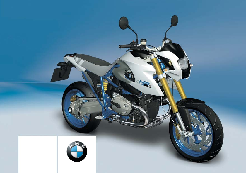
Rider's Manual
HP2 Megamoto
BMW Motorrad
The Ultimate Riding
Machine
Page 2
Motorcycle data/dealership details
Motorcycle data
Model
Vehicle identification number
Colour code
Date of first registration
Registration number
Dealership details
Person to contact in Service department
Ms/Mr
Phone number
Dealership address/phone number (company stamp)
Page 3

Welcome to BMW
We congratulate you on your
choice of a motorcycle from
BMW and welcome you to the
community of BMW riders.
Familiarise yourself with your new
motorcycle so that you can ride it
safely and confidently in all traffic
situations.
Please read this Rider's Manual
carefully before starting to use
your new BMW motorcycle. It
contains important information on
how to operate the controls and
how to make the best possible
use of all your BMW's technical
features.
In addition, it contains information
on maintenance and care to help
you maintain your motorcycle's
reliability and safety, as well as its
value.
If you have questions concerning
your motorcycle, your authorised
BMW Motorrad dealer will gladly
provide advice and assistance.
We hope that you will enjoy riding your BMW and that all your
journeys will be pleasant and
safe.
BMW Motorrad.
Page 4

Table of Contents
You can also consult the index at
the end of this Rider's Manual if
you want to find a particular topic
or item of information.
1 General instructions . .. .. 5
Overview . . . . . . . . . . . . . . . . . . . . . . 6
Abbreviations and symbols . . . . 6
Equipment . . . . . . . . . . . . . . . . . . . . 6
Technical data . . . . . . . . . . . . . . . . 7
Currency . . . . . . . . . . . . . . . . . . . . . . 7
2 General views . .. . .. ... .. . . 9
General view, left side . . . . . . . . 11
General view, right side . . . . . . 13
Underneath the seat . . . . . . . . . 15
Handlebar fitting, left . . . . . . . . . 16
Handlebar fitting, right . . . . . . . . 17
Instrument cluster . . . . . . . . . . . . 18
3 Status indicators .. .. . .. 19
Status indicators . . . . . . . . . . . . . 20
Standard warnings . . . . . . . . . . . 20
ABS warnings
OE
............. 26
4 Operation .. .. .. .. .. .. .. .. 29
Ignition switch and steering
lock . . . . . . . . . . . . . . . . . . . . . . . . . . 30
Electronic immobiliser
(EWS) . . . . . . . . . . . . . . . . . . . . . . . . 31
Clock . . . . . . . . . . . . . . . . . . . . . . . . . 32
Multifunction display . . . . . . . . . 32
Lights . . . . . . . . . . . . . . . . . . . . . . . . 34
Turn indicators . . . . . . . . . . . . . . . 35
Hazard warning flashers . . . . . . 36
Emergency off switch (kill
switch) . . . . . . . . . . . . . . . . . . . . . . . 37
BMW Motorrad ABS
OE
...... 37
Clutch . . . . . . . . . . . . . . . . . . . . . . . . 38
Brakes . . . . . . . . . . . . . . . . . . . . . . . 39
Mirrors . . . . . . . . . . . . . . . . . . . . . . . 40
Handlebars . . . . . . . . . . . . . . . . . . . 40
Spring preload . . . . . . . . . . . . . . . 43
Damping . . . . . . . . . . . . . . . . . . . . . 46
Motorcycle height . . . . . . . . . . . . 49
Tyres . . . . . . . . . . . . . . . . . . . . . . . . . 55
Headlight . . . . . . . . . . . . . . . . . . . . . 55
Seat . . . . . . . . . . . . . . . . . . . . . . . . . . 56
5 Riding . .. .. .. .. .. .. .. .. .. . 59
Safety instructions . . . . . . . . . . . 60
Checklist . . . . . . . . . . . . . . . . . . . . . 62
Starting. . . . . . . . . . . . . . . . . . . . . . . 62
Running in . . . . . . . . . . . . . . . . . . . 64
Brake system . . . . . . . . . . . . . . . . 65
Parking your motorcycle . . . . . 66
Refuelling . . . . . . . . . . . . . . . . . . . . 67
6 Engineering details .. .. . 71
Brake system with BMW Motorrad ABS
OE
................ 72
7 Accessories . .. .. .. .. .. .. 75
General instructions . . . . . . . . . . 76
Power socket . . . . . . . . . . . . . . . . 76
Luggage . . . . . . . . . . . . . . . . . . . . . 77
8 Maintenance . .. .. .. .. .. . 79
General instructions . . . . . . . . . . 80
Toolkit. . . . . . . . . . . . . . . . . . . . . . . . 80
Engine oil . . . . . . . . . . . . . . . . . . . . 80
Brake system . . . . . . . . . . . . . . . . 82
Brake pads . . . . . . . . . . . . . . . . . . . 83
Brake fluid . . . . . . . . . . . . . . . . . . . . 85
Clutch . . . . . . . . . . . . . . . . . . . . . . . . 87
Page 5

Tyres . . . . . . . . . . . . . . . . . . . . . . . . . 88
Rims . . . . . . . . . . . . . . . . . . . . . . . . . 88
Wheels . . . . . . . . . . . . . . . . . . . . . . . 88
Front-wheel stand . . . . . . . . . . . . 94
Rear-wheel stand . . . . . . . . . . . . 95
Bulbs . . . . . . . . . . . . . . . . . . . . . . . . . 96
Jump starting . . . . . . . . . . . . . . 106
Battery . . . . . . . . . . . . . . . . . . . . . 107
Number-plate carrier . . . . . . . 110
9 Care . .. . .. ... .. . .. ... .. . . 113
Care products . . . . . . . . . . . . . . 114
Washing motorcycle . . . . . . . . 114
Cleaning easily damaged
components . . . . . . . . . . . . . . . . 114
Paint care . . . . . . . . . . . . . . . . . . 115
Protective wax coating . . . . . 116
Laying up motorcycle . . . . . . 116
Restoring motorcycle to
use......................... 116
10 Technical data . .. ... . 117
Troubleshooting chart . . . . . . 118
Threaded fasteners . . . . . . . . 119
Engine . . . . . . . . . . . . . . . . . . . . . 122
Fuel . . . . . . . . . . . . . . . . . . . . . . . . 123
Engine oil . . . . . . . . . . . . . . . . . . 123
Clutch . . . . . . . . . . . . . . . . . . . . . . 124
Transmission . . . . . . . . . . . . . . . 125
Rear-wheel drive . . . . . . . . . . . 125
Running gear . . . . . . . . . . . . . . . 126
Brakes . . . . . . . . . . . . . . . . . . . . . 127
Wheels and tyres . . . . . . . . . . . 127
Electrics . . . . . . . . . . . . . . . . . . . . 129
Frame . . . . . . . . . . . . . . . . . . . . . . 130
Dimensions . . . . . . . . . . . . . . . . 131
Weights . . . . . . . . . . . . . . . . . . . . 132
Riding specifications . . . . . . . 132
11 Service . .. .. .. .. .. .. .. . 133
BMW Motorrad service . . . . . 134
BMW Motorrad service
quality . . . . . . . . . . . . . . . . . . . . . . 134
BMW Motorrad Service
Card: on-the-spot break-
down assistance . . . . . . . . . . . 134
BMW Motorrad service net-
work . . . . . . . . . . . . . . . . . . . . . . . . 135
Maintenance work . . . . . . . . . . 135
Confirmation of mainten-
ance work . . . . . . . . . . . . . . . . . . 136
Confirmation of service . . . . . 141
Page 6

Page 7

General instructions
Overview ............................. 6
Abbreviations and symbols ........... 6
Equipment ............................ 6
Technical data ........................ 7
Currency .............................. 7
1
z
5
General instructions
Page 8
Overview
1
Chapter 2 of this Rider's Manual will provide you with an initial
6
overview of your motorcycle. All
maintenance and repair work on
the motorcycle is documented in
Chapter 11. This record of the
maintenance work you have had
performed on your motorcycle is
a precondition for generous treatment of goodwill claims.
When the time comes to sell
your BMW, please remember
to hand over this Rider's Manual; it is an important part of the
motorcycle.
z
General instructions
Abbreviations and symbols
Indicates warnings that you
must comply with for reasons of your safety and the safety
of others, and to protect your
motorcycle against damage.
Specific instructions on
how to operate, control, adjust or look after items of equipment on the motorcycle.
Indicates the end of an
item of information.
Instruction.
Result of an activity.
Reference to a page with
more detailed information.
Indicates the end of a
passage relating to specific accessories or items
of equipment.
Tightening torque.
Item of technical data.
OE Optional extra
The motorcycles are assembled complete with
all the BMW optional extras originally ordered.
OA Optional accessory
You can obtain optional accessories through
your authorised BMW
Motorrad dealer; optional
accessories have to be
retrofitted to the motorcycle.
Electronic immobiliser
EWS
(Elektronische Wegfahrsicherung).
Anti-lock brake system
ABS
Equipment
When you ordered your BMW
motorcycle, you chose various
items of custom equipment. This
Rider's Manual describes option-
Page 9

al extras (OE) offered by BMW
and selected optional accessories (OA). This explains why the
manual may also contain descriptions of equipment which
you have not ordered. Please
note, too, that your motorcycle
might not be exactly as illustrated in this manual on account
of country-specific differences.
If your BMW was supplied with
equipment not described in
this Rider's Manual, you will
find these features described in
separate manuals.
Technical data
All dimensions, weights and
power ratings stated in the
Rider's Manual are quoted to the
standards and comply with the
tolerance requirements of the
Deutsche Institut für Normung e.
V. (DIN). Versions for individual
countries may differ.
Currency
The high safety and quality
standards of BMW motorcycles
are maintained by constant
development work on designs,
equipment and accessories.
Because of this, your motorcycle
may differ from the information
supplied in the Rider's Manual.
Nor can BMW Motorrad entirely
rule out errors and omissions.
We hope you will appreciate that
no claims can be entertained on
the basis of the data, illustrations
or descriptions in this manual.
1
z
7
General instructions
Page 10

1
z
8
General instructions
Page 11

General views
General view, left side ................ 11
General view, right side . . ............ 13
Underneath the seat ................. 15
Handlebar fitting, left ................. 16
Handlebar fitting, right . . . ............ 17
Instrument cluster ................... 18
2
z
9
General views
Page 12
2
10
z
General views
Page 13

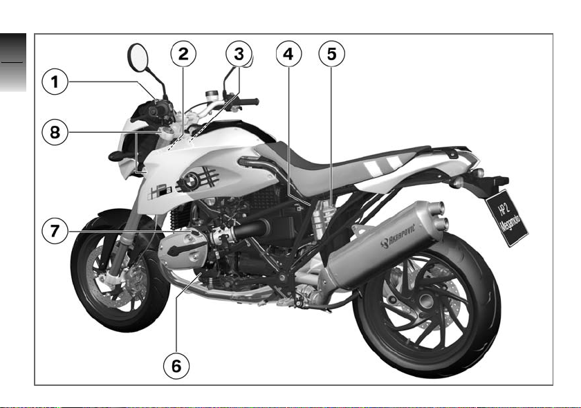
General view, left side
1 Clutch-fluid reservoir
( 87)
2 Fuel-level indicator on fuel
tank ( 67)
3 VIN (on steering head, right)
4 Adjuster for damping
characteristic, rear
suspension (compression
stage) ( 46)
5 Adjuster for spring preload,
rear ( 43)
6 Engine oil level indicator
( 80)
7 Engine-oil filler neck
( 81)
8 Height adjustment of the
telescopic forks ( 49)
2
11
z
General views
Page 14
2
12
z
General views
Page 15

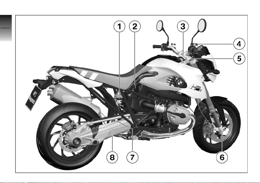
General view, right side
1 Brake-fluid reservoir, rear
( 86)
2 Power socket ( 76)
3 Adjustable handlebars
( 40)
4 Brake-fluid reservoir, front
( 85)
5 Adjuster for damping char-
acteristic, front suspension
(rebound stage) ( 46)
6 Adjuster for damping char-
acteristic, front suspension (compression stage)
( 46)
7 Adjuster for damping char-
acteristic, rear suspension
(rebound stage) ( 46)
8 Setting spring-strut length
( 49)
2
13
z
General views
Page 16
2
14
z
General views
Page 17

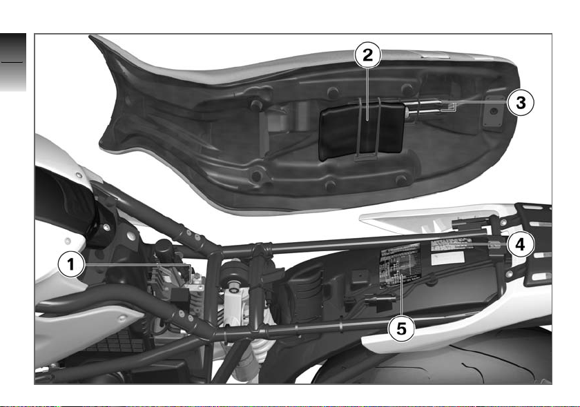
Underneath the seat
1 Battery ( 107)
2 Rider's Manual
3 Toolkit
4 Weights table
5 Table of tyre pressures
2
15
z
General views
Page 18
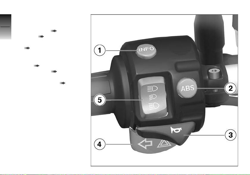
Handlebar fitting, left
2
1 Operating the multifunc-
16
z
tion display ( 32), Setting
clock ( 32)
2 Operating the ABS
( 37)
3 Horn
4 Flashing turn indicators,
left ( 35), Hazard warning flashers ( 36)
5 Headlight flasher and high-
beam headlight ( 34)
General views
OE
Page 19
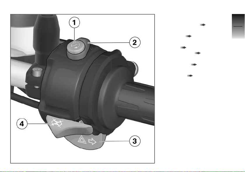
Handlebar fitting, right
1 Starter button ( 62)
2 Emergency off switch (kill
switch) ( 37)
3 Flashing turn indicators,
right ( 36), Hazard warning flashers ( 36)
4 Cancel button, flashing turn
indicators ( 36), Pushbutton, cancel hazard warning
flashers ( 37)
2
17
z
General views
Page 20
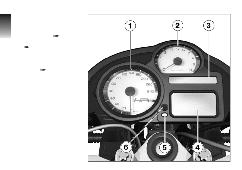
Instrument cluster
2
1 Speedometer
2 Rev. counter
18
3 Telltale lights ( 20)
4 Multifunction display
( 20)
5 Sensor for instrument light-
ing
6 Operating the multifunction
display ( 32)
z
General views
Page 21

Status indicators
Status indicators ..................... 20
Standard warnings ................... 20
ABS warningsOE..................... 26
3
19
z
Status indicators
Page 22
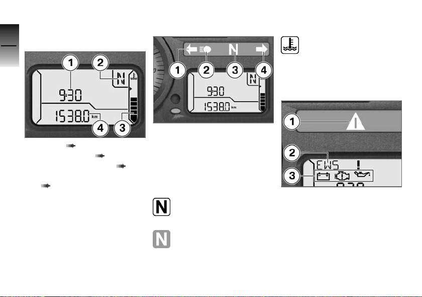
Status indicators
3
Multifunction display
20
1 Clock ( 32)
2 Gear indicator ( 20)
3 Engine temperature ( 20)
4 Odometer and tripmeters
z
Status indicators
( 32)
Telltale lights
1 Flashing turn indicators, left
2 High-beam headlight
3 Idle
4 Flashing turn indicators,
right
Gear indicator
The gear engaged or N
for neutral appears on the
display.
If no gear is engaged, the
'neutral' telltale light also
lights up.
Engine temperature
The horizontal bars below
the temperature symbol
indicate the engine temperature.
Standard warnings
Mode of presentation
Warnings are indicated by the
'General' warning light 1 showing in combination with a warning
word, for example 2 or one of the
warning symbols 3. The 'General' warning light shows red or yellow, depending on the urgency
of the warning. If two or more
warnings occur at the same time,
Page 23

all the appropriate warning symbols appear. Warnings in plaintext form alternate.
The possible warnings are listed
on the next page.
3
21
z
Status indicators
Page 24
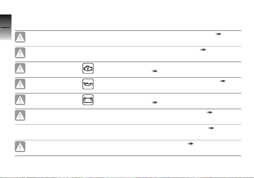
Warnings, overview
3
Telltale lights Status indicators Meaning
22
z
Status indicators
Lights up yellow
Lights up yellow
Lights up yellow Appears on the dis-
Flashes red Appears on the dis-
Lights up red Appears on the dis-
Lights up yellow
EWS ! appears on
the display
FUEL ! appears
on the display
play
play
play
LAMPR ! appears
on the display
LAMPF ! appears
on the display
Lights up yellow
LAMPS ! appears
on the display
Electronic immobiliser active ( 23)
Fuel down to reserve ( 23)
Engine in emergency-operation mode
( 23)
Insufficient engine oil pressure ( 24)
Insufficient battery charge current
( 24)
Rear light bulb defective ( 24)
Front light bulb defective ( 25)
Bulbs defective ( 25)
Page 25
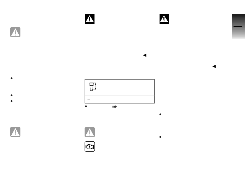
Electronic immobiliser
active
General warning light shows
yellow.
EWS ! appears on the display.
Possible cause:
The key being used is not au-
thorised for starting, or communication between key and engine
electronics is disrupted.
Remove all other vehicle keys
from the same ring as the ignition key.
Use the reserve key.
Have the defective key replaced, preferably by an authorised BMW Motorrad dealer.
Fuel down to reserve
General warning light shows
yellow.
FUEL ! appears on the display.
Lack of fuel can result in
the engine misfiring and
cutting out unexpectedly. Misfiring can damage the catalytic
converter; a hazardous situation
can result if the engine cuts out
unexpectedly.
Do not run the fuel tank dry.
Possible cause:
The fuel tank contains no more
than the reserve quantity of fuel.
Fuel reserve
≥4l
Refuelling ( 68)
Engine in emergencyoperation mode
General warning light shows
yellow.
Engine symbol appears on
the display.
The engine is running in
emergency operating mode.
Engine power might be reduced
and this can cause hazardous
situations, particularly if you attempt to overtake other road
users.
Engine power level might be
lower than normal: adapt your
style of riding accordingly.
Possible cause:
The engine control unit has dia-
gnosed a fault. In exceptional
cases, the engine stops and refuses to start. Otherwise, the engine runs in emergency operating
mode.
You can continue to ride, but
bear in mind that the usual engine power might not be available.
Have the fault rectified as
quickly as possible by a
specialist workshop, preferably
3
23
z
Status indicators
Page 26
an authorised BMW Motorrad
dealer.
3
24
Insufficient engine oil
pressure
General warning light
flashes red.
Oil-can symbol appears on
the display.
The oil pressure in the lube-oil
system is too low. Stop immediately and switch off the engine.
The insufficient oil pres-
z
Status indicators
sure warning does not fulfil
the function of an oil gauge. The
only way of checking whether the
oil level is correct is to check the
oil sight glass.
Possible cause:
The engine-oil level is too low.
Check the engine oil level
( 80)
If the oil level is too low:
Top up the engine oil ( 81)
Possible cause:
The engine-oil pressure is insuffi-
cient.
Riding when engine-oil
pressure is low can result
in engine damage.
Do not continue your journey.
Have the fault rectified as
quickly as possible by a
specialist workshop, preferably
an authorised BMW Motorrad
dealer.
Insufficient battery charge
current
General warning light shows
red.
Battery symbol appears on
the display.
A discharged battery can
render various systems unavailable, for example the lights,
the engine or the ABS. This can
result in dangerous situations.
If possible, do not continue your
journey.
Battery is not being charged. If
you continue to ride the motorcycle the on-board electronics
will drain the battery.
Possible cause:
Alternator or alternator drive belt
defective
Have the fault rectified as
quickly as possible by a
specialist workshop, preferably
an authorised BMW Motorrad
dealer.
Rear light bulb defective
General warning light shows
yellow.
LAMPR ! appears on the dis-
play.
Page 27
A defective bulb places
your safety at risk because
it is easier for other users to
oversee the motorcycle.
Replace defective bulbs as
soon as possible; always carry a
complete set of spare bulbs if
possible.
Possible cause:
Rear light or brake light bulb de-
fective.
Replacing brake light and rear
light bulb ( 100)
Front light bulb defective
LAMPF ! appears on the dis-
play.
A defective bulb places
your safety at risk because
it is easier for other users to
oversee the motorcycle.
Replace defective bulbs as
soon as possible; always carry a
complete set of spare bulbs if
possible.
Possible cause:
Low-beam headlight, high-beam
headlight, side light or turn signal
bulb defective.
Replacing low-beam and highbeam headlight bulb ( 97)
Replacing parking-light bulb
( 98)
Replacing turn indicator bulbs
( 103)
The number-plate carrier can
be removed for sporty riding.
This fault message reminds you
that the motorcycle is temporarily without turn indicators and
number-plate light.
Install the number-plate carrier
( 111)
Bulbs defective
General warning light shows
yellow.
LAMPS ! appears on the dis-
play.
A defective bulb places
your safety at risk because
it is easier for other users to
oversee the motorcycle.
Replace defective bulbs as
soon as possible; always carry a
complete set of spare bulbs if
possible.
Possible cause:
A combination of the bulb de-
fects described above has occurred.
See the fault descriptions
above.
3
25
z
Status indicators
Page 28
ABS warnings
3
Mode of presentation
26
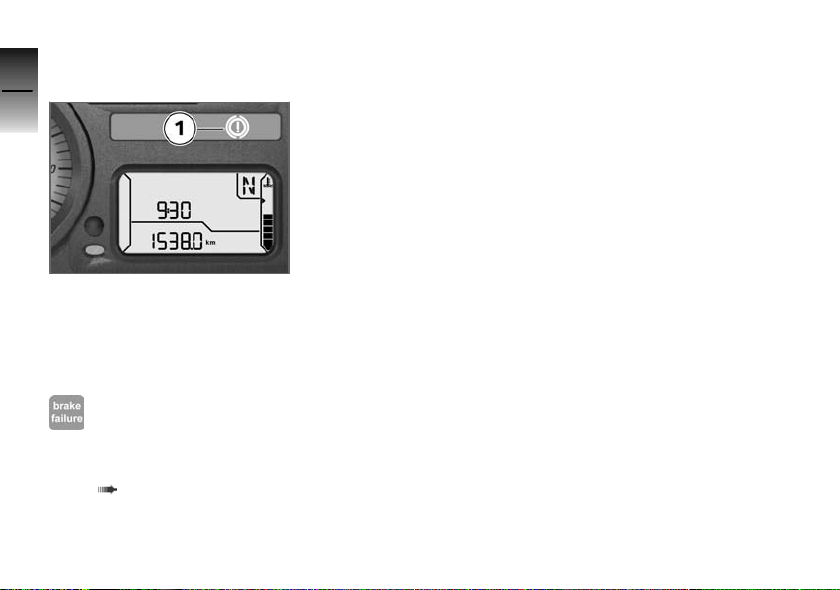
ABS warnings are indicated by
ABS warning light 1.
The way in which the ABS warning light indicates status can dif-
z
Status indicators
fer in some countries.
Possible national variant.
The detailed descriptions relating
to BMW Motorrad ABS start on
page ( 72), and you will find
an overview listing the possible
warnings on the next page.
OE
Page 29
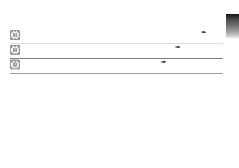
Warnings, overview
Telltale lights Status indicators Meaning
Flashes
Self-diagnosis not completed ( 28)
3
27
Lights up
Lights up
ABS deactivated ( 28)
ABS fault ( 28)
z
Status indicators
Page 30
Self-diagnosis not
3
completed
28
z
Status indicators
ABS warning light flashes.
Possible cause:
The ABS function is not
available, because selfdiagnosis did not complete. The
motorcycle has to move forward
a few metres for the wheel
sensors to be tested.
Pull away slowly. Bear in mind
that the ABS function is not
available until self-diagnosis has
completed.
ABS deactivated
ABS warning light shows.
Possible cause:
The rider has switched off the
ABS system.
with BMW Motorrad ABS
Activate the ABS function
( 38)
OE
ABS fault
ABS warning light shows.
Possible cause:
The ABS control unit has detec-
ted a fault. The ABS function is
not available.
You can continue to ride the
motorcycle, but make due provision for the fact that the ABS
function is not available. Bear
in mind the more detailed information on situations that can
lead to an ABS fault ( 73).
Have the fault rectified as
quickly as possible by a
specialist workshop, preferably
an authorised BMW Motorrad
dealer.
Page 31

Operation
Ignition switch and steering lock ..... 30
Electronic immobiliser (EWS) ........ 31
Clock ................................ 32
Multifunction display ................. 32
Lights ................................ 34
Turn indicators....................... 35
Hazard warning flashers. . ............ 36
Emergency off switch (kill switch) . . . . 37
BMW Motorrad ABS
Clutch ............................... 38
Brakes ............................... 39
Mirrors ............................... 40
Handlebars . . . ....................... 40
Spring preload ....................... 43
Damping ............................. 46
OE
.............. 37
Motorcycle height . .................. 49
Tyres . . . ............................. 55
Headlight ............................ 55
Seat ................................. 56
4
29
z
Operation
Page 32
Ignition switch and
4
steering lock
30
Keys
You receive one master key and
one spare key, plus a key for removing the seat. Please consult
the information on the electronic
immobiliser (EWS) if a key is lost
or mislaid ( 31).
Ignition switch and steering lock
and the cap of the fuel tank are
z
Operation
all operated with the same key.
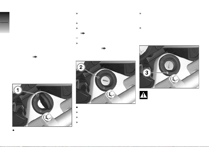
Switching on ignition
Turn the key to position 1.
Side light and all function circuits switched on.
Engine can be started.
Pre-ride check is performed.
( 63)
with BMW Motorrad ABS
ABS self-diagnosis is
performed. ( 63)
Switching off ignition
Turn the key to position 2.
Lights switched off.
Handlebars not locked.
Key can be removed.
Electrically powered accessories remain operational for a limited period of time.
The battery can be recharged
via the on-board socket.
OE
Locking handlebars
If the motorcycle is on the
side stand, the surface of
the ground will determine whether it is better to turn the handlebars to the left or right. However,
the motorcycle is more stable on
a level surface with the handlebars turned to the left than with
the handlebars turned to the
right.
Page 33

On level ground, always turn the
handlebars to the left to set the
steering lock.
Turn the handlebars to the full
left or right lock position.
Turn the key to position 3,
while moving the handlebars
slightly.
Ignition, lights and all function
circuits switched off.
Handlebars locked.
Key can be removed.
Electronic immobiliser (EWS)
Protection against theft
The electronic immobiliser helps
protect your BMW motorcycle
from theft, and this enhanced security is at your disposal without
any need for you to set parameters or activate additional systems.
The engine of a motorcycle fitted with this electronic immobiliser can be started only with the
keys that belong to the vehicle.
You can also have your authorised BMW Motorrad dealer bar
individual keys, for example if a
particular key goes missing. The
engine cannot be started with a
key that has been barred.
In-key electronics
The motorcycle's electronics
exchange certain continuously
changing signals with the electronics in the key; these signals
are specific to your motorcycle
and they are transmitted via the
ring aerial in the ignition lock.
The ignition is not enabled for
starting until the key has been
recognised as "authorised" for
your motorcycle.
A spare key attached to
the same ring as the ignition key used to start the engine could "irritate" the electronics, in which case the enabling
signal for starting is not issued.
The
EWS warning appears in the
multifunction display.
Always keep the spare key separately from the ignition key.
Replacement and extra
keys
You can obtain replacement/extra
keys only through an authorised
BMW Motorrad dealer. The keys
are part of an integrated security system, so the dealer is under an obligation to check the
legitimacy of all applications for
replacement/extra keys. If you
want to have a lost key barred,
you have to bring with you all
the other keys that belong to
the motorcycle. A key that has
been barred can subsequently be
cleared and reactivated for use.
4
31
z
Operation
Page 34
Clock
4
Setting clock
32
z
Operation
Attempting to set the clock
while riding the motorcycle
can lead to accidents.
Set the clock only when the motorcycle is stationary.
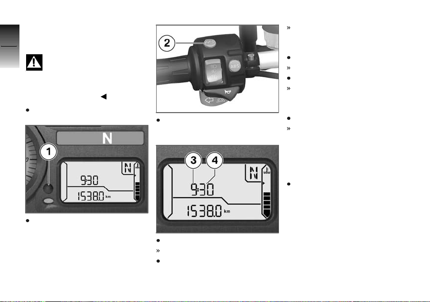
Switch on the ignition.
Repeatedly press button 1 until
the odometer reading appears
on the display.
If you prefer, you can use button 2 for this purpose.
Hold down the button.
Hours reading 3 flashes.
Press the button.
The hours reading increments
by one each time you press
the button.
Hold down the button.
Minutes reading 4 flashes.
Press the button.
The minutes reading increments by one each time you
press the button.
Hold down the button.
The clock is now set and the
time appears on the display.
Multifunction display
Selecting readings
Switch on the ignition.
Page 35
4
33
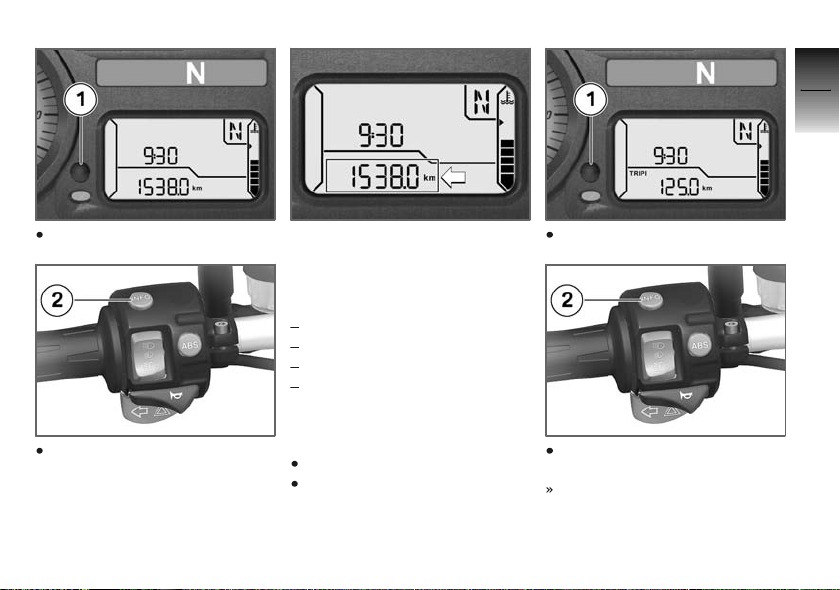
Press button 1.
If you prefer, you can use button 2 for this purpose.
The odometer's display field
starts with the current value and
cycles through the following sequence:
Total distance covered
Tripmeter 1 (Trip I)
Tripmeter 2 (Trip II)
Residual range (once fuel level
is down to reserve)
Resetting tripmeter
Switch on the ignition.
Select the desired tripmeter.
Press and hold down button 1.
If you prefer, you can use button 2 for this purpose.
The tripmeter is reset to zero.
z
Operation
Page 36
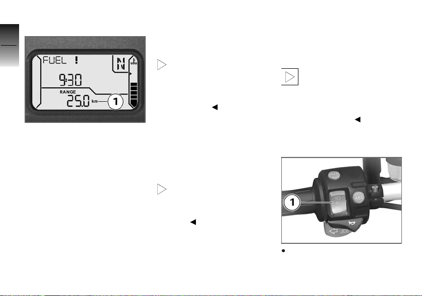
Residual range
4
34
Residual-range reading 1 appears accompanied by the word
z
Operation
RANGE and indicates how far
you can ride with the fuel remaining in the tank. This reading is
not displayed until fuel level has
dropped to reserve. This distance is calculated on the basis
of fuel level and average consumption.
When refuelling after running on
reserve, make sure that you top
up the tank to a level above reserve, as otherwise the sensor
will not be able to register the
new level. If the sensor can-
not register the new level the
residual-range readout cannot be
updated.
The calculated range is an
approximate value. Consequently, BMW Motorrad recommends that you should not
try to use the full residual range
before refuelling.
Lights
Side light
The side lights switch on automatically when the ignition is
switched on.
The side lights place
a strain on the battery.
Do not switch the ignition
on for longer than absolutely
necessary.
Low-beam headlight
The low-beam headlight switches
on automatically when you start
the engine.
When the engine is not
running you can switch on
the lights by switching on the ignition and either switching on the
high-beam headlight or operating
the headlight flasher.
Switching on high-beam
headlight
Press the top section of fullbeam headlight switch 1.
Page 37
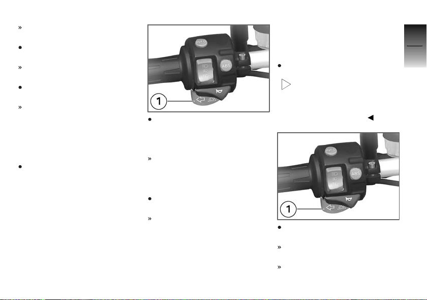
High-beam headlight switched
on.
Move full-beam headlight
switch 1 to the centre position.
High-beam headlight switched
off.
Press the bottom section of
full-beam headlight switch 1.
The high-beam headlight is
switched on until you release
the button (headlight flasher).
Switching on parking
lights
Switch off the ignition.
Immediately after switching
off the ignition, press and hold
down button 1 for the left turn
indicators.
Parking light switches on.
Switching on parking
lights
Switch the ignition on and then
off again.
Parking lights switched off.
Turn indicators
Switching on left flashing
turn indicators
Switch on the ignition.
The turn indicators are can-
celled automatically after
you have ridden for approximately 10 seconds, or covered a
distance of about 200 m.
Press button 1 for the lefthand turn indicators.
Left-hand turn indicators
switched on.
Telltale light for left-hand turn
indicators flashes.
4
35
z
Operation
Page 38
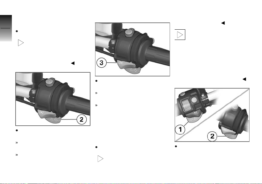
Switching on right
4
flashing turn indicators
Switch on the ignition.
36
The turn indicators are can-
celled automatically after
you have ridden for approximately 10 seconds, or covered a
distance of about 200 m.
z
Operation
Press button 2 for the righthand turn indicators.
Right-hand turn indicators
switched on.
Telltale light for right-hand turn
indicators flashes.
Cancelling turn indicators
Press turn-indicator cancel button 3.
Flashing turn indicators
switched off.
Turn indicator telltale lights off.
Hazard warning flashers
Switching on hazard
warning flashers
Switch on the ignition.
The hazard warning flashers place a strain on the
battery. Do not use the hazard
warning flashers for longer than
absolutely necessary.
If you press a turn-indicat-
or button with the ignition
switched on, the turn-indicator
function is activated instead of
the hazard warning flashers, and
remains active until you release
the button. The hazard warning
flashers recommence flashing as
soon as the button is released.
Simultaneously press button 1
for left turn indicators and button 2 for right turn indicators.
Page 39
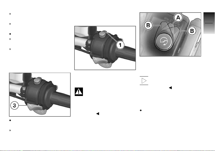
The hazard warning flashers
are switched on.
Left and right turn indicator
telltale lights flash.
Switch off the ignition.
The hazard warning flashers
continue to operate.
Left and right turn indicator
telltale lights are off.
Switching off hazard
warning flashers
Press turn-indicator cancel button 3.
Hazard warning flashers
switched off.
Emergency off switch (kill switch)
1 Emergency off switch (kill
switch)
Operating the kill switch
when riding can cause
the rear wheel to lock and thus
cause a fall.
Do not operate the kill switch
when riding.
The emergency off switch is a
kill switch for switching off the
engine quickly and easily.
A Normal operating position
(run)
B Engine switched off.
You cannot start the engine
unless the kill switch is in
the run position.
BMW Motorrad ABS
OE
Deactivating ABS function
Bring the motorcycle to a stop
or, if the motorcycle is at a
standstill, switch on the ignition.
4
37
z
Operation
Page 40
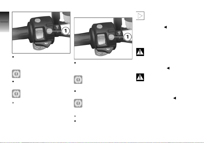
4
38
Press and hold down ABS button 1 until the ABS warning
light changes status.
z
Operation
ABS warning light shows.
Release the ABS button within
two seconds.
ABS warning light remains
ON.
The ABS function is deactivated.
Activating ABS function
Press and hold down ABS button 1 until the ABS warning
light changes status.
ABS warning light goes out;
if self-diagnosis has not
completed it starts flashing.
Release the ABS button within
two seconds.
The ABS warning light remains off or continues to
flash.
The ABS function is activated.
You also have the option of
switching the ignition off and
then on again.
If you switch the ignition off
then on again and the ABS
light comes back on, there is a
fault in the ABS.
Clutch
Adjusting clutch lever
If the position of the clutch
fluid reservoir is changed,
air can enter the clutch system.
Do not twist the handlebar fitting
or the handlebars.
Attempting to adjust the
clutch lever while riding the
motorcycle can lead to accidents.
Do not attempt to adjust the
clutch lever unless the motorcycle is at a standstill.
Page 41
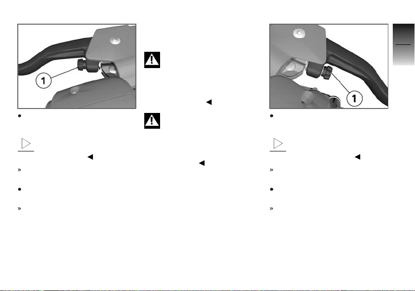
Turn adjusting screw 1 clockwise.
The adjusting screw is easier to turn if you push the
clutch lever forward.
Span between handlebar grip
and clutch lever increases.
Turn adjusting screw 1
counter-clockwise.
Span between handlebar grip
and clutch lever decreases.
Brakes
Adjusting handbrake lever
Changing the position of
the brake-fluid reservoir can
allow air to penetrate the brake
system.
Do not twist the handlebar fitting
or the handlebars.
Attempting to adjust the
brake lever while riding the
motorcycle can lead to accidents.
Do not attempt to adjust the
brake lever unless the motorcycle
is at a standstill.
Turn adjusting screw 1 clockwise.
The adjusting screw is easier to turn if you push the
handbrake lever forward.
Span between handlebar grip
and handbrake lever increases.
Turn adjusting screw 1
counter-clockwise.
Span between handlebar grip
and handlebar lever decreases.
4
39
z
Operation
Page 42
Mirrors
4
Adjusting mirrors
40
z
Operation
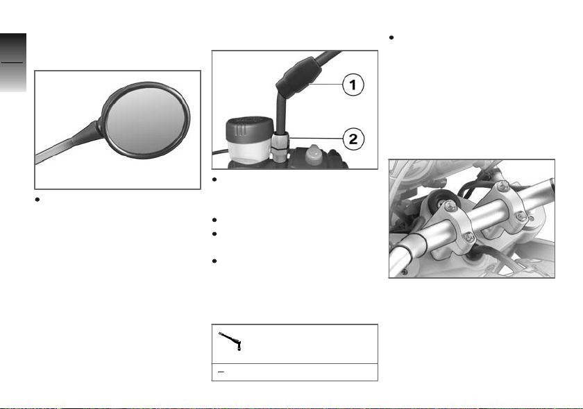
Turn the mirror to the correct
position.
Adjusting mirror arm
Push protective cap 1 up over
the threaded fastener on the
mirror arm.
Slacken nut 2.
Turn the mirror arm to the appropriate position.
Tighten the nut to the specified tightening torque, while
holding the mirror arm to ensure that it does not move out
of position.
Mirror to clamping piece
25 Nm
Push the protective cap over
the threaded fastener.
Handlebars
Adjustable handlebars
You can turn the handlebar
clamping blocks 180° to increase
or decrease handlebar reach.
Short-reach position, handlebars
toward rider.
Page 43
4
41
Long-reach position, handlebars
away from rider.
Adjusting handlebars
Make sure the ground is level
and firm and place the motorcycle on its stand.
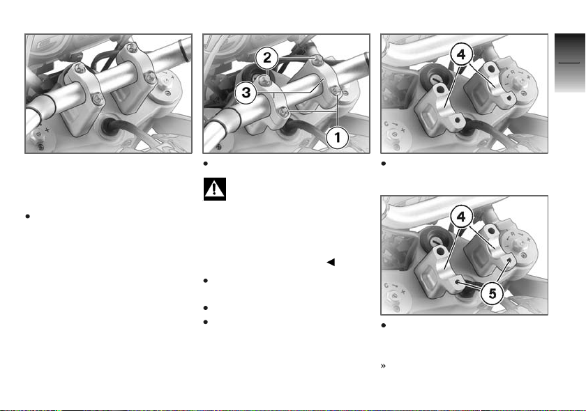
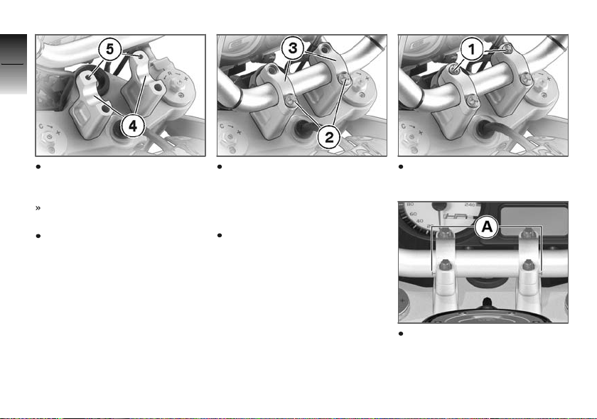
Remove small screws 1.
Tilting the handlebars too
far can allow air to enter the
fluid reservoirs and make its way
into the hydraulic systems.
Hold the handlebars or lay them
down in such a way that the
reservoirs remain upright.
While holding the handlebars,
remove large screws 2.
Remove top clamping blocks 3.
Lift the handlebars clear of the
bottom clamping blocks.
Remove bottom handlebar
clamping blocks 4.
Place bottom handlebar clamping blocks 4 in position with
tapped holes 5 to the rear.
Handlebars toward rider (shorter reach).
z
Operation
Page 44
4
42
Place bottom handlebar clamping blocks 4 in position with
tapped holes 5 to the front.
z
Operation
Handlebars away from rider
(longer reach).
Install the bottom handlebar
clamping blocks in the desired
position for the appropriate
reach.
Position the handlebars and
top handlebar clamping
blocks 3 on the bottom
handlebar clamping blocks, and
hold the handlebars in position.
Install large screws 2, but do
not tighten.
Install small screws 1, but do
not tighten.
Align the handlebars in the
clamping blocks such that the
centres of the marks A are in
line with the gaps between
Page 45
the top and bottom clamping
blocks.
Threaded fasteners not
tightened to the specified
torque can work loose or their
threads can suffer damage.
Always have the security of the
fasteners checked by a specialist
workshop, preferably an authorised BMW Motorrad dealer.
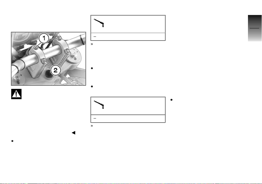
Tighten large screws 2 to the
specified tightening torque.
Handlebar clamping
block to fork bridge
38 Nm
Make sure that there is no gap
between the handlebar clamping blocks on the side where
the large screws are located.
If necessary, slacken screws 1
and retighten screws 2 to the
specified tightening torque.
Tighten small screws 1 to the
specified tightening torque.
Handlebar to handlebar
clamping block
19 Nm
A gap remains between the
handlebar clamping blocks
on the side where the small
screws are located.
Spring preload
Setting
It is essential to set spring preload of the rear suspension to
suit the load carried by the motorcycle. Increase spring preload
when the motorcycle is heavily
loaded and reduce spring preload
accordingly when the motorcycle
is lightly loaded.
Adjusting spring preload
for rear wheel
Make sure the ground is level
and firm and place the motorcycle on its stand.
4
43
z
Operation
Page 46
4
44
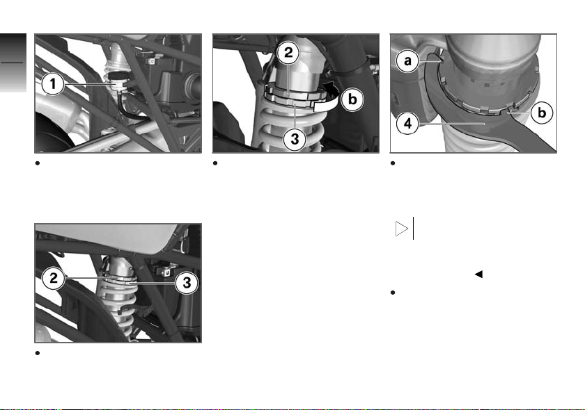
Remove brake-fluid reservoir 1
from the holder, push the hose
down slightly and lay the reser-
z
Operation
voir on the Paralever link.
Use adjusting rings 2 and 3 to
adjust spring preload.
Release the lock by turning
adjusting ring 2 in direction b
with the tool from the toolkit,
while holding adjusting ring 3
with second tool from the
toolkit.
To turn the adjusting rings, engage tools 4 in such a way that
hook a or hook b securely engages a groove.
The adjusting rings can be
turned in either direction
without turning the tool over:
simply engage the appropriate
hook in a groove.
Make sure there is no load
on the motorcycle; remove all
items of luggage, if carried.
Page 47
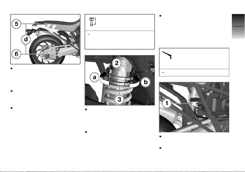
Measure distance d between
the bottom edge of luggageplate recess 5 and the top
edge of axle tube 6.
Apply the weight of the rider
(and passenger, if applicable) to
the motorcycle.
With the assistance of a
second person, measure
distance d between points 5
and 6 again and calculate the
difference between the two
readings.
load-dependent adjustment of spring preload
40 mm (Negative spring displacement of rear wheel under load)
If you want to reduce the difference (increase spring preload, in other words), turn adjusting ring 3 in direction a.
If you want to increase the difference (reduce spring preload,
in other words), turn adjusting
ring 3 in direction b.
Tighten the lock by tightening adjusting ring 2 in direction a with the tool from the
toolkit, while holding adjusting
ring 3 with second tool from
the toolkit.
Locknut of spring basic
setting at top spring re-
tainer
5Nm
Seat brake-fluid reservoir 1 in
the holder.
Adjust the damping characteristic to suit spring preload.
4
45
z
Operation
Page 48
Damping
4
Setting
46
Damping must be adapted to suit
the surface on which the motorcycle is ridden and to suit spring
preload.
An uneven surface requires
softer damping than a smooth
surface.
An increase in spring preload
requires firmer damping, a re-
z
Operation
duction in spring preload requires softer damping.
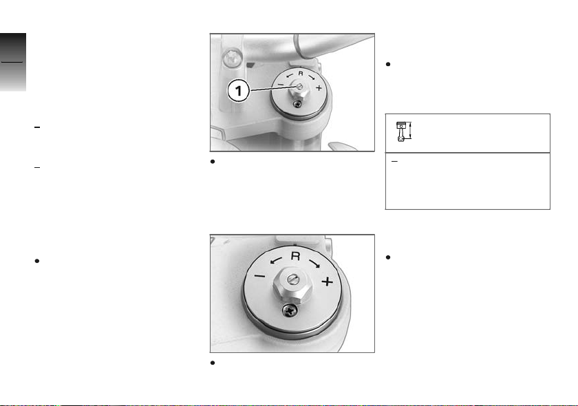
Adjusting front rebound
stage
Make sure the ground is level
and firm and place the motorcycle on its stand.
Use adjusting screws 1 on left
and right to adjust the rebound
stage. Make sure that the settings are identical on left and
right.
If you want to increase damping, use a screwdriver to turn
the adjusting screws on left
and right in the + direction.
If you want to reduce damping,
use a screwdriver to turn the
adjusting screws on left and
right in the - direction.
Rebound stage, basic
setting, front
Turn top adjusting screw
as far as it will go in the "+"
direction, then back it off 10
clicks in the "-" direction.
Adjusting front
compression stage
Make sure the ground is level
and firm and place the motorcycle on its stand.
Page 49
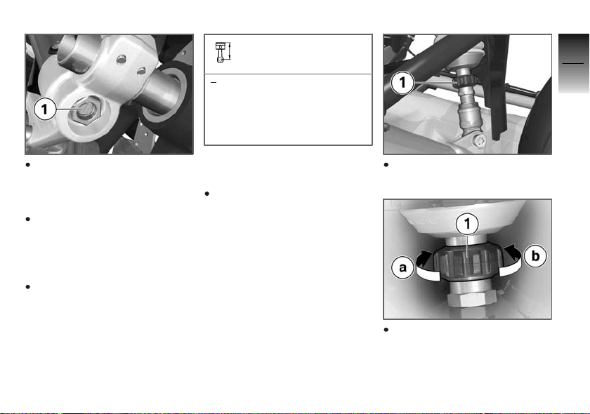
Compression stage, basic
setting, front
Turn bottom adjusting screw
as far as it will go in the
clockwise direction, then
back it off 10 clicks in the
counter-clockwise direction.
4
47
Use adjusting screws 1 on left
and right to adjust the compression stage. Make sure that
the settings are identical.
If you want to increase damping, use a screwdriver to turn
the adjusting screws on left
and right in the clockwise direction.
If you want to reduce damping,
use a screwdriver to turn the
adjusting screws on left and
right in the counter-clockwise
direction.
Adjusting rear rebound
stage
Make sure the ground is level
and firm and place the motorcycle on its stand.
Adjust the rebound stage by
turning adjusting ring 1.
If you want to reduce the rebound stage, turn adjusting
ring 1 in direction a.
z
Operation
Page 50
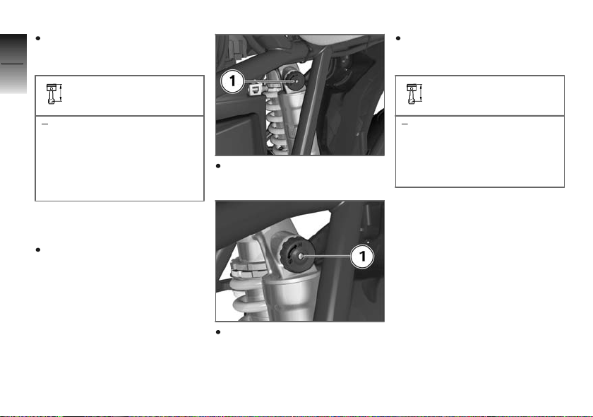
If you want to increase the rebound stage, turn adjusting
4
ring 1 in direction b.
48
Rebound stage, basic
setting, rear
If you want to reduce the compression stage, turn adjusting
ring 1 in the S direction.
Compression stage, basic
setting, rear
Turn adjusting screw as far
as it will go in the counterclockwise direction, as
viewed from above, then turn
it 19 clicks in the clockwise
z
direction.
Operation
Adjusting rear
compression stage
Make sure the ground is level
and firm and place the motorcycle on its stand.
Adjust the compression stage
by turning adjusting ring 1.
If you want to increase the
compression stage, turn adjusting ring 1 in the H direction.
Turn adjusting screw as far
as it will go in the clockwise
direction, then back it off 12
clicks in the counter-clockwise direction.
Page 51

Motorcycle height
Setting
The telescopic forks and the
sprig strut adjust to three different settings, which means that
the height of the motorcycle and
therefore the height of the seat
can be varied. An extra-high seat
is available as an optional accessory.
The position of the fixed fork
tubes in the fork bridges can
be varied.
The length of the sprig strut
can be varied.
When changing the height of the
motorcycle, always be sure to set
the front and rear adjusters to
the same settings.
BMW Motorrad recommends
riding with the adjusters set for
the high position.
4
49
z
Operation
Page 52
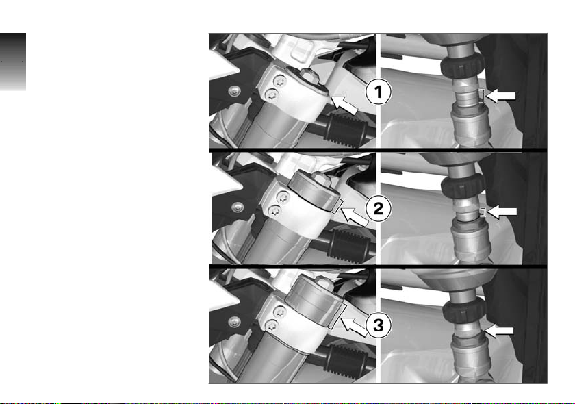
Overview of possible
4
motorcycle heights
1 Setting for telescopic forks
50
z
and spring strut for maximum motorcycle height.
2 Setting for telescopic forks
and spring strut for medium
motorcycle height.
3 Setting for telescopic forks
and spring strut for minimum motorcycle height.
Operation
Page 53
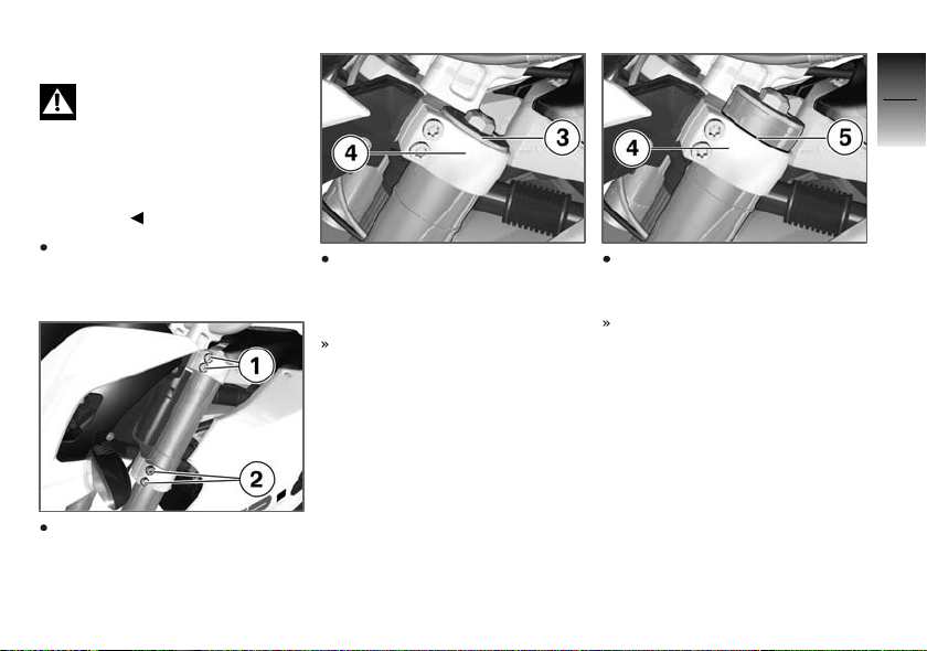
Adjusting fork height
Setting the telescopic forks
and the spring strut to different heights would have a detrimental effect on handling.
Always match the height settings
of the telescopic forks and the
spring strut.
Make sure the ground is level
and firm and place the motorcycle on its stand.
Slacken screws 1 and
screws 2 for the left or right
fixed fork tube.
Align the fixed fork tube so
that the bottom edge of sealing cap 3 is flush with the top
edge of top fork bridge 4.
Setting for maximum motorcycle height.
Align the fixed fork tube so that
ring mark 5 is flush with the
top edge of top fork bridge 4.
Setting for medium motorcycle
height.
4
51
z
Operation
Page 54
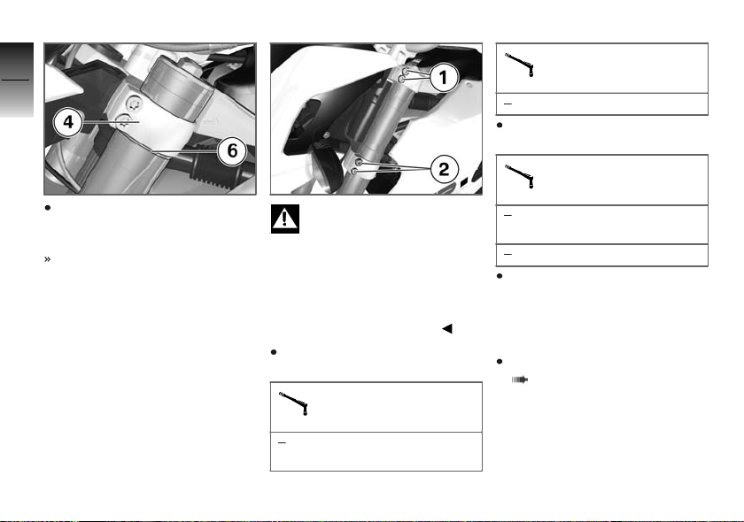
4
52
Push the fixed fork tube into
top fork bridge 4 all the way to
stop 6.
z
Operation
Setting for minimum motorcycle height.
Threaded fasteners not
tightened to the specified
torque can work loose or their
threads can suffer damage.
Always have the security of the
fasteners checked by a specialist
workshop, preferably an authorised BMW Motorrad dealer.
Tighten screws 2 to the specified tightening torque.
Fork bridge, bottom, to
fork fixed tube
Tightening sequence: 2x
each side, alternately
Fork bridge, bottom, to
fork fixed tube
10 Nm
Tighten screws 1 to the specified tightening torque.
Fork bridge, top, to fork
fixed tube
Tightening sequence: 2x
each side, alternately
24 Nm
Repeat the procedure for
the second fixed fork tube.
Make sure that the settings
are identical for both fixed fork
tubes.
Adjust the spring-strut length
( 53)
Page 55
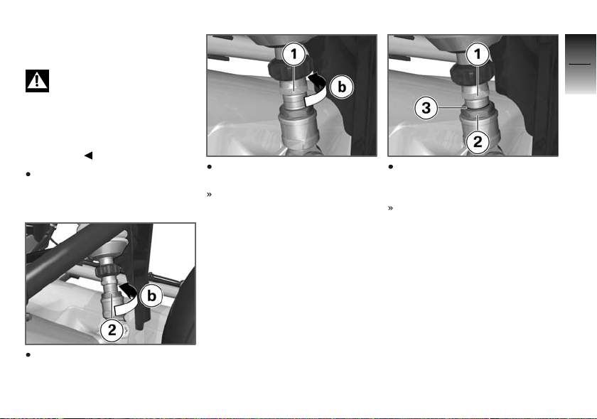
Adjusting spring-strut
length
Setting the telescopic forks
and the spring strut to different heights would have a detrimental effect on handling.
Always match the height settings
of the telescopic forks and the
spring strut.
Make sure the ground is level
and firm and place the motorcycle on its stand.
Slacken nut 2 by turning it in
direction b.
Turn nut 1 all the way in direction b.
Setting for maximum motorcycle height.
Turn nut 1 until ring groove 3
is in line with the top edge of
nut 2.
Setting for medium motorcycle
height.
4
53
z
Operation
Page 56
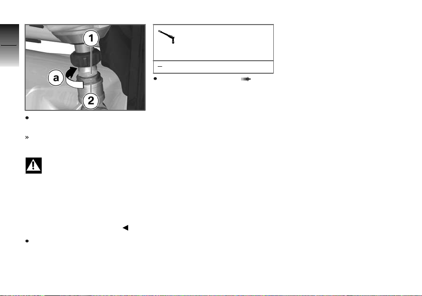
4
54
Turn nut 1 all the way in direction a.
Setting for minimum motor-
z
Operation
cycle height.
Threaded fasteners not
tightened to the specified
torque can work loose or their
threads can suffer damage.
Always have the security of the
fasteners checked by a specialist
workshop, preferably an authorised BMW Motorrad dealer.
Tighten nut 2 in direction a to
lock the adjuster.
Locknut of length adjustment at bottom spring
retainer
40 Nm
Adjust the fork height ( 51)
Page 57
Tyres
Checking tyre pressure
Make sure the ground is level
and firm and place the motorcycle on its stand.
Incorrect tyre pressures im-
pair the motorcycle's handling characteristics and increase
the rate of tyre wear.
Always check that the tyre pressures are correct.
At high road speeds, tyre
valves have a tendency to
open as a result of centrifugal
force.
Fit valve caps with rubber seals
and screw them on firmly to prevent sudden deflation.
Check tyre pressures against
the data below.
Tyre pressure, front
2.2 bar (one-up, tyre cold)
Tyre pressure, front
with rear footrest
2.2 bar (two-up and/or with
luggage, tyre cold)
Tyre pressure, rear
2.5 bar (one-up, tyre cold)
with rear footrest
2.5 bar (two-up and/or with
luggage, tyre cold)
If tyre pressure is too low:
Correct tyre pressure.
OA
OA
Headlight
Adjusting headlight for
driving on left/driving on
right
If the motorcycle is ridden in a
country where the opposite rule
of the road applies, its asymmetric low-beam headlight will tend
to dazzle oncoming traffic.
Have the headlight set accordingly by a specialist workshop,
preferably an authorised BMW
Motorrad dealer.
Headlight beam throw and
spring preload
Headlight beam throw is generally kept constant when spring
preload is adjusted to suit load.
Spring preload adjustment might
not suffice only if the motorcycle
is very heavily loaded. Under
these circumstances, headlight
beam throw has to be adjusted
4
55
z
Operation
Page 58
to suit the weight carried by the
motorcycle.
4
56
Consult a specialist work-
shop, preferably an authorised BMW Motorrad dealer, if you are unsure whether
the headlight basic setting is
correct.
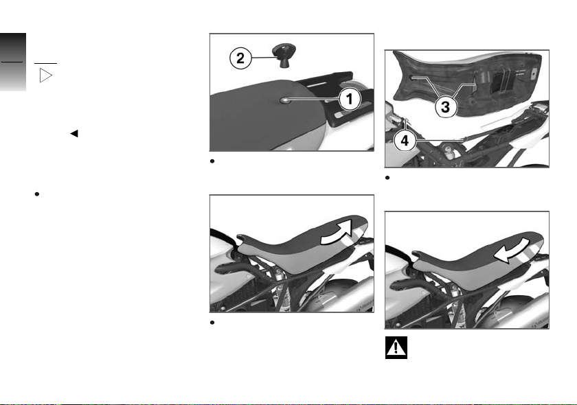
Installing seat
Seat
Removing seat
z
Operation
Make sure the ground is level
and firm and place the motorcycle on its stand.
Remove screw 1 with special
key 2 for the seat.
Pull the seat back and out of
the holders.
Engage seat mounts 3 in holders 4.
If too much pressure is applied in the forward direc-
tion, there is a danger that the
Page 59
motorcycle will be pushed off its
stand.
Always make sure that the
motorcycle is stable and firmly
supported.
Push the seat forward into
holders as far as it will go.
Tighten screw 1 with special
key 2 for the seat until it is
hand-tight.
4
57
z
Operation
Page 60

4
58
z
Operation
Page 61

Riding
Safety instructions ................... 60
Checklist............................. 62
Starting .............................. 62
Running in ........................... 64
Brake system . ....................... 65
Parking your motorcycle . ............ 66
Refuelling ............................ 67
5
59
z
Riding
Page 62
Safety instructions
5
Rider's equipment
60
Do not ride without the correct
clothing. Always wear:
Helmet
Motorcycling jacket and
trousers
Gloves
Boots
z
Riding
This applies even to short journeys, and to every season of the
year. Your authorised BMW Motorrad dealer will be glad to advise you on the correct clothing
for every purpose.
Speed
If you ride at high speed, always
bear in mind that various boundary conditions can adversely affect the handling of your motorcycle:
Settings of the spring-strut and
shock-absorber system
Imbalanced load
Loose clothing
Insufficient tyre pressure
Poor tyre tread
Etc.
Correct loading
Overloading and imbal-
anced loads can adversely
affect the motorcycle's handling.
Do not exceed the permissible
gross weight and be sure to
comply with the instructions on
loading.
Maximum speeds for tyres
The motorcycle's top
speed might be higher than
the maximum speed permitted
for the tyres. Excessive speeds
can damage the tyres and this
could cause accidents.
Comply with the tyre-specific
speed restrictions.
Alcohol and drugs
Even small amounts of
alcohol or drugs will adversely affect your perception
and your ability to assess situations and make decisions, and
slow down your reflexes. Medication can exacerbate these effects.
Do not ride your motorcycle after
consuming alcohol, drugs and/or
medication.
Risk of poisoning
Exhaust fumes contain carbon
monoxide, which is colourless
and odourless but highly toxic.
Inhaling the exhaust fumes
therefore represents a
health hazard and can even
cause loss of consciousness with
fatal consequences.
Do not inhale exhaust fumes.
Page 63
Do not run the engine in an enclosed space.
High voltage
Touching live parts of the
ignition system with the
engine running can cause electric
shock.
Do not touch parts of the ignition system when the engine is
running.
Catalytic converter
If misfiring causes unburned fuel
to enter the catalytic converter,
there is a danger of overheating
and damage.
For this reason, observe the following points:
Do not run the fuel tank dry.
Do not attempt to start or run
the engine with a spark-plug
cap disconnected.
Stop the engine immediately if
it misfires.
Use only unleaded fuel.
Comply with all specified maintenance intervals.
Unburned fuel will destroy
the catalytic converter.
Note the points listed for protection of the catalytic converter.
Risk of fire
Temperatures at the exhaust are
high.
Flammable materials (e.g.
hay, leaves, grass, clothing
and luggage, etc.) could ignite
if allowed to come into contact
with the hot exhaust pipe.
Do not permit flammable materials to come into contact with the
hot exhaust system.
Cooling would be
inadequate if the engine
were allowed to idle for a lengthy
period with the motorcycle at
a standstill: overheating would
result. In extreme cases, the
motorcycle could catch fire.
Do not allow the engine to idle
unnecessarily. Ride away immediately after starting the engine.
Tampering with the
engine control unit
Tampering with the engine
control unit can damage
the motorcycle and cause accidents.
Do not tamper with the engine
control unit.
Tampering with the engine
control unit can result in
mechanical loads that the motorcycle's components are not
designed to withstand. Damage
caused in this way is not covered
by the warranty.
Do not tamper with the engine
control unit.
5
61
z
Riding
Page 64
Checklist
5
Use the following checklist to
check important functions, set-
62
tings and wear limits before you
ride off.
Brakes
Brake-fluid levels, front and rear
Clutch
Clutch fluid level
Damping-characteristic setting
z
Riding
and spring preload
Tyre-tread depth and tyre
pressures
Security of the luggage
At regular intervals:
Engine oil level (every refuelling
stop)
Brake-pad wear (every third
refuelling stop)
Starting
Side stand
You cannot start the motorcycle
with the side stand extended and
a gear engaged. The engine will
switch itself off if you start it with
the gearbox in neutral and then
engage a gear before retracting
the side stand.
Gearbox
You can start the engine when
the gearbox is in neutral or if you
pull the clutch with a gear engaged. Do not pull the clutch until after you have switched on the
ignition, as otherwise the engine
will refuse to start.
Starting engine
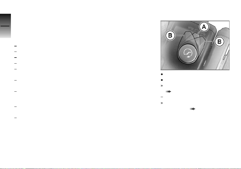
Kill switch in run position A.
Switch on the ignition.
Pre-ride check is performed.
( 63)
with BMW Motorrad ABS
ABS self-diagnosis is
performed. ( 63)
OE
Page 65
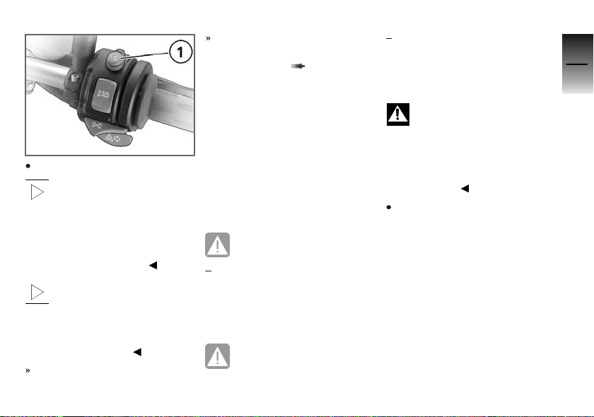
Press starter button 1.
If ambient temperatures are
very low, you might find it
necessary to open the throttle
slightly when starting the engine.
At ambient temperatures below
0 °C, disengage the clutch after
switching on the ignition.
The start attempt is auto-
matically interrupted if battery voltage is too low. Recharge
the battery before you start the
engine, or use jump leads and a
donor battery to start.
The engine starts.
Consult the troubleshooting
chart below if the engine refuses to start. ( 118)
Pre-ride check
The instrument panel runs a test
of the 'General' warning light
when the ignition is switched on:
this is the "Pre-Ride-Check" The
test is aborted if you start the
engine before it completes.
Phase 1
General warning light shows
red.
CHECK! appears on the dis-
play.
Phase 2
General warning light shows
yellow.
CHECK! appears on the dis-
play.
If the 'General' warning light does
not show:
Some malfunctions cannot
be indicated if the 'General' warning light cannot be displayed.
Check that the 'General' warning
light comes on, and that it shows
red and yellow.
Have the fault rectified as
quickly as possible by a
specialist workshop, preferably
an authorised BMW Motorrad
dealer.
ABS self-diagnosis
BMW Motorrad ABS performs
self-diagnosis to ensure its operability. Self-diagnosis is performed automatically when you
switch on the ignition. The motorcycle has to move forward at
OE
5
63
z
Riding
Page 66
a speed above 5 km/h for the
wheel sensors to be tested.
5
Phase 1
64
Test of the diagnosis-compatible system components with
the motorcycle at a standstill.
ABS warning light flashes.
z
Riding
Possible national variant of
the ABS warning light.
Phase 2
Test of the wheel sensors as
the motorcycle pulls away from
rest.
ABS warning light flashes.
Possible national variant of
the ABS warning light.
ABS self-diagnosis
completed
The ABS warning light goes
out.
If an indicator showing an ABS
fault appears when ABS self-diagnosis completes:
You can continue to ride. Bear
in mind that the ABS function
is not yet available.
Have the fault rectified as
quickly as possible by a
specialist workshop, preferably
an authorised BMW Motorrad
dealer.
Running in
The first 1000 km
While running in the motorcycle, vary the throttle opening
and engine-speed range frequently.
Try to do most of your riding during this initial period on
twisting, fairly hilly roads, avoiding high-speed main roads and
highways if possible.
Exceeding the specified en-
gine speeds while running
in will lead to increased engine
wear.
Keep to the specified engine
speeds for running in.
Do not exceed the rpm limits
recommended for running in.
Running-in speed
<4000 min
No full-load acceleration.
Avoid low engine speeds at full
load.
Do not omit the first inspection
after 500 - 1200 km.
-1
Brake pads
New brake pads must "bed
down" and therefore do not
achieve their optimum friction
levels during the first 500 km.
You can compensate for this
initial reduction in braking
Page 67
efficiency by exerting greater
pressure on the levers.
New brake pads can ex-
tend stopping distance by a
significant margin.
Apply the brakes in good time.
Tyres
New tyres have a smooth surface. This must be roughened by
riding in a restrained manner at
various heel angles until the tyres
are run in. This running in procedure is essential if the tyres are
to achieve maximum grip.
Tyres do not have their full
grip when new and there
is a risk of accidents at extreme
angles of heel.
Avoid extreme angles of heel.
Brake system
How can stopping
distance be minimised?
Each time the brakes are applied,
a load distribution shift takes
place with the load shifting forward from the rear to the front
wheel. The sharper the motorcycle decelerates, the more load
is shifted to the front wheel. The
higher the wheel load, the more
braking force can be transmitted
without the wheel locking.
To optimise stopping distance,
apply the front brakes rapidly and
keep on increasing the force you
apply to the brake lever. This
makes the best possible use of
the dynamic increase in load at
the front wheel. Remember to
pull the clutch at the same time.
The rear wheel always has to be
braked as well, in order to make
braking more efficient.
In the "panic braking situations"
that are trained so frequently
braking force is applied as rapidly as possible and with the
rider's full force applied to the
brake levers; under these circumstances the dynamic shift in load
distribution cannot keep pace
with the increase in deceleration
and the tyres cannot transmit the
full braking force to the surface
of the road. Under these circumstances the front wheel can lock
up.
with BMW Motorrad ABS
ABS has to intervene to keep
the front wheel from locking; this
increases stopping distance.
OE
Descending mountain
passes
There is a danger of the
brakes fading if you use
only the rear brakes when descending mountain passes. Under
5
65
z
Riding
Page 68
extreme conditions, the brakes
could overheat and suffer severe
5
damage.
66
Use both front and rear brakes,
and make use of the engine's
braking effect as well.
Wet brakes
After the motorcycle has
z
Riding
been washed, ridden
through water or ridden in
the rain, the brake discs and
pads might be wet and the
brakes might not take effect
immediately.
Apply the brakes in good time
until the brakes have dried out.
Salt on brakes
The brakes may fail to take
effect immediately if the
motorcycle was ridden on saltcovered roads and the brakes
were not applied for some time.
Apply the brakes in good time
until the salt layer on the brake
discs and brake pads has been
removed.
Oil or grease on brakes
Oil and grease on the brake
discs and pads considerably
diminish braking efficiency.
Especially after repair and maintenance work, make sure that the
brake discs and brake pads are
free of oil and grease.
Dirt or mud on brakes
When riding on loose sur-
faces or muddy roads, the
brakes may fail to take effect
immediately because of dirt or
moisture on the discs or brake
pads.
Apply the brakes in good time
until the brakes have been
cleaned.
The brake pads will wear
more rapidly if you ride fre-
quently on unsurfaced tracks or
poor roads.
Check the thickness of the brake
pads more frequently and replace
the brake pads in good time.
Parking your motorcycle
Placing motorcycle on
side stand
If the ground is soft or un-
even, there is no guarantee that the motorcycle will rest
firmly on the stand.
Always check that the ground
under the stand is level and
firm.
Switch off the engine.
Pull the handbrake lever.
Hold the motorcycle upright
and balanced.
Use your left foot to extend the
side stand fully.
Page 69
The side stand is designed
to support only the weight
of the motorcycle.
Do not lean or sit on the
motorcycle with the side stand
extended.
Slowly lean the motorcycle to
the side until its weight is taken
by the stand and dismount to
the left.
If the motorcycle is on the
side stand, the surface of
the ground will determine whether it is better to turn the handlebars to the left or right. However,
the motorcycle is more stable on
a level surface with the handlebars turned to the left than with
the handlebars turned to the
right.
On level ground, always turn the
handlebars to the left to set the
steering lock.
Turn the handlebars to full left
or right lock.
Check that the motorcycle is
standing firmly.
On a gradient, the motorcycle should always face
uphill; select 1st gear.
Lock the steering lock.
Removing motorcycle
from side stand
Unlock the steering lock.
From the left, grip the handlebars with both hands.
Pull the handbrake lever.
Swing your right leg over the
seat and lift the motorcycle to
the upright position.
Hold the motorcycle upright
and balanced.
An extended side stand can
catch on the ground when
the motorcycle is moving and
lead to a fall.
Retract the side stand before
moving the motorcycle.
Sit on the motorcycle and use
your left foot to retract the side
stand.
Refuelling
Fuel level
The fuel tank is made of semitransparent material, so the level
of fuel in the tank is visible. If
you look back from the direction of the telescopic forks, you
can quickly check how much
fuel is in the tank. The 5-litre
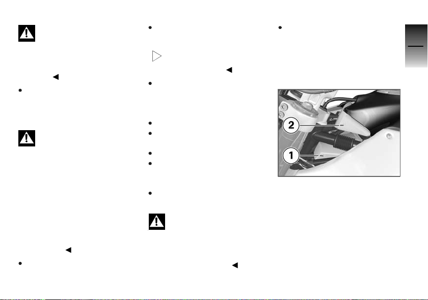
level 1 and the 11-litre level 2
are marked on the fuel tank.
5
67
z
Riding
Page 70
Refuelling
5
68
z
Riding
Fuel is highly flammable. A
naked flame close to the
fuel tank can cause a fire or explosion.
Do not smoke. Never bring a
naked flame near the fuel tank.
Fuel expands when hot.
Fuel escaping from an
overfilled tank could make its way
onto the rear tyre. This could
cause a fall.
Do not fill the tank past the bottom edge of the filler neck.
Fuel attacks plastics, which
become dull or unsightly.
Wipe off plastic parts immediately
if they come into contact with
fuel.
Leaded fuel will destroy the
catalytic converter.
Use only unleaded fuel.
Make sure the ground is level
and firm and place the motorcycle on its stand.
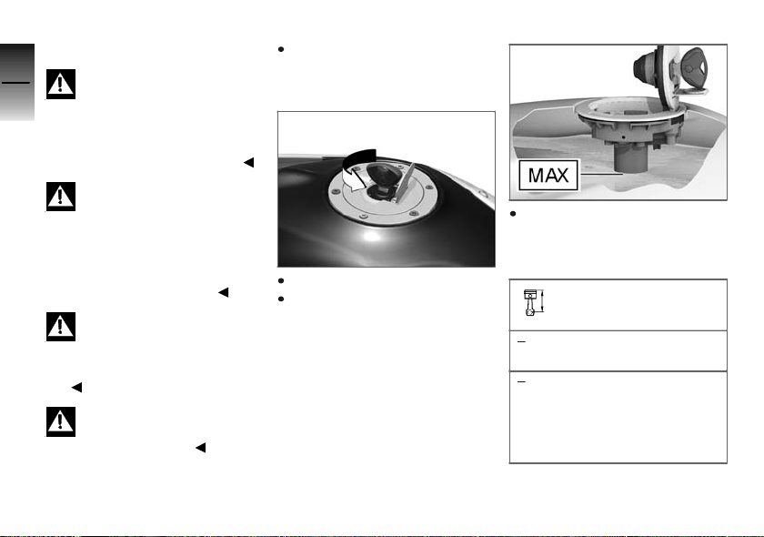
Open the protective cap.
Open the fuel tank cap with
the ignition key by turning it
counter-clockwise.
Refuel with fuel of the grade
stated below; do not fill the
tank past the bottom edge of
the filler neck.
Recommended fuel
grade
98 ROZ/RON (Super plus
(premium))
95 ROZ/RON (Premium
unleaded (fuel grade,
usable with power- and
consumption-related
restrictions))
Page 71
Usable fuel capacity
approx. 13 l
Press the fuel tank cap down
firmly to close.
Remove the key and close the
protective cap.
5
69
z
Riding
Page 72

5
70
z
Riding
Page 73

Engineering details
Brake system with BMW Motorrad
ABSOE.............................. 72
6
71
z
Engineering details
Page 74

Brake system with
6
BMW Motorrad ABS
72
How does ABS work?
The amount of braking force that
can be transferred to the road
depends on factors hat include
the coefficient of friction of the
road surface. Loose stones, ice
and snow or a wet road all have
much lower coefficients of friction than a clean, dry asphalt surface. The lower the coefficient
of friction, the longer the braking
distance.
If the rider increases braking
pressure to the extent that brak-
z
Engineering details
ing force exceeds the maximum transferrable limit, the wheels
start to lock and the motorcycle
loses its directional stability; a fall
is imminent. Before this situation
can occur, ABS intervenes and
adapts braking pressure to the
maximum transferrable braking
force, so the wheels continue
to turn and directional stability
is maintained irrespective of the
OE
condition of the road surface.
What are the effects of
surface irregularities?
Humps and surface irregularities can cause the wheels to lose
contact temporarily with the road
surface; if this happens the braking force that can be transmitted to the road can drop to zero.
If the brakes are applied under
these circumstances the ABS
has to reduce braking force to
ensure that directional stability
is maintained when the wheels
regain contact with the road surface. At this instant the BMW
Motorrad ABS must assume an
extremely low coefficient of friction, so that the wheels will continue to rotate under all imaginable circumstances, because this
is the precondition for ensuring
directional stability. As soon as
is registers the actual circumstances, the system reacts instantly and adjusts braking force
accordingly to achieve optimum
braking.
Rear wheel lift
Under very severe and sudden
deceleration, however, under
certain circumstances it is possible that the BMW Motorrad
ABS will be unable to prevent
the rear wheel from lifting clear
of the ground. If this happens
the outcome can be a highsiding
situation in which the motorcycle
can flip over.
Severe braking can cause
the rear wheel to lift off the
ground.
When you brake, bear in mind
that ABS control cannot be relied
on in all circumstances to prevent
the rear wheel from lifting clear of
the ground.
Page 75

What is the design
baseline for BMW
Motorrad ABS?
Within the limits imposed by
physics, BMW Motorrad ABS ensures directional stability on any
surface. The system is not optimised for special requirements
that apply under extreme competitive situations off-road or on
the track.
Special situations
The speeds of the front and rear
wheels are compared as one
means of detecting a wheel's
incipient tendency to lock. If the
system registers implausible values for a lengthy period the ABS
function is deactivated for safety
reasons and an ABS fault message is issued. Self-diagnosis has to complete before fault
messages can be issued.
In addition to problems with the
BMW Motorrad ABS, exceptional
riding conditions can lead to a
fault message being issued.
Exceptional riding
conditions:
Heating up with the motorcycle
on the centre stand or an auxiliary stand, engine idling or with
a gear engaged.
Rear wheel locked by the engine brake for a lengthy period,
for example while descending
on a loose or slippery surface.
If a fault message is issued on
account of exceptional riding
conditions as outlined above, you
can reactivate the ABS function
by switching the ignition off and
on again.
What significance
devolves on regular
maintenance?
Invariably, a technical sys-
tem cannot perform beyond
the abilities dictated by its level
of maintenance.
In order to ensure that the BMW
Motorrad ABS is always maintained in optimum condition, it
is essential for you to comply
strictly with the specified inspection intervals.
Reserves for safety
The potentially shorter braking
distances which BMW Motorrad
ABS permits must not be used
as an excuse for careless riding.
ABS is primarily a means of ensuring a safety margin in genuine
emergencies.
Take care when cornering. When
you apply the brakes on a corner,
the motorcycle's weight and
6
73
z
Engineering details
Page 76

momentum take over and even
BMW Motorrad ABS is unable to
6
counteract their effects.
74
z
Engineering details
Page 77

Accessories
General instructions.................. 76
Power socket . ....................... 76
Luggage ............................. 77
7
75
z
Accessories
Page 78
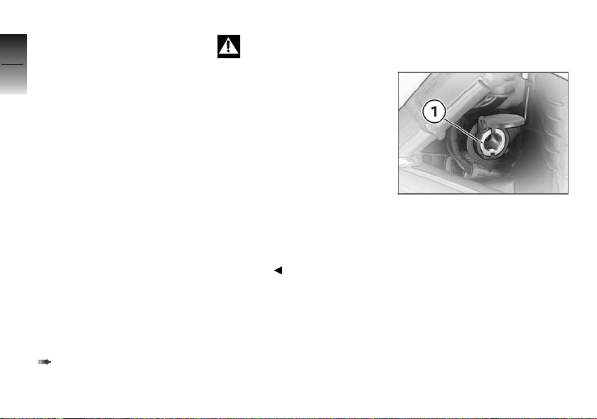
General instructions
7
BMW Motorrad recommends
the use of parts and accessories
76
for your motorcycle that are approved by BMW for this purpose.
Genuine BMW parts and accessories and other products
which BMW has approved can
be obtained from your authorised
BMW Motorrad dealer, together
with expert advice on their installation and use.
These parts and products have
z
Accessories
been tested by BMW for safety,
function and suitability. BMW
accepts product liability for them.
Conversely, BMW is unable to
accept any liability whatsoever
for parts and accessories which it
has not approved.
Also bear in mind the information on the effect of wheel size
on suspension-control systems
( 88).
BMW Motorrad cannot
assess each non-BMW
product to determine whether it can be used on or in connection with BMW motorcycles
without constituting a safety hazard. Country-specific official authorisation does not suffice as
assurance. Tests conducted by
these instances cannot make
provision for all operating conditions experienced by BMW motorcycles and, consequently, they
are not sufficient in some circumstances.
Use only parts and accessories approved by BMW for your
motorcycle.
Whenever you are planning
modifications, comply with all
the legal requirements. Make
sure that the motorcycle does
not infringe national road-vehicle
construction and use regulations.
Power socket
Ratings
The supply to socket 1 is cut off
automatically if battery voltage
is low or the load exceeds the
maximum rating.
Operating electrical
accessories
You can start using electrical accessories only when the ignition
is switched on. The accessory
remains operational if the ignition
is subsequently switched off. In
order to ensure that the drain on
the on-board power supply sys-
Page 79
tem is minimised, the supply to
the power socket is cut off approximately 15 minutes after the
ignition is switched off, and it is
also temporarily interrupted during the start procedure.
Cable routing
The cables from the power socket to the auxiliary device must be
routed in such a way that they:
do not impede the rider
do not restrict or obstruct the
steering angle and handling
characteristics
cannot be trapped
Incorrectly routed cables
can impede the rider.
Route the cables as described
above.
Luggage
Correct loading
Overloading and imbal-
anced loads can adversely
affect the motorcycle's handling.
Do not exceed the permissible
gross weight and be sure to
comply with the instructions on
loading.
Set spring preload, damping
characteristic and tyre pressures to suit total weight.
Note the maximum permissible
payload of the tank rucksack.
Payload of tank rucksack
with tank rucksack
≤5kg
Note the maximum permissible
payload of the rear-light protector.
OA
Payload of cover for rear
light
max 1 kg
7
77
z
Accessories
Page 80

7
78
z
Accessories
Page 81

Maintenance
General instructions.................. 80
Toolkit ............................... 80
Engine oil ............................ 80
Brake system . ....................... 82
Brake pads . . . ....................... 83
Brake fluid ........................... 85
Clutch ............................... 87
Tyres ................................ 88
Rims ................................. 88
Wheels .............................. 88
Front-wheel stand ................... 94
Rear-wheel stand .................... 95
Bulbs ................................ 96
Jump starting . ..................... 106
Battery ............................. 107
Number-plate carrier ............... 110
8
79
z
Maintenance
Page 82
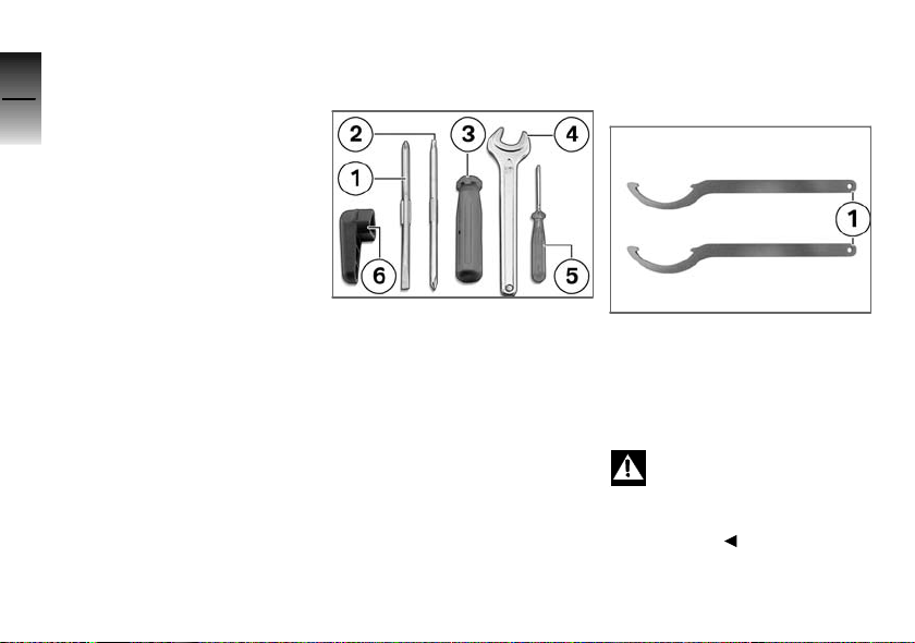
General instructions
8
The Maintenance chapter describes straightforward proced-
80
ures for checking and replacing
certain wear parts.
Special tightening torques are listed as applicable. The tightening
torques for the threaded fasteners on your motorcycle are listed
in the section entitled "Technical
data".
You will find information on more
extensive maintenance and repair
z
Maintenance
work in the Repair Manual on the
CD or DVD that accompanies
your motorcycle.
Toolkit
Overview
1 Reversible screwdriver blade
With star-head and plain-tip
ends
2 Reversible screwdriver blade
With star-head and Torx
T25
3 Screwdriver handle
4 Open-ended spanner
Width across flats 17
5 Small screwdriver with plain
tip
6 Tool for oil cap
For opening the oil filler cap
Onboard toolkit, adjusting
spring strut
1 Hook wrench
For adjusting spring preload
Engine oil
Checking engine oil level
The engine can seize if the
oil level is low, and this can
lead to accidents.
Always make sure that the oil
level is correct.
Page 83
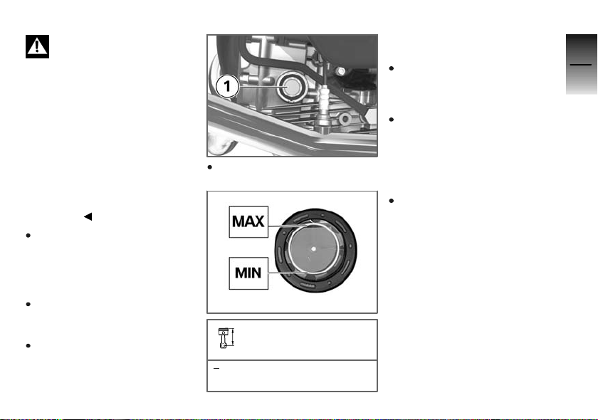
The oil level varies with the
temperature of the oil. The
higher the temperature, the higher the level of oil in the sump.
Checking the oil level with the
engine cold or after no more than
a short ride will lead to misinterpretation; this in turn, means that
the engine will be operated with
the incorrect quantity of oil.
In order to ensure that the engine oil level is read correctly,
check the oil level only after a
lengthy trip.
Check that the engine is at operating temperature, make sure
that the ground is level and
firm and place the motorcycle
on its stand.
Wait five minutes after switching off the engine at operating
temperature.
Hold the motorcycle upright.
Check the oil level in oil-level
indicator 1.
Engine oil level
max 0.5 l (Difference
between MIN and MAX)
If the oil level is below the MIN
mark:
Top up the engine oil.
If the oil level is above the MAX
mark:
Have the oil level corrected by
a specialist workshop, preferably an authorised BMW Motorraddealer.
Topping up engine oil
Make sure the ground is level
and firm and place the motorcycle on its stand.
8
81
z
Maintenance
Page 84
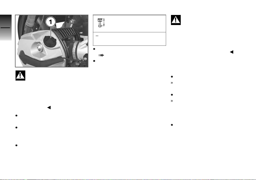
8
82
Damage to the engine
can result if it is operated
without enough oil, but the same
also applies if the oil level is too
z
Maintenance
high.
Always make sure that the oil
level is correct.
Wipe the area around the filler
neck clean.
Use the tool from the toolkit to
remove cap 1 from the engine
oil filler neck.
Top up the engine oil to the
specified level.
Engine oil, quantity for
topping up
max 0.5 l (Difference
between MIN and MAX)
Check the engine oil level
( 80)
Use the tool from the toolkit to
install the cap of the engine-oil
filler neck.
Brake system
Dependability of the brake
system
A fully functional brake system is
a basic requirement for the road
safety of your motorcycle.
Do not ride the motorcycle if you
have any doubts about the dependability of the brake system.
Under these circumstances have
the brake system checked by a
specialist workshop, preferably
an authorised BMW Motorrad
dealer.
Incorrect working practices
endanger the reliability of
the brakes.
Have all work on the brake system performed by a specialist
workshop, preferably an authorised BMW Motorrad dealer.
Checking operation of the
brakes
Pull the handbrake lever.
The pressure point must be
clearly perceptible.
Press the footbrake lever.
The pressure point must be
clearly perceptible.
If pressure points are not clearly
perceptible:
Have the brakes checked by a
specialist workshop, preferably
an authorised BMW Motorrad
dealer.
Page 85
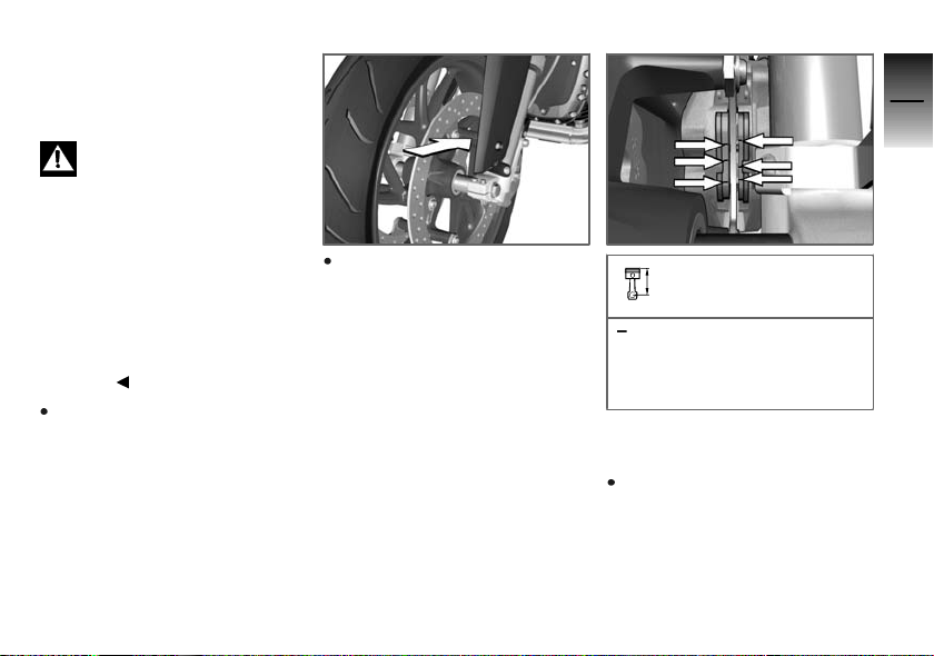
Brake pads
Checking front brake pad
thickness
Brake pads worn past the
minimum permissible thickness can cause a reduction in
braking efficiency and under
certain circumstances they can
cause damage to the brake system.
In order to ensure the dependability of the brake system, do not
permit the brake pads to wear
past the minimum permissible
thickness.
Make sure the ground is level
and firm and place the motorcycle on its stand.
Visually inspect the left and
right brake pads to ascertain
their thickness. Viewing direction: Between wheel and slider
tube toward the brake caliper.
Brake-pad wear limit,
front
min 1 mm (Friction pad only,
without backing plate.The
wear indicators (grooves)
must be clearly visible.)
If the wear indicating marks are
no longer clearly visible:
Have the brake pads replaced
by a specialist workshop,
preferably an authorised BMW
Motorrad dealer.
8
83
z
Maintenance
Page 86
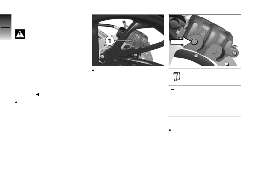
Checking rear brake pad
8
thickness
84
z
Maintenance
Brake pads worn past the
minimum permissible thickness can cause a reduction in
braking efficiency and under
certain circumstances they can
cause damage to the brake system.
In order to ensure the dependability of the brake system, do not
permit the brake pads to wear
past the minimum permissible
thickness.
Make sure the ground is level
and firm and place the motorcycle on its stand.
Visually inspect the brake pads
of rear brake caliper 1 from the
left to ascertain their thickness.
Brake-pad wear limit, rear
1 mm (Friction pad only,
without backing plate. Make
sure that the brake disc is
not visible through the bore
in the inboard brake block.)
If the brake disc is visible:
Have the brake pads replaced
by a specialist workshop,
preferably an authorised BMW
Motorrad dealer.
Page 87
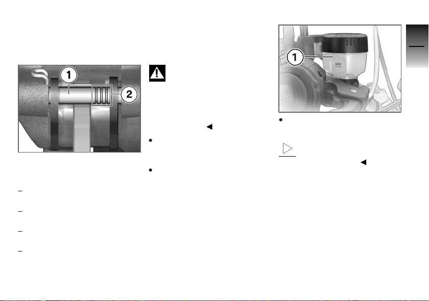
Brake-pad wear
The rear brake has a brake-pad
wear indicator.
Shaft 1 with three marker rings 2
is between the brake pads.
How to interpret the marks:
Three rings visible: brake-pad
thickness is at least 75 %
Two rings visible: brake-pad
thickness is at least 50 %
One ring visible: brake-pad
thickness is at least 25 %
No rings visible: brake pads
worn to wear limit; check as
described above
Brake fluid
Checking brake-fluid
level, front brakes
A low fluid level in the
brake reservoir can allow air
to penetrate the brake system.
This significantly reduces braking
efficiency.
Check the brake-fluid level at
regular intervals.
Make sure the ground is level
and firm and place the motorcycle on its stand.
Move the handlebars to the
straight-ahead position.
Check the brake fluid level in
reservoir 1.
Wear of the brake pads
causes the brake fluid level
in the reservoir to sink.
8
85
z
Maintenance
Page 88
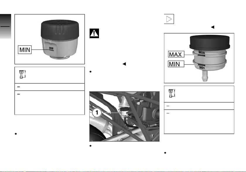
8
86
Brake fluid level, front
z
DOT4 brake fluid
Maintenance
It is impermissible for the
brake fluid level to drop below the MIN mark. (Brakefluid reservoir horizontal)
If the brake fluid level drops below the permitted level:
Have the defect rectified as
quickly as possible by a specialist workshop, preferably
an authorised BMW Motorrad
dealer.
Checking brake-fluid
level, rear brakes
A low fluid level in the
brake reservoir can allow air
to penetrate the brake system.
This significantly reduces braking
efficiency.
Check the brake-fluid level at
regular intervals.
Make sure the ground is level
and firm and hold the motorcycle upright.
Check the brake fluid level in
reservoir 1.
Wear of the brake pads
causes the brake fluid level
in the reservoir to sink.
Brake fluid level, rear
DOT4 brake fluid
It is impermissible for the
brake fluid level to drop below the MIN mark. (Brakefluid reservoir horizontal)
If the brake fluid level drops below the permitted level:
Have the defect rectified as
quickly as possible by a spe-
Page 89
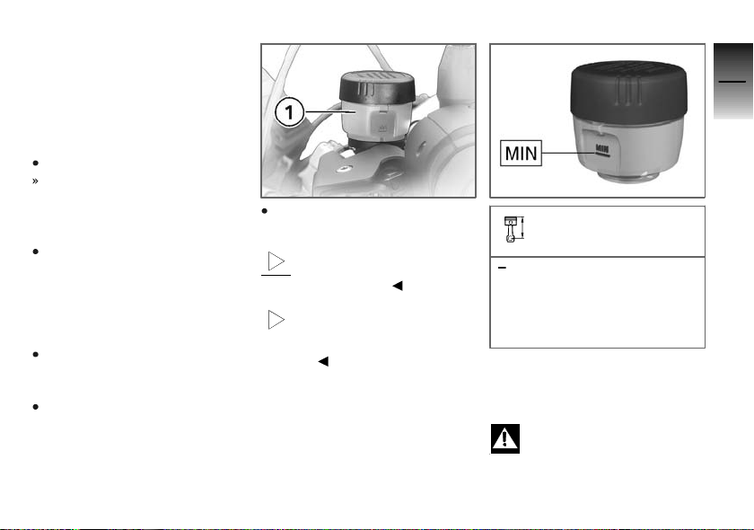
cialist workshop, preferably
an authorised BMW Motorrad
dealer.
Clutch
Checking clutch operation
Pull the clutch lever.
The pressure point must be
clearly perceptible.
If the pressure point is not clearly
perceptible:
Have the clutch checked by a
specialist workshop, preferably
an authorised BMW Motorrad
dealer.
Checking clutch fluid level
Make sure the ground is level
and firm and place the motor-
cycle on its stand.
Move the handlebars to the
straight-ahead position.
Check the clutch fluid level in
reservoir 1.
Wear of the clutch causes
the fluid level in the clutch
fluid reservoir to rise.
The clutch system is filled
with a special hydraulic
fluid that does not have to be
changed.
Clutch-fluid level (visual
inspection)
It is impermissible for the
clutch fluid level to drop.
(Motorcycle upright and
handlebars in straight-ahead
position.)
A drop in clutch-fluid level is indicative of a leak in the clutch
system. If the fluid level drops:
Unsuitable hydraulic fluids
could cause damage to the
clutch system.
8
87
z
Maintenance
Page 90

Do not attempt to top up the
system with fluids of any kind.
8
Have the defect rectified as
88
quickly as possible by a specialist workshop, preferably
an authorised BMW Motorrad
dealer.
Tyres
Measuring tread depth of
tyres
Measure the tyre tread depth
in the main tread grooves with
z
Maintenance
wear marks.
Tyres have wear indicators
integrated into the main
tread grooves. The tyre is worn
out when the tyre tread has worn
down to the level of the marks.
The locations of the marks are
indicated on the edge of the tyre,
e.g. by the letters TI, TWI or by
an arrow.
If the tyre tread no longer complies with the minimum legally
required tread depth:
Replace tyre.
Rims
Visual inspection
Make sure the ground is level
and firm and place the motorcycle on its stand.
Visually inspect the rims for
defects.
Have damaged rims checked
and, if necessary, replaced by a
specialist workshop, preferably
an authorised BMW Motorrad
dealer.
Wheels
Tyre recommendation
For each size of tyre BMW Motorrad tests and classifies as
roadworthy certain makes. BMW
Motorrad cannot assess the suit-
ability or provide any guarantee
of road safety for other tyres.
BMW Motorrad recommends
using only tyres tested by BMW
Motorrad.
You can obtain detailed information from your authorised BMW
Motorrad dealer or on the Internet at www.bmw-motorrad.com.
Effect of wheel size
on suspension-control
systems
Wheel size is very important as a
parameter for the ABS. In particular, the diameter and the width
of a motorcycle's wheels are programmed into the control unit
and are fundamental to all calculations. Any change in these
influencing variables, caused for
example by a switch to wheels
other than those installed exworks, can have serious effects
on the performance of the control systems.
Page 91
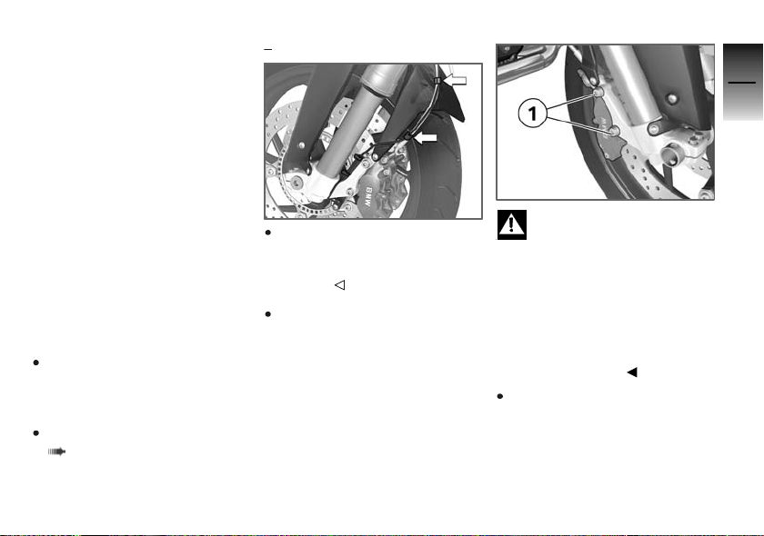
The sensor rings are essential
for correct road-speed calculation, and they too must match
the motorcycle's ABS system
and consequently cannot be
changed.
If you decide that you would like
to fit non-standard wheels to
your motorcycle, it is very important to consult a specialist workshop beforehand, preferably an
authorised BMW Motorrad dealer. In some cases, the data programmed into the control units
can be changed to suit the new
wheel sizes.
Remove the front wheel
Place the motorcycle on an
auxiliary stand; BMW Motorrad
recommends the BMW Motorrad rear-wheel stand.
Install the rear-wheel stand
( 95)
with BMW Motorrad ABS
Unclip the retaining clips holding the ABS sensor cable to
the brake line. Do not open the
cable tie.
Mask off the parts of the wheel
rim that could be scratched in
the process of removing the
brake calipers.
OE
Once the calipers have
been removed, there is
a risk of the brake pads being
pressed together to the extent
that they cannot be slipped back
over the brake disc on reassembly.
Do not operate the handbrake
lever when the brake calipers
have been removed.
Remove securing screws 1 of
the brake calipers on left and
right.
8
89
z
Maintenance
Page 92
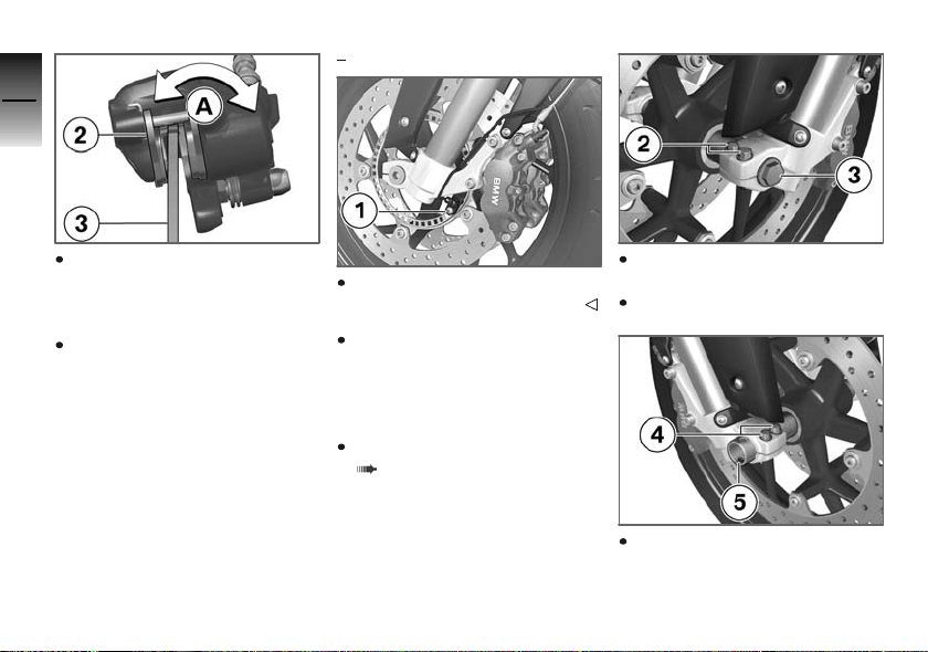
8
90
with BMW Motorrad ABS
OE
Force the brake pads slightly
apart by rocking brake
calipers 2 back and forth A
against brake discs 3.
z
Maintenance
Carefully pull the brake calipers
back and out until clear of the
brake discs.
Remove screw 1 and remove
the ABS sensor from its bore.
Raise front of motorcycle until
the front wheel can turn freely.
BMW Motorrad recommends
the BMW Motorrad front-wheel
stand for lifting the motorcycle.
Install the front-wheel stand
( 94)
Slacken left axle clamping
screws 2.
Remove axle screw 3.
Slacken right axle clamping
screws 4.
Page 93
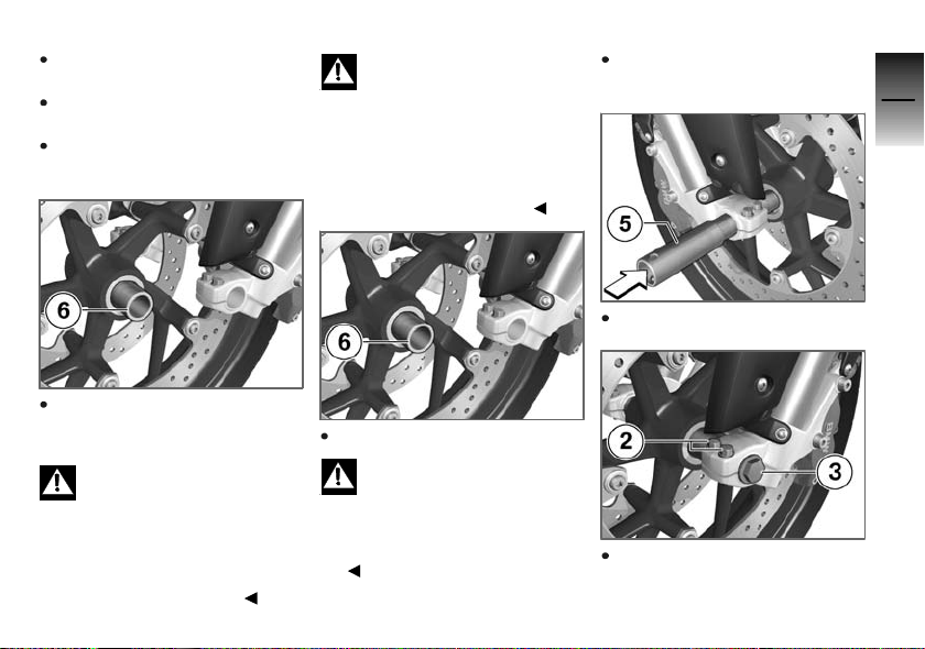
Use a screwdriver to remove
axle 5.
Do not remove the grease from
the axle.
Roll the front wheel clear of the
forks.
Threaded fasteners not
tightened to the specified
torque can work loose or their
threads can suffer damage.
Always have the security of the
fasteners checked by a specialist
workshop, preferably an authorised BMW Motorrad dealer.
Roll the front wheel into position between the forks.
8
91
Remove spacing sleeve 6.
Installing front wheel
Possible malfunctions when
the ABS system intervenes
if non-standard wheels are installed.
See the information on the effect
of wheel size on the ABS system
at the start of this chapter.
Install spacing sleeve 6.
The front wheel must be
installed right way round to
rotate in the correct direction.
Note the direction-of-rotation arrows on the tyre or the wheel
rim.
Insert axle 5.
Tighten axle screw 3 to the
specified torque; if necessary
z
Maintenance
Page 94
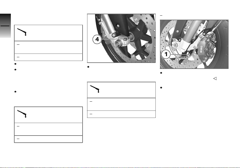
use a screwdriver to counterhold at the other side.
8
92
z
Maintenance
Axle screw of front wheel
in axle holder
Thread-locking compound:
Optimoly TA
50 Nm
Remove the front-wheel stand.
Without operating the brakes:
firmly compress the forks and
release; repeat the procedure
several times.
Tighten left axle clamping
screws 2 to the specified
tightening torque.
Pinch bolt of axle holder
Tightening sequence: 2x
each side, alternately
8Nm
Tighten right axle clamping
screws 4 to the specified tightening torque.
Pinch bolt of axle holder
Tightening sequence: 2x
each side, alternately
8Nm
with BMW Motorrad ABS
Insert the ABS sensor into its
bore and install screw 1.
Ease the brake calipers on to
the brake discs.
OE
Page 95
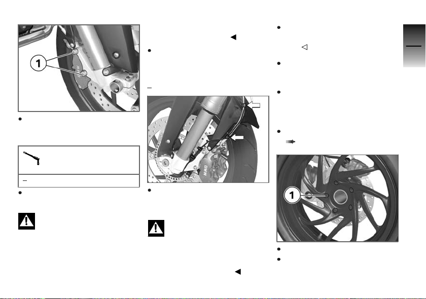
Install securing screws 1 on
left and right and tighten to
specified tightening torque.
Brake caliper to slider
tube
the brake lever is pulled or the
brake pedal depressed.
Operate the brake several
times until the brake pads are
bedded.
with BMW Motorrad ABS
OE
Make sure that the ABS sensor
cable is routed as shown
here.
Remove the rear-wheel stand
Removing rear wheel
Place the motorcycle on an
auxiliary stand; BMW Motorrad
recommends the BMW Motorrad rear-wheel stand.
Install the rear-wheel stand
( 95)
8
93
z
Maintenance
30 Nm
Remove the adhesive tape
from the wheel rim.
Braking efficiency is im-
paired if the brake pads are
not correctly bedded against the
discs.
Before riding off, always check
that the brakes bite as soon as
Close the retaining clips holding the ABS sensor cable to
the brake line.
The cable of the ABS
sensor could chafe through
if it comes into contact with the
brake disc.
Make sure that the ABS sensor
cable is routed correctly.
Remove 5 screws 1.
Remove the rear wheel.
Page 96
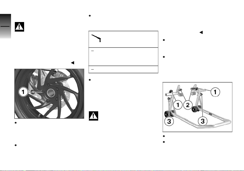
Install the rear wheel
8
94
z
Maintenance
Threaded fasteners not
tightened to the specified
torque can work loose or their
threads can suffer damage.
Always have the security of the
fasteners checked by a specialist
workshop, preferably an authorised BMW Motorrad dealer.
Check that the wheel centering
spigot and contact surfaces
of the wheel hub are free of
grease.
Seat the rear wheel on the
wheel centering spigot.
Hand-tighten 5 wheel studs 1
and then tighten to specified
torque.
Rear wheel to wheel carrier
Tightening sequence: Tighten in diagonally opposite sequence
60 Nm
Remove the rear-wheel stand
Front-wheel stand
Installing front-wheel
stand
The BMW Motorrad front
wheel stand is not designed
to support motorcycles not fitted
with a centre stand or without
other auxiliary stands. A motorcycle resting only on the front
wheel stand and the rear wheel
can topple.
Place the motorcycle on its
centre stand or another auxiliary
stand before lifting the front
wheel with the BMW Motorrad
front-wheel stand.
Make sure the ground is level
and firm and place the motorcycle on its stand.
Use basic stand with tool number (0 402 241) in combination with front-wheel adapter
(0 402 242).
Slacken adjusting screws 1.
Push the two adapters 2 apart
until the front forks fit between
them.
Page 97
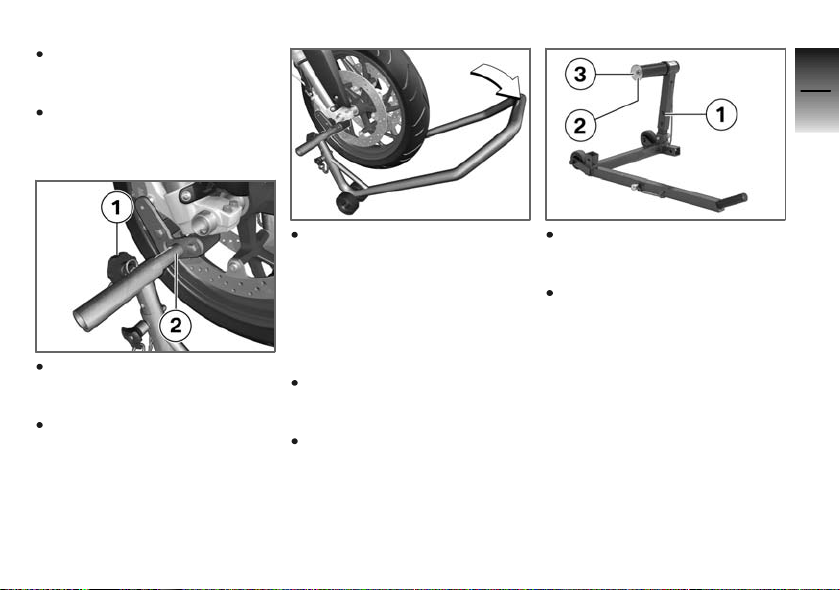
Use locating pins 3 to set the
front-wheel stand to the desired height.
Centre the front-wheel stand
relative to the front wheel and
push it against the front axle.
8
95
Align the two adapters 2 so
that the front forks are securely
seated.
Tighten adjusting screws 1.
Apply uniform pressure to push
the front-wheel stand down
and raise the motorcycle.
Rear-wheel stand
Installing rear-wheel
stand
Make sure the ground is level
and firm and place the motorcycle on its stand.
Use rear-wheel stand with tool
number (0 402 244) with adapter shaft (0 402 250) appropriate to the motorcycle.
Use screws 1 to set the rearwheel stand to the desired
height.
Remove retaining disc 2.To
do so, press release button 3.
z
Maintenance
Page 98
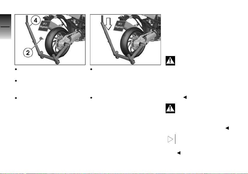
8
96
Push the rear-wheel stand from
the right onto the rear axle.
Push on retaining disc 2 from
the left, while holding the un-
z
Maintenance
lock button down.
Take a grip on the motorcycle
with your left hand, and place
your right hand on lever 4 of
the rear-wheel stand.
Lift the motorcycle upright,
simultaneously pressing the
lever down until the stand supports the motorcycle in the upright position.
Press the lever down to the
ground.
Bulbs
General instructions
A warning appears in the multifunction display if a bulb is defective. If the brake or rear light
fails, the symbol is accompanied by the 'General' warning light,
which lights up yellow. If the rear
light fails the second filament of
the brake light shines at reduced
brightness to double as a rear
light. Even though you have this
substitute rear light, the indicators in the display tell you that a
bulb defect has occurred.
A defective bulb places
your safety at risk because
it is easier for other users to
oversee the motorcycle.
Replace defective bulbs as
soon as possible; always carry a
complete set of spare bulbs if
possible.
The bulb is pressurised and
can cause injury if damaged.
Wear protective goggles and
gloves when changing bulbs.
The types of bulb fitted to
your motorcycle are listed
in the section entitled "Technical
data".
Page 99
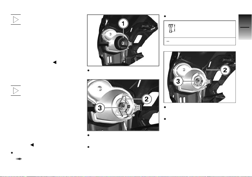
Do not touch the glass of
new bulbs with your fingers.
Use a clean, dry cloth to hold
the bulbs when handling them.
Dirt deposits, in particular oil and
grease, interfere with heat radiation from the bulb. This leads
to overheating and shortens the
bulb's operating life.
Replacing low-beam and
high-beam headlight bulb
The headlight bulbs are
accessible from below,
through the headlight surround.
There is very little space inside
the housing, so to facilitate
identification of the bulbs and
to avoid handling problems,
the procedure for changing
bulbs described below includes
removal of the headlight
surround.
Removing headlight surround
( 98)
Remove rubber cap 1.
Disengage spring clip 2 from
the fastening and swing it up.
Pull high-beam/low-beam
bulb 3 out of the headlight
housing.
Replace the defective bulb.
Bulb for low-beam and
high-beam headlight
H4/12V/60W/55W
Insert bulb 3 into the headlight
housing.
Close and lock spring clips 2.
8
97
z
Maintenance
Page 100
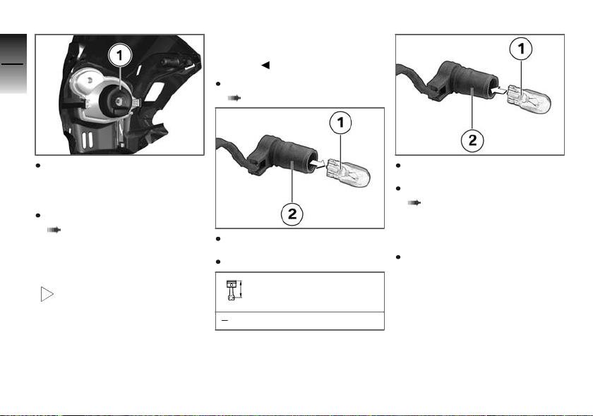
8
98
bulbs described below includes
removal of the headlight
surround.
Removing headlight surround
( 98)
Position the rubber cap 1 on
the headlight housing and push
it into place.
Installing headlight surround
z
Maintenance
( 99)
Replacing parking-light
bulb
The headlight bulbs are
accessible from below,
through the headlight surround.
There is very little space inside
the housing, so to facilitate
identification of the bulbs and
to avoid handling problems,
the procedure for changing
Pull bulb 1 out of socket 2.
Replace the defective bulb.
Bulb for parking light
W5W / 12 V / 5 W
Push bulb 1 into socket 2.
Installing headlight surround
( 99)
Removing headlight
surround
Make sure the ground is level
and firm and place the motorcycle on its stand.
 Loading...