


9200 Series
Multi-Range DC Power Supply
Models: 9201, 9202, 9205, 9206
USER MANUAL
i

Safety Summary
The following safety precautions apply to both operating and maintenance personnel and must be followed during all phases of operation, service, and repair of this instrument.
Before applying power to this instrument:
Read and understand the safety and operational information in this manual.
Apply all the listed safety precautions.
Verify that the voltage selector at the line power cord input is set to the correct line voltage. Operating the instrument at an incorrect line voltage will void the warranty.
Make all connections to the instrument before applying power.
Do not operate the instrument in ways not specified by this manual or by B&K Precision.
Failure to comply with these precautions or with warnings elsewhere in this manual violates the safety standards of design, manufacture, and intended use of the instrument. B&K Precision assumes no liability for a customer’s failure to comply with these requirements.
Category rating
The IEC 61010 standard defines safety category ratings that specify the amount of electrical energy available and the voltage impulses that may occur on electrical conductors associated with these category ratings. The category rating is a Roman numeral of I, II, III, or IV. This rating is also accompanied by a maximum voltage of the circuit to be tested, which defines the voltage impulses expected and required insulation clearances. These categories are:
Category I (CAT I): Measurement instruments whose measurement inputs are not intended to be connected to the mains supply. The voltages in the environment are typically derived from a limited-energy transformer or a battery.
Category II (CAT II): Measurement instruments whose measurement inputs are meant to be connected to the mains supply at a standard wall outlet or similar sources. Example measurement environments are portable tools and household appliances.
Category III (CAT III): Measurement instruments whose measurement inputs are meant to be connected to the mains installation of a building. Examples are measurements inside a building's circuit breaker panel or the wiring of permanently-installed motors.
Category IV (CAT IV): Measurement instruments whose measurement inputs are meant to be connected to the primary power entering a building or other outdoor wiring.
Do not use this instrument in an electrical environment with a higher category rating than what is specified in this manual for this instrument.
ii

You must ensure that each accessory you use with this instrument has a category rating equal to or higher than the instrument's category rating to maintain the instrument's category rating. Failure to do so will lower the category rating of the measuring system.
Electrical Power
This instrument is intended to be powered from a CATEGORY II mains power environment. The mains power should be 120 V RMS or 240 V RMS. Use only the power cord supplied with the instrument and ensure it is appropriate for your country of use.
Ground the Instrument
To minimize shock hazard, the instrument chassis and cabinet must be connected to an electrical safety ground. This instrument is grounded through the ground conductor of the supplied, three-conductor AC line power cable. The power cable must be plugged into an approved three-conductor electrical outlet. The power jack and mating plug of the power cable meet IEC safety standards.
Do not alter or defeat the ground connection. Without the safety ground connection, all accessible conductive parts (including control knobs) may provide an electric shock. Failure to use a properly-grounded approved outlet and the recommended three-conductor AC line power cable may result in injury or death.
Unless otherwise stated, a ground connection on the instrument's front or rear panel is for a reference of potential only and is not to be used as a safety ground.
Do not operate in an explosive or flammable atmosphere
Do not operate the instrument in the presence of flammable gases or vapors, fumes, or finelydivided particulates.
The instrument is designed to be used in office-type indoor environments. Do not operate the instrument
In the presence of noxious, corrosive, or flammable fumes, gases, vapors, chemicals, or finely-divided particulates.
In relative humidity conditions outside the instrument's specifications.
In environments where there is a danger of any liquid being spilled on the instrument or where any liquid can condense on the instrument.
iii

In air temperatures exceeding the specified operating temperatures.
In atmospheric pressures outside the specified altitude limits or where the surrounding gas is not air.
In environments with restricted cooling air flow, even if the air temperatures are within specifications.
In direct sunlight.
This instrument is intended to be used in an indoor pollution degree 2 environment. The operating temperature range is 0 °C to 40 °C and the operating humidity range is up to 80% relative humidity with no condensation allowed.
Measurements made by this instrument may be outside specifications if the instrument is used in non-office-type environments. Such environments may include rapid temperature or humidity changes, sunlight, vibration and/or mechanical shocks, acoustic noise, electrical noise, strong electric fields, or strong magnetic fields.
Do not operate instrument if damaged
 If the instrument is damaged, appears to be damaged, or if any liquid, chemical, or other material gets on or inside the instrument, remove the instrument's power cord, remove the instrument from service, label it as not to be operated, and return the instrument to B&K Precision for repair. Notify B&K Precision of the nature of any contamination of the instrument.
Clean the instrument only as instructed
Do not clean the instrument, its switches, or its terminals with contact cleaners, abrasives, lubricants, solvents, acids/bases, or other such chemicals. Clean the instrument only with a clean dry lint-free cloth or as instructed in this manual.
Not for critical applications
This instrument is not authorized for use in contact with the human body or for use as a component in a life-support device or system.
Do not touch live circuits
Instrument covers must not be removed by operating personnel. Component replacement and internal adjustments must be made by qualified service-trained maintenance personnel who are aware of the hazards involved when the instrument's covers and shields are removed.
iv

Under certain conditions, even with the power cord removed, dangerous voltages may exist when the covers are removed. To avoid injuries, always disconnect the power cord from the instrument, disconnect all other connections (for example, test leads, computer interface cables, etc.), discharge all circuits, and verify there are no hazardous voltages present on any conductors by measurements with a properly-operating voltage-sensing device before touching any internal parts. Verify the voltage-sensing device is working properly before and after making the measurements by testing with known-operating voltage sources and test for both DC and AC voltages. Do not attempt any service or adjustment unless another person capable of rendering first aid and resuscitation is present.
Do not insert any object into an instrument's ventilation openings or other openings.
Hazardous voltages may be present in unexpected locations in circuitry being tested when a fault condition in the circuit exists.
Fuse replacement
Fuse replacement must be done by qualified service-trained maintenance personnel who are aware of the instrument's fuse requirements and safe replacement procedures. Disconnect the instrument from the power line before replacing fuses. Replace fuses only with new fuses of the fuse types, voltage ratings, and current ratings specified in this manual or on the back of the instrument. Failure to do so may damage the instrument, lead to a safety hazard, or cause a fire. Failure to use the specified fuses will void the warranty.
Servicing
Do not substitute parts that are not approved by B&K Precision or modify this instrument. Return the instrument to B&K Precision for service and repair to ensure that safety and performance features are maintained.
Cooling fans
This instrument contains one or more cooling fans. For continued safe operation of the instrument, the air inlet and exhaust openings for these fans must not be blocked nor must accumulated dust or other debris be allowed to reduce air flow. Maintain at least 25 mm clearance around the sides of the instrument that contain air inlet and exhaust ports. If mounted in a rack, position power devices in the rack above the instrument to minimize instrument heating while rack mounted. Do not continue to operate the instrument if you cannot verify the fan is operating (note some fans may have intermittent duty cycles). Do not insert any object into the fan's inlet or outlet.
v

Use correctly sized wires
To connect a load to the power supply, use a wire diameter large enough to handle the maximum continuous output short-circuit current of the power supply without the wire overheating.
For continued safe use of the instrument
Do not place heavy objects on the instrument.
Do not obstruct cooling air flow to the instrument.
Do not place a hot soldering iron on the instrument.
Do not pull the instrument with the power cord, connected probe, or connected test lead.
Do not move the instrument when a probe is connected to a circuit being tested.
vi

Compliance Statements
Disposal of Old Electrical & Electronic Equipment (Applicable in the European Union and other European countries with separate collection systems)
This product is subject to Directive 2002/96/EC of the European Parliament and the Council of the European Union on waste electrical and electronic equipment (WEEE), and in jurisdictions adopting that Directive, is marked as being put on the market after August 13, 2005, and should not be disposed of as unsorted municipal waste. Please utilize your local WEEE collection facilities in the disposition of this product and otherwise observe all applicable requirements.
vii
CE Declaration of Conformity
This instrument meets the requirements of 2006/95/EC Low Voltage Directive and 2004/108/EC Electromagnetic Compatibility Directive with the following standards.
Low Voltage Directive
-EN61010-1: 2001
EMC Directive
-EN 61000-3-2: 2006
-EN 61000-3-3: 1995+A1: 2001+A2: 2005
-EN 61000-4-2 / -3 / -4 / -5 / -6 / -11
-EN 61326-1: 2006
viii

Safety Symbols
Refer to the user manual for warning information to avoid hazard or personal injury and prevent damage to instrument.
Electric Shock hazard
On (Supply). This is the AC mains connect/disconnect switch on the front of the instrument.
Off (Supply). This is the AC mains connect/disconnect switch on the front of the instrument.
Direct current
Alternating current
Fuse Symbol
Chassis (earth ground) symbol
Ground terminal
Protective earth ground
CAUTION indicates a hazardous situation which, if not avoided, will result in minor or moderate injury
WARNING indicates a hazardous situation which, if not avoided, could result in death or serious injury
DANGER indicates a hazardous situation which, if not avoided, will result in death or serious injury.
ix
Table of Contents
Safety Summary.................................................................................................. |
ii |
||
|
Compliance Statements ............................................................................................................. |
vii |
|
|
Safety Symbols ............................................................................................................................ |
ix |
|
1 |
General Information..................................................................................... |
1 |
|
|
1.1 |
Product Overview............................................................................................................. |
1 |
|
1.2 |
Package Contents ............................................................................................................. |
1 |
|
1.3 |
Product Dimensions ......................................................................................................... |
2 |
|
1.4 |
Rackmount Installation..................................................................................................... |
2 |
|
1.5 |
Front Panel Overview ....................................................................................................... |
4 |
|
Front Panel Description........................................................................................................... |
4 |
|
|
1.6 |
Keypad Overview.............................................................................................................. |
5 |
|
Keypad Description ................................................................................................................. |
5 |
|
|
1.7 |
Rear Panel Overview ........................................................................................................ |
6 |
|
Rear Panel Description ............................................................................................................ |
6 |
|
|
1.8 |
Display Overview.............................................................................................................. |
7 |
|
Display Description.................................................................................................................. |
7 |
|
2 |
Getting Started............................................................................................. |
8 |
|
|
2.1 |
Input Power and Fuse Requirements............................................................................... |
8 |
|
Input Power............................................................................................................................. |
8 |
|
|
Fuse Requirements .................................................................................................................. |
9 |
|
|
2.2 |
Line Voltage Selection ...................................................................................................... |
9 |
|
2.3 |
Output Connections ....................................................................................................... |
11 |
|
2.4 |
Preliminary Check........................................................................................................... |
12 |
|
Self-test Errors....................................................................................................................... |
12 |
|
|
Output Check......................................................................................................................... |
12 |
|
|
Check Model and Firmware Version ..................................................................................... |
13 |
|
3 |
Front Panel Operation ................................................................................ |
14 |
|
|
3.1 |
Menu Options................................................................................................................. |
14 |
|
How to Access the Menu....................................................................................................... |
14 |
|
x
|
3.2 |
Configure Voltage and Current Output .......................................................................... |
15 |
|
Setting Voltage...................................................................................................................... |
15 |
|
|
Setting Current ...................................................................................................................... |
16 |
|
|
Remote Sense........................................................................................................................ |
16 |
|
|
3.3 |
Voltage/Current Measurement...................................................................................... |
18 |
|
3.4 |
SYSTEM Menu ................................................................................................................ |
18 |
|
Voltage Limit Setting............................................................................................................. |
18 |
|
|
Configure Overcurrent Protection (OCP)............................................................................... |
19 |
|
|
Configure Power-On State..................................................................................................... |
19 |
|
|
Remote Communication Configuration ................................................................................ |
19 |
|
|
Enable/Disable Key Sound..................................................................................................... |
19 |
|
|
Lock/Unlock Rotary Knob ...................................................................................................... |
20 |
|
|
Configure Trigger Source....................................................................................................... |
20 |
|
|
Save/Recall Instrument Settings ........................................................................................... |
20 |
|
|
Timer Function ...................................................................................................................... |
21 |
|
|
Restore Factory Default Settings........................................................................................... |
22 |
|
|
3.5 |
LIST Menu....................................................................................................................... |
23 |
|
Enable/Disable List Mode ..................................................................................................... |
23 |
|
|
Load List File.......................................................................................................................... |
24 |
|
|
Edit List File ........................................................................................................................... |
24 |
|
|
3.6 |
Overvoltage Protection (OVP) ........................................................................................ |
25 |
|
3.7 |
Key Lock.......................................................................................................................... |
25 |
|
3.8 |
Digital Voltmeter (DVM)................................................................................................. |
26 |
4 |
Remote Operation...................................................................................... |
27 |
|
|
4.1 |
Interface Configuration .................................................................................................. |
27 |
|
RS-232 ................................................................................................................................... |
27 |
|
|
USB |
........................................................................................................................................ |
28 |
|
GPIB....................................................................................................................................... |
28 |
|
5 |
Remote Commands .................................................................................... |
29 |
|
|
5.1 |
Parameter Definition...................................................................................................... |
29 |
|
5.2 |
SCPI Status Register........................................................................................................ |
30 |
|
5.3 |
IEEE488.2 Common Commands..................................................................................... |
33 |
xi
|
5.4 |
STATUS Subsystem.......................................................................................................... |
35 |
|
5.5 |
SYSTEM Subsystem......................................................................................................... |
36 |
|
5.6 |
TRIGGER Subsystem ....................................................................................................... |
39 |
|
5.7 |
SOURCE Subsystem ........................................................................................................ |
39 |
|
5.8 |
MEASUREMENT Commands........................................................................................... |
43 |
|
5.9 |
LIST Commands .............................................................................................................. |
45 |
6 |
Troubleshooting Guide ............................................................................... |
47 |
|
|
General.................................................................................................................................. |
47 |
|
|
Remote Control ..................................................................................................................... |
47 |
|
7 |
Specifications ............................................................................................. |
48 |
|
8 |
Calibration.................................................................................................. |
49 |
|
SERVICE INFORMATION..................................................................................... |
50 |
||
LIMITED THREE-YEAR WARRANTY..................................................................... |
51 |
||
xii
1 General Information
1.1 Product Overview
The 9200 Series power supplies are multi-range single-output DC power supplies capable of replacing several supplies on the bench. Unlike conventional supplies with fixed output ratings, these multi-range power supplies automatically re-calculate voltage and current limits for each setting, providing full output power in any Volt/Amp combination within the rated voltage and current limits. Each model in the 9200 Series comes standard with USB, GPIB, and RS-232 communication interfaces for remote control.
Features:
High visibility VFD display
Easy-to-use interface with numerical keypad, cursors, and rotary control knobs
High programming and readback resolution
Low ripple and noise
Intelligent fan control
List mode programming
Standard USB, GPIB, and RS-232 interfaces
Software for remote control
SCPI-compliant command set
Output timer function
Overvoltage protection (OVP), overcurrent protection (OCP), and overtemperature protection (OTP)
1.2 Package Contents
Please inspect the instrument mechanically and electrically upon receiving it. Unpack all items from the shipping carton, and check for any obvious signs of physical damage that may have occurred during transportation. Report any damage to the shipping agent immediately. Save the original packing carton for possible future reshipment. Every power supply is shipped with the following contents:
1 x 9201, 9202, 9205, or 9206 Power Supply
1 x User Manual
1 x AC Power Cord
1 x Certificate of Calibration
1 x Test Report
Verify that all items above are included in the shipping container. If anything is missing, please contact B&K Precision.
1
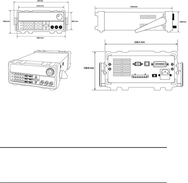
1.3 Product Dimensions
The 9201 and 9202 power supply’s dimensions are approximately 214.5 mm (8.44 in) x 88.2 mm (3.47 in) x 354.6 mm (13.96 in) (W x H x D). The 9205 and 9206 power supply’s dimensions are approximately 214.5 mm (8.44 in) x 88.2 mm (3.47 in) x 445 mm (17.52 in) (W x H x D).
Note: All dimensions in the figures below are measured in millimeters (mm).
1.4 Rackmount Installation
The instrument can be installed in a standard 19-inch rack using the optional IT-E151 rackmount kit. Below is an image of a 9200 Series model installed with the IT-E151 rackmount kit.
Note: Remove the carrying handle and the two plastic ears before mounting the instrument. To remove the handle, grasp the handle by its sides, pull outwards, and rotate it until the arrow on the handle and the arrow on the plastic ears are in opposite directions. Then pull the handle outward. After removing the handle, you can use a screwdriver to remove the two plastic ears.
2
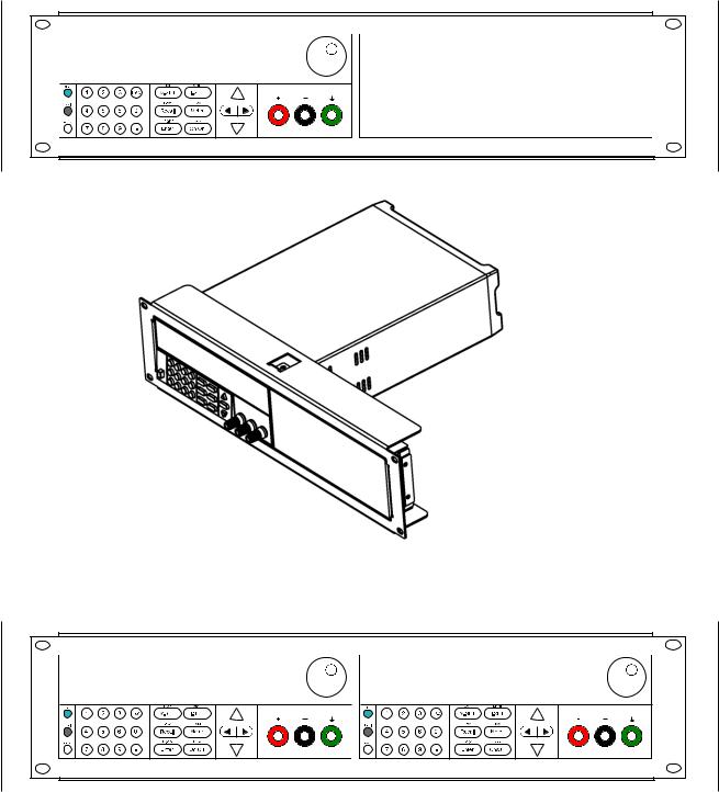
To rackmount a single instrument, order rackmount kit IT-E151
Side view of rackmounting a single instrument
To rackmount two instruments side-by-side, order rackmount kit IT-E151, the front cover panel is not needed.
3
1.5 Front Panel Overview
1
9
2 
3 
4 |
5 |
6 |
7 |
8 |
|
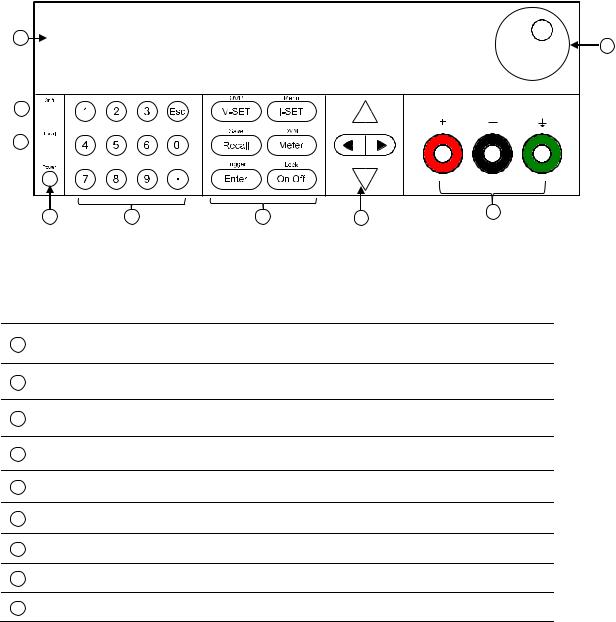
Figure 1 Front Panel View
Front Panel Description
1VFD display
2Shift key
3Local key
4Power key
5Numeric keys
6Function keys
7Cursor keys
8Output terminal
9Rotary knob
4

1.6 Keypad Overview
Figure 2 Keypad View
Keypad Description
Shift key
Enables access to secondary functions (Labeled in blue)
Local key
Sets the instrument back to local mode.
Power key
Power on the instrument.
Numeric keypad
~Enters numeric values for various parameters.
Vset / OVP button
Configures output voltage or sets the overvoltage protection point for the power supply.
Iset / Menu button
Configures output current or allows access to the power supply menu settings.
Recall / Save button
Saves and recalls instrument settings.
Meter / DVM button
Switches from set value display to metered output value display or switches to digital voltmeter function.
Enter / Trigger key
Confirms setting/parameter changes or used to trigger a list program.
Output / Lock button
Controls output On/Off state of the power supply or used to lock the front panel buttons.
Left/Right arrow keys
Adjusts cursor position or select menu items.
5
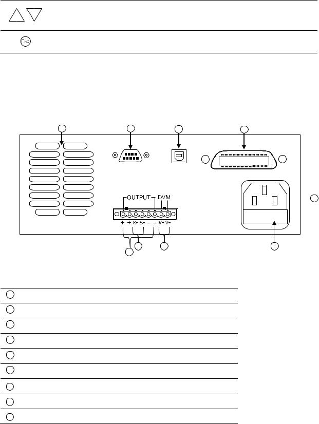
Up/Down arrow keys
Used to select menu items or increase/decrease output voltage or output current values.
Esc key
Cancel and return to previous menu.
1.7 Rear Panel Overview
1 |
2 |
3 |
4 |
 5
5
8 |
7 |
6 |
9
Rear Panel Description
1Cooling fan
2RS-232 interface
3USB interface
4GPIB interface
5AC power input receptacle
6Fuse box
7DVM input terminal
8Remote sense terminal
9Output terminal
6
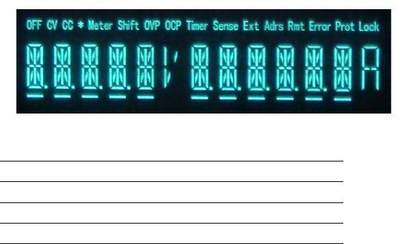
1.8 Display Overview
Display Description
OFF Indicates output is off
CV The power supply is in constant voltage mode
CC The power supply is in constant current mode
*Not used
Timer |
Indicates output on timer function is ON |
|
|
Sense |
Indicates remote sense |
|
|
Ext |
Not used |
|
|
Adrs |
Indicates remote communication activity |
|
|
Meter |
Indicates Meter ON state |
|
|
Shift |
Indicates shift mode (for access to secondary button functions) |
|
|
OVP |
Indicates overvoltage protection trip |
|
|
OCP |
Indicates overcurrent protection trip |
|
|
Rmt |
Indicates remote mode |
|
|
Error |
Indicates an error has occurred |
|
|
Prot |
Indicates protection trip for overvoltage or overtemperature |
|
|
Lock |
Indicates key lock is enabled |
|
|
7

2 Getting Started
Before connecting and powering up the instrument, please review and go through the instructions in this chapter.
2.1 Input Power and Fuse Requirements
Input Power
The supply has a selectable AC input that accepts line voltage input within:
Voltage: 110 V (+/- 10 %) or 220 V (+/- 10 %)
Frequency: 47 Hz – 63 Hz
Before connecting to an AC outlet or external power source, be sure that the power switch is in the OFF position and verify that the AC power cord, including the extension line, is compatible with the rated voltage/current and that there is sufficient circuit capacity for the power supply. Once verified, connect the cable firmly.
The included AC power cord is safety certified for this instrument operating in rated range. To change a cable or add an extension cable, be sure that it can meet the required power ratings for this instrument. Any misuse with wrong or unsafe cables will void the warranty.
SHOCK HAZARD:
The power cord provides a chassis ground through a third conductor. Verify that your power outlet is of the three-conductor type with the correct pin connected to earth ground.
8
 Loading...