


 Loading...
Model: 8600, 8601, 8602
Programmable DC Electronic Loads
USER MANUAL

Safety Summary
The following safety precautions apply to both operating and maintenance personnel and must be followed during all phases of operation, service, and repair of this instrument.
Before applying power to this instrument:
Read and understand the safety and operational information in this manual.
Apply all the listed safety precautions.
Verify that the voltage selector at the line power cord input is set to the correct line voltage. Operating the instrument at an incorrect line voltage will void the warranty.
Make all connections to the instrument before applying power.
Do not operate the instrument in ways not specified by this manual or by B&K Precision.
Failure to comply with these precautions or with warnings elsewhere in this manual violates the safety standards of design, manufacture, and intended use of the instrument. B&K Precision assumes no liability for a customer’s failure to comply with these requirements.
Category rating
The IEC 61010 standard defines safety category ratings that specify the amount of electrical energy available and the voltage impulses that may occur on electrical conductors associated with these category ratings. The category rating is a Roman numeral of I, II, III, or IV. This rating is also accompanied by a maximum voltage of the circuit to be tested, which defines the voltage impulses expected and required insulation clearances. These categories are:
Category I (CAT I): Measurement instruments whose measurement inputs are not intended to be connected to the mains supply. The voltages in the environment are typically derived from a limited-energy transformer or a battery.
Category II (CAT II): Measurement instruments whose measurement inputs are meant to be connected to the mains supply at a standard wall outlet or similar sources. Example measurement environments are portable tools and household appliances.
Category III (CAT III): Measurement instruments whose measurement inputs are meant to be connected to the mains installation of a building. Examples are measurements inside a building's circuit breaker panel or the wiring of permanently-installed motors.
i

Category IV (CAT IV): Measurement instruments whose measurement inputs are meant to be connected to the primary power entering a building or other outdoor wiring.
Do not use this instrument in an electrical environment with a higher category rating than what is specified in this manual for this instrument.
You must ensure that each accessory you use with this instrument has a category rating equal to or higher than the instrument's category rating to maintain the instrument's category rating. Failure to do so will lower the category rating of the measuring system.
Electrical Power
This instrument is intended to be powered from a CATEGORY II mains power environment. The mains power should be 120 V RMS or 240 V RMS. Use only the power cord supplied with the instrument and ensure it is appropriate for your country of use.
Ground the Instrument
To minimize shock hazard, the instrument chassis and cabinet must be connected to an electrical safety ground. This instrument is grounded through the ground conductor of the supplied, three-conductor AC line power cable. The power cable must be plugged into an approved three-conductor electrical outlet. The power jack and mating plug of the power cable meet IEC safety standards.
Do not alter or defeat the ground connection. Without the safety ground connection, all accessible conductive parts (including control knobs) may provide an electric shock. Failure to use a properly-grounded approved outlet and the recommended three-conductor AC line power cable may result in injury or death.
Unless otherwise stated, a ground connection on the instrument's front or rear panel is for a reference of potential only and is not to be used as a safety ground.
ii

Do not operate in an explosive or flammable atmosphere
Do not operate the instrument in the presence of flammable gases or vapors, fumes, or finelydivided particulates.
The instrument is designed to be used in office-type indoor environments. Do not operate the instrument
In the presence of noxious, corrosive, or flammable fumes, gases, vapors, chemicals, or finely-divided particulates.
In relative humidity conditions outside the instrument's specifications.
In environments where there is a danger of any liquid being spilled on the instrument or where any liquid can condense on the instrument.
In air temperatures exceeding the specified operating temperatures.
In atmospheric pressures outside the specified altitude limits or where the surrounding gas is not air.
In environments with restricted cooling air flow, even if the air temperatures are within specifications.
In direct sunlight.
This instrument is intended to be used in an indoor pollution degree 2 environment. The operating temperature range is 0 °C to 40 °C and the operating humidity range is ≤ 95% relative humidity with no condensation allowed.
Measurements made by this instrument may be outside specifications if the instrument is used in non-office-type environments. Such environments may include rapid temperature or humidity changes, sunlight, vibration and/or mechanical shocks, acoustic noise, electrical noise, strong electric fields, or strong magnetic fields.
Do not operate instrument if damaged
 If the instrument is damaged, appears to be damaged, or if any liquid, chemical, or other material gets on or inside the instrument, remove the instrument's power
iii

cord, remove the instrument from service, label it as not to be operated, and return the instrument to B&K Precision for repair. Notify B&K Precision of the nature of any contamination of the instrument.
Clean the instrument only as instructed
Do not clean the instrument, its switches, or its terminals with contact cleaners, abrasives, lubricants, solvents, acids/bases, or other such chemicals. Clean the instrument only with a clean dry lint-free cloth or as instructed in this manual.
Not for critical applications
This instrument is not authorized for use in contact with the human body or for use as a component in a life-support device or system.
Do not touch live circuits
Instrument covers must not be removed by operating personnel. Component replacement and internal adjustments must be made by qualified service-trained maintenance personnel who are aware of the hazards involved when the instrument's covers and shields are removed. Under certain conditions, even with the power cord removed, dangerous voltages may exist when the covers are removed. To avoid injuries, always disconnect the power cord from the instrument, disconnect all other connections (for example, test leads, computer interface cables, etc.), discharge all circuits, and verify there are no hazardous voltages present on any conductors by measurements with a properly-operating voltage-sensing device before touching any internal parts. Verify the voltage-sensing device is working properly before and after making the measurements by testing with known-operating voltage sources and test for both DC and AC voltages. Do not attempt any service or adjustment unless another person capable of rendering first aid and resuscitation is present.
Do not insert any object into an instrument's ventilation openings or other openings.
iv

Hazardous voltages may be present in unexpected locations in circuitry being tested when a fault condition in the circuit exists.
Fuse replacement
Fuse replacement must be done by qualified service-trained maintenance personnel who are aware of the instrument's fuse requirements and safe replacement procedures. Disconnect the instrument from the power line before replacing fuses. Replace fuses only with new fuses of the fuse types, voltage ratings, and current ratings specified in this manual or on the back of the instrument. Failure to do so may damage the instrument, lead to a safety hazard, or cause a fire. Failure to use the specified fuses will void the warranty.
Servicing
Do not substitute parts that are not approved by B&K Precision or modify this instrument. Return the instrument to B&K Precision for service and repair to ensure that safety and performance features are maintained.
Cooling fans
This instrument contains one or more cooling fans. For continued safe operation of the instrument, the air inlet and exhaust openings for these fans must not be blocked nor must accumulated dust or other debris be allowed to reduce air flow. Maintain at least 25 mm clearance around the sides of the instrument that contain air inlet and exhaust ports. If mounted in a rack, position power devices in the rack above the instrument to minimize instrument heating while rack mounted. Do not continue to operate the instrument if you cannot verify the fan is operating (note some fans may have intermittent duty cycles). Do not insert any object into the fan's inlet or outlet.
Do not short-circuit batteries
When using a DC load to discharge a battery, do not exceed the battery manufacturer's specified maximum rate of discharge.
v

Use correctly sized wires
To connect the load to the power supply, use a wire diameter large enough to handle the maximum continuous output short-circuit current of the power supply without the wire overheating.
For continued safe use of the instrument
Do not place heavy objects on the instrument.
Do not obstruct cooling air flow to the instrument.
Do not place a hot soldering iron on the instrument.
Do not pull the instrument with the power cord, connected probe, or connected test lead.
Do not move the instrument when a probe is connected to a circuit being tested.
vi

Compliance Statements
Disposal of Old Electrical & Electronic Equipment (Applicable in the European Union and other European countries with separate collection systems)
This product is subject to Directive 2002/96/EC of the European Parliament and the Council of the European Union on waste electrical and electronic equipment (WEEE) , and in jurisdictions adopting that Directive, is marked as being put on the market after August 13, 2005, and should not be disposed of as unsorted municipal waste. Please utilize your local WEEE collection facilities in the disposition of this product and otherwise observe all applicable requirements.
vii
CE Declaration of Conformity
The instrument meets the requirements of 2006/95/EC Low Voltage Directive and 2004/108/EC Electromagnetic Compatibility Directive with the following standards.
Low Voltage Directive
-EN61010-1: 2001
EMC Directive
-EN 61000-3-2: 2006
-EN 61000-3-3: 1995+A1: 2001+A2: 2005
-EN 61000-4-2 / -3 / -4 / -5 / -6 / -11
-EN 61326-1: 2006
viii
Safety Symbols
CAUTION indicates a hazardous situation which, if not avoided, could result in minor or moderate injury.
WARNING indicates a hazardous situation which, if not avoided, could result in death or serious injury.
Chassis (earth ground) symbol.
On (Power)
Off (Power)
On (Power). This is the In position of the power switch when instrument is ON.
Off (Power). This is the Out position of the power switch when instrument is OFF.
DANGER indicates a hazardous situation which, if not avoided, will result in death or serious injury.
WARNING indicates a hazardous situation which, if not avoided, could result in death or serious injury.
CAUTION indicates a hazardous situation which, if not avoided, could result in minor or moderate injury.
Safety instructions (or equivalent) signs indicate specific safetyrelated instructions or procedures.
ix
Table of Contents
Safety Summary................................................................................................... |
i |
||
|
Compliance Statements ............................................................................................................. |
vii |
|
|
CE Declaration of Conformity.................................................................................................... |
viii |
|
1 |
General Information..................................................................................... |
1 |
|
|
1.1 |
Product Overview ........................................................................................................... |
1 |
|
1.2 |
Package Contents............................................................................................................ |
2 |
|
1.3 |
Product Dimensions........................................................................................................ |
2 |
|
1.4 |
Rackmount Installation ................................................................................................... |
5 |
|
1.5 |
Front Panel Overview...................................................................................................... |
6 |
|
Front Panel Description........................................................................................................... |
6 |
|
|
1.6 |
Rear Panel Overview ....................................................................................................... |
7 |
|
Rear Panel Description ............................................................................................................ |
7 |
|
|
1.7 |
Display Overview............................................................................................................. |
8 |
|
Display Description.................................................................................................................. |
8 |
|
2 |
Getting Started........................................................................................... |
10 |
|
|
2.1 |
Input Power and Fuse Requirements............................................................................ |
10 |
|
Input Power........................................................................................................................... |
10 |
|
|
Fuse Requirements ................................................................................................................ |
11 |
|
|
Fuse Replacement ................................................................................................................. |
11 |
|
|
2.2 |
Input Connections......................................................................................................... |
12 |
|
2.3 |
Preliminary Check ......................................................................................................... |
13 |
|
Self-test Errors....................................................................................................................... |
13 |
|
|
Input Check............................................................................................................................ |
14 |
|
|
Check Model and Firmware Version ..................................................................................... |
15 |
|
3 |
Front Panel Operation ................................................................................ |
16 |
|
|
3.1 |
Menu Options ............................................................................................................... |
16 |
|
System Menu......................................................................................................................... |
16 |
|
|
Config Menu.......................................................................................................................... |
16 |
|
|
How to Navigate the Menu................................................................................................... |
17 |
|
|
3.2 |
Configure Operation Modes (CC/CV/CR/CW)............................................................... |
18 |
x
Constant Current (CC) Mode ................................................................................................. |
18 |
|
Constant Voltage (CV) Mode................................................................................................. |
20 |
|
Constant Resistance (CR) Mode ............................................................................................ |
22 |
|
Constant Power (CW) Mode.................................................................................................. |
23 |
|
Setting CC, CV, CR, CW Mode ................................................................................................ |
25 |
|
3.3 |
SYSTEM Menu ............................................................................................................... |
25 |
Restore Factory Default Settings........................................................................................... |
25 |
|
Configure Power-On State..................................................................................................... |
27 |
|
Load On Knob ........................................................................................................................ |
27 |
|
Configure Trigger Source....................................................................................................... |
27 |
|
Save/Recall Instrument Settings ........................................................................................... |
28 |
|
Display Input On Timer.......................................................................................................... |
31 |
|
Remote Interface Setup......................................................................................................... |
32 |
|
3.4 |
CONFIG Menu ............................................................................................................... |
35 |
Von Operation ....................................................................................................................... |
35 |
|
Configure Protection Settings ............................................................................................... |
38 |
|
Configure Timed Input .......................................................................................................... |
42 |
|
Measurement Configurations ............................................................................................... |
42 |
|
CR LED Function .................................................................................................................... |
44 |
|
Remote Sense........................................................................................................................ |
45 |
|
External Analog Control and Monitor ................................................................................... |
46 |
|
3.5 |
Short Operation ............................................................................................................ |
48 |
3.6 |
Transient Operation ...................................................................................................... |
49 |
Continuous ............................................................................................................................ |
49 |
|
Pulse ...................................................................................................................................... |
50 |
|
Toggle.................................................................................................................................... |
50 |
|
3.7 |
List Operation................................................................................................................ |
54 |
Configure List ........................................................................................................................ |
55 |
|
Run List.................................................................................................................................. |
57 |
|
3.8 |
Battery Test Function .................................................................................................... |
58 |
3.9 |
Test Operations ............................................................................................................. |
59 |
Automatic Test Function........................................................................................................ |
59 |
|
OCP Test Function.................................................................................................................. |
69 |
|
|
|
xi |
|
OPP Test Function.................................................................................................................. |
72 |
|
|
3.10 |
Key Lock......................................................................................................................... |
75 |
4 |
Remote Operation...................................................................................... |
76 |
|
|
4.1 |
Interface Connection..................................................................................................... |
76 |
|
RS-232 ................................................................................................................................... |
76 |
|
|
GPIB |
....................................................................................................................................... |
77 |
|
USBTMC................................................................................................................................. |
77 |
|
|
4.2 |
Remote Commands....................................................................................................... |
77 |
5 |
Troubleshooting Guide ............................................................................... |
78 |
|
|
General.................................................................................................................................. |
78 |
|
|
Remote Control ..................................................................................................................... |
78 |
|
6 |
Specifications ............................................................................................. |
80 |
|
|
Supplementary Characteristics ................................................................................................. |
82 |
|
7 |
Calibration.................................................................................................. |
84 |
|
Index................................................................................................................. |
|
85 |
|
xii
1 General Information
1.1 Product Overview
The 8600 Series DC Electronic Loads are versatile instruments used for static and dynamic testing of DC power supplies, batteries, DC-to-DC converters, and battery chargers. Other applications include fuel-cell and photovoltaic cell test.
The DC load can be used in one of the following operation modes: constant voltage (CV), constant current (CC), constant resistance (CR), or constant power (CW). A wide range of dynamic loading applications can be simulated through user-programmable slew rates, load levels, duration, and conducting voltage. The DC load can be remotely programmed via the USB, GPIB, or RS-232 serial interface. Versatile triggering options allow the dynamic load behavior to be synchronized with other events.
A battery test mode is provided that will measure the ampere-hour (Ah) characteristic of a battery. Shorts can be simulated by either the front panel or custom programming. The DC source or other components can be protected from excessive voltage, current, or power, which will cause the DC load to shut down if excessive levels or reverse polarity are detected.
Features:
CC/CV/CR/CW operating modes
High Resolution Display
Transient mode up to 25 kHz
List mode function
Measurement speed up to 50 kHz
Remote sense function
Built-in battery test function
OCP and OPP auto test function
CR-LED function
Store/recall up to 100 setups
RS232/USBTMC/GPIB interfaces
Analog current control and monitoring
Adjustable slew rate in CC mode
OVP/OCP/OPP/OTP and reverse voltage protection
1
1.2 Package Contents
Please inspect the instrument mechanically and electrically upon receiving it. Unpack all items from the shipping carton, and check for any obvious signs of physical damage that may have occurred during transportation. Report any damage to the shipping agent immediately. Save the original packing carton for possible future reshipment. Every instrument is shipped with the following contents:
1x 8600 series DC Electronic load
1x User Manual
1x AC Power Cord
Certificate of Calibration
Test Report
Verify that all items above are included in the shipping container. If anything is missing, please contact B&K Precision.
1.3 Product Dimensions
All models are designed to fit in a standard 19-inch rackmount. The dimensions are shown in Figure 1 below.
2
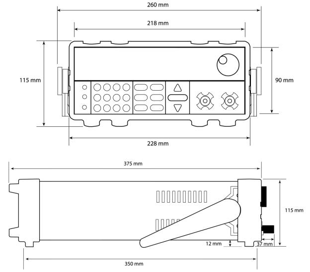
Figure 1 – Front and Side View
3
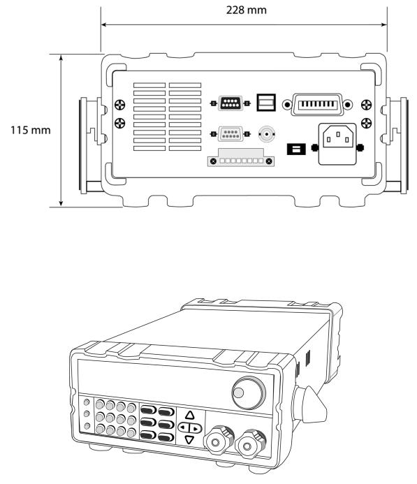
Figure 2 - Rear View
4
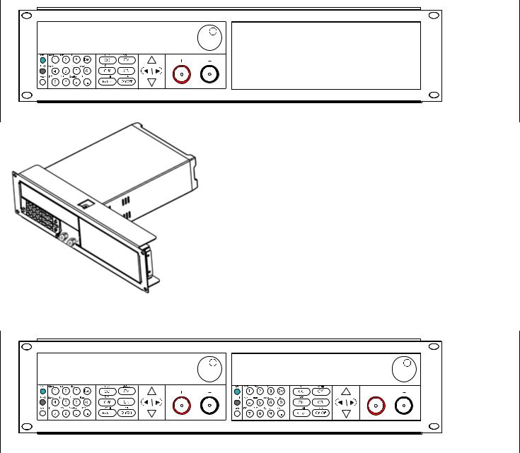
1.4 Rackmount Installation
The instrument can be installed in a standard 19 inch rack. The optional rackmount kit IT-E151 is required. Below is an image of a model installed with the IT-E151 rackmount kit.
This rackmount kit will allow up to two models installed side by side, as shown below.
5

1.5 Front Panel Overview
14
13
15
3 

2 

1 |
4 |
5 |
6 |
7 |
8 |
9 |
10 |
11 |
12 |
Figure 3 - Front Panel
Front Panel Description
1Power On/Off switch
2Local button
3Shift button
4Numeric keypad
5CC/OCP button
6CW/OPP button
7Enter/Recall settings button
8Input On/Off and key lock button
9CR button
10CV/Setup button
11Navigation arrow keys
12Input terminal
13Rotary knob
14VFD display
15ESC button
6
1.6 Rear Panel Overview
1 |
2 |
3 |
|
|
4 |
5 |
6 |
|
|
|
|
|
|
|
7 |
|
|
|
|
|
|
9 |
8 |
|
14 |
13 |
12 |
11 |
10 |
|
|
Figure 4 - Rear Panel
Rear Panel Description
1Cooling fan vent
2Remote control port (not used)
3RS232 Interface
4Current Monitor BNC output
5USB Interface
6GPIB Interface
7AC input receptacle
8Fuse box
9Line voltage selector
10 |
Voltage fault (VF) output terminal |
|
11Input On/Off (ON) control terminal
12External trigger input terminals
13External programming input terminals
14Remote sense terminals
7

1.7 |
Display Overview |
|
|
|
|
|
||||
|
|
|
|
|
|
|
|
|
|
|
|
|
|
|
|
|
|||||
|
OFF CC CV CR CW Rmt Addr SRQ Error |
|
Trig Sense |
Prot Rear Auto |
|
|||||
|
|
|
|
|
|
|
||||
|
|
80.000V |
|
|
12.000A |
|
||||
|
|
|
0.0W |
|
|
CC = 85.000 V |
|
|
||
|
|
|
|
|
||||||
|
|
|
|
|
|
|
|
|
|
|
|
|
|
|
|
|
|
|
|
|
|
1 |
2 |
|
|
3 |
4 |
|
|
|||
Figure 5 – Display Screen
Display Description
1Measured input voltage
2Measured input power
3Settings Display
Displays parameter settings such as CC, CV, CR, CW
4Measured input current
OFF Indicates input is disabled
CC Indicates constant current (CC) operation
CV Indicates constant voltage (CV) operation
CR Indicates constant resistance (CR) operation
CW Indicates constant power (CW) operation
Rmt Indicates remote mode
Addr Indicates remote communication activity
SRQ SRQ service request indicator
Error Indicates an error has occurred
Trig Indicates waiting for trigger
Sense Indicates remote sense enabled
Prot
Indicates protection trip for over voltage, over power, or over current
8

Rear Indicates external analog control is enabled.
Auto Indicates voltage auto range is enabled.
*Indicates key lock is enabled
Shift
Indicates shift mode (for access to secondary button functions)
9
2 Getting Started
Before connecting and powering up the instrument, please review and go through the instructions in this chapter.
2.1 Input Power and Fuse Requirements
Input Power
The load has a selectable AC input that accepts line voltage input within:
Voltage: 115 V (+/-10%) or 230 V (+/- 10 %)
Frequency: 47 Hz – 63 Hz
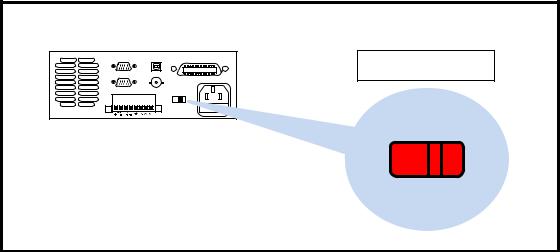
Use the line voltage selector switch in the back to switch between 110 V and 220 V operation.
110 or 220 Switch |
| <![if ! IE]> <![endif]>110 |
Figure 6 - Line Voltage Switch Location
10

Disconnect all cables including the power cord from the instrument when changing the instrument's line voltage. After changing the line voltage setting, ensure the instrument has fuses of the proper ratings and types for the selected line voltage before applying line power.
Fuse Requirements
An AC input fuse is necessary when powering the instrument. Below is a table of the fuse required for all models operating with either 110 VAC or 220 VAC input.
Table 1 - Fuse Requirements
Model |
Fuse Specification (110 VAC) |
Fuse Specification (220 VAC) |
8600 |
T 1.25 A, 250 V |
T 500 mA, 250 V |
8601 |
T 1.25 A, 250 V |
T 500 mA, 250 V |
8602 |
T 1.25 A, 250 V |
T 500 mA, 250 V |
Fuse Replacement
Follow the steps below to replace or check the fuse.
1.Locate the fuse box next to the AC input connector in the rear panel.
2.With a small flat blade screwdriver, insert into the fuse box slit to pull and slide out the fuse box as indicated below.
3.Check and replace fuse (if necessary) for the desired line voltage operation.
11

Fuse box slit
Fuse |
|
box |
Check/Remove Fuse |
Figure 7 - Fuse Box
2.2 Input Connections
The main DC input terminal is a screw type binding post terminal located in the front panel. To loosen, turn the terminal cap counter-clock wise.
Note: The screws on the terminals can be completely removed to allow for ring type adapters (must be greater than 6mm in diameter).
Due to the high current rating of the DC load, proper wire sizes are necessary for safe connectivity and to prevent wires from overheating.
Before connecting wires to the input terminals, turn OFF the load to avoid damage to the instrument and the device under test (DUT). For safety, wires must have a wire gauge size large enough to prevent overheating when the load operates at maximum rated current. It will also minimize large voltage drops from resistances in the wires.
12

2.3 Preliminary Check
Complete the following steps to verify that the load is ready for use.
1.Verify AC Input Voltage
Verify and check to make sure proper AC voltages are available to power the instrument.
The AC voltage range must meet the acceptable specification as explained in “2.1 Input Power and Fuse Requirements”.
Check to verify that the unit is configured to operate at the AC input voltage level of the power source. If not, it will damage the unit and void its warranty.
2.Connect Power and Self Test
Connect AC power cord to the AC receptacle in the rear panel and press the power
switch to the |(  ) ON position to turn ON the instrument. It will run through a self test procedure with the screen shown below:
System Selftest . . . .
. .
Self-test Errors
The following errors will be displayed if self-test did not complete successfully:
13
|
Table 2 - Self-test Messages |
|
|
Error Message on Display |
Description |
EEPROM FAILURE |
The internal EEPROM is corrupted or damaged. |
Config Data Lost |
The last operation data within the EEPROM is lost. |
Calibration Data Lost |
Calibration data within the EEPROM is lost. |
FactoryCal.Data Lost |
Factory calibration data is lost. |
MainframeInitialize Lost |
The system settings within the EEPROM is lost. |
If any of these errors occur, please contact B&K Precision.
Input Check
Follow the steps below to check that the load is operating correctly. A DC power supply rated for at least 5V and 1 A will be required to proceed with this check.
1.Power on the load. The display will show the OFF annunciator above the voltage display.
2.Connect the input terminal to a DC power supply and configure the supply to output 5 V and current limit to 1 A.
3.Turn on the DC power supply’s output. Observe the load’s measured voltage display, which should read close to or exactly 5.000V.
4.Press  so that its back light turns on, and enter 0.500 A using the numeric keypad. Press
  .
.
5.The display should show CC = 0.500A on the bottom right.
6.Press  and its backlight will be lit. The OFF indicator will change to CC and the measured current should now display a value close to 0.500 A.
7.This setup verifies that the load is drawing power correctly from the power supply.
Note: If the load is not drawing power from the DC power supply, check all load protection limits and settings within the menu to verify that the load is configured to allow drawing power at 5V, 0.500 A. Also, verify that the CC mode parameters
are setup to operate within the configured valid ranges by pressing |
and |
. |
|
|
|
14
Check Model and Firmware Version
The model and firmware version can be verified by using the *IDN? query remote command. It can also be found from the front panel:
1. |
Press |
and press |
. |
2. |
The display will show the following: |
||
0.000V 0.000A
8600 Ver : 1.29 – 1.36
3.The model is shown above as 8600, and the firmware version is shown as 1.29-1.36.
4.Press  once to return to the normal display.
15
3 Front Panel Operation
3.1 Menu Options
Most settings and parameters can be configured from the built-in menu systems of the instrument. There are two main menus: System and Config.
System Menu
To access the system menu, press then  .
.
The system menu will have the following options:
Initialize |
Reset load settings to factory default values. |
Power-On |
Configure power-on state. |
Buzzer |
Enable/Disable key sound. |
Knob |
Controls update method when using knob to control load. |
Trigger |
Configure Trigger. |
Memory |
Select memory location for save/recall instrument settings. |
Displ (Display) |
Enable/Disable load ON timer. |
Communication |
Select communication interface. |
Protocol |
Select standard SCPI or extended set of protocols for remote |
|
communication. |
Config Menu
To access the system menu, press then  .
.
The system menu will have the following options:
Von
Protect
Measure
CR_LED
Remote-Sense
Ext-Program
Configures Von function
Configures protection parameters and limits Configures measurement parameters Enables/Disables CR LED function Enables/Disables remote sense Enables/Disables external analog control
16
Loading...