


 Loading...
Model 2831E , 5491B
4 ½ Digit and 50,000 Count Bench
Multimeters
USER MANUAL
Notice
The information contained in this document is subject to change without notice.
Safety Notice Supplement
As described in the International Electrotechnical Commission (IEC) Standard IEC 664, digital multimeter measuring circuits (e.g., B&K Models 2831E and 5491B) and the USB terminal are Installation Category II (CATII). The AC input terminal is rated CAT I.
This equipment is POLLUTION DEGREE 2, INDOOR USE product.
Safety Summary
The following safety precautions apply to both operating and maintenance personnel and must be observed during all phases of operation, service, and repair of this instrument. Before applying power, follow the installation instructions and become familiar with the operating instructions for this instrument.
GROUND THE INSTRUMENT
To minimize shock hazard, the instrument chassis and cabinet must be connected to an electrical ground. This instrument is grounded through the ground conductor of the supplied, three-conductor ac power cable. The power cable must be plugged into an approved three-conductor electrical outlet. Do not alter the ground connection. Without the protective ground connection, all accessible conductive parts (including control knobs) can render an electric shock. The power jack and mating plug of the power cable meet IEC safety standards.
DO NOT OPERATE IN AN EXPLOSIVE ATMOSPHERE
Do not operate the instrument in the presence of flammable gases or fumes. Operation of any electrical instrument in such an environment constitutes a definite safety hazard.
KEEP AWAY FROM LIVE CIRCUITS
Instrument covers must not be removed by operating personnel. Component replacement and internal adjustments must be made by qualified maintenance personnel. Disconnect the power cord before removing the instrument covers and replacing components. Under certain
2
conditions, even with the power cable removed, dangerous voltages may exist. To avoid injuries, always disconnect power and discharge circuits before touching them.
DO NOT SERVICE OR ADJUST ALONE
Do not attempt any internal service or adjustment unless another person, capable of rendering first aid and resuscitation, is present.
DO NOT SUBSTITUTE PARTS OR MODIFY THE INSTRUMENT
Do not install substitute parts or perform any unauthorized modifications to this instrument. Return the instrument to B&K Precision for service and repair to ensure that safety features are maintained.
WARNINGS AND CAUTIONS
WARNING and CAUTION statements, such as the following examples, denote a hazard and appear throughout this manual. Follow all instructions contained in these statements.
A WARNING statement calls attention to an operating procedure, practice, or condition, which, if not followed correctly, could result in injury or death to personnel.
A CAUTION statement calls attention to an operating procedure, practice, or condition, which, if not followed correctly, could result in damage to or destruction of parts or the entire product.
WARNING:Do not alter the ground connection. Without the protective ground connection, all accessible conductive parts (including control knobs) can render an electric shock. The power jack and mating plug of the power cable meet IEC safety standards.
WARNING:To avoid electrical shock hazard, disconnect power cord before removing covers. Refer servicing to qualified personnel.
CAUTION: Before connecting the line cord to the AC mains, check the rear panel AC line voltage indicator. Applying a line voltage other than the indicated voltage can destroy the AC line fuses. For continued fire protection, replace fuses only with those of the specified voltage and current ratings.
CAUTION: This product uses components which can be damaged by electro-static discharge (ESD). To avoid damage, be sure to follow proper procedures for handling, storing
and transporting parts and subassemblies which contain ESD-sensitive components.
3
SAFETY SYMBOL
This symbol on an instrument indicates that the user should refer to the operating instructions located in the manual.
Electrical Shock hazard.
Chassis ground symbol.
CAT I IEC Measurement Category II.
(1000V) Inputs may be connected to mains (up to 300 VAC) under
Category II overvoltage conditions.
CAT II IEC Measurement Category II.
(300V) Inputs may be connected to mains (up to 300 VAC) under Category II overvoltage conditions.
Compliance Statements
Disposal of Old Electrical & Electronic Equipment (Applicable in the European Union and other European countries with separate collection systems)
This product is subject to Directive 2002/96/EC of the European Parliament and the Council of the European Union on waste electrical and electronic equipment (WEEE) , and in jurisdictions adopting that Directive, is marked as being put on the market after August 13, 2005, and should not be disposed of as unsorted municipal waste. Please utilize your local WEEE collection facilities in the disposition of this product and otherwise observe all applicable requirements.
4
Table of Contents
Notice................................................................................................................................................... |
|
2 |
Safety Notice Supplement.................................................................................................................... |
2 |
|
Safety Summary................................................................................................................................... |
2 |
|
Chapter 1 General Information........................................................................................................ |
8 |
|
1.1 |
Feature Overview......................................................................................................................................... |
8 |
1.2 |
Incoming Inspection .................................................................................................................................... |
8 |
Chapter 2 Overview .......................................................................................................................... |
9 |
|
2.1 |
Front Panel Overview .................................................................................................................................. |
9 |
2.2 Annunciators on Screen ............................................................................................................................. |
10 |
|
2.3 |
Front Panel Menu Reference ...................................................................................................................... |
11 |
2.4 |
Front Panel Menu Overview...................................................................................................................... |
12 |
2.5 |
Rear Panel Summary ................................................................................................................................. |
13 |
2.6 Power up.................................................................................................................................................... |
14 |
|
|
2.6.1 Power Line Connection.............................................................................................................. |
14 |
|
2.6.2 Input Terminals ............................................................................................................................ |
14 |
|
2.6.3 Power-up Sequence ................................................................................................................... |
16 |
|
2.6.4 High Energy Circuit Safety Precautions .................................................................................. |
16 |
|
2.6.5 Power-on Defaults....................................................................................................................... |
17 |
|
2.6.6 Warm-up time .............................................................................................................................. |
17 |
2.7 |
Display....................................................................................................................................................... |
17 |
Chapter 3 Basic Measurements.................................................................................................... |
18 |
|
3.1 |
Preparation................................................................................................................................................. |
18 |
3.2 Measuring Voltage ..................................................................................................................................... |
18 |
|
|
3.2.1 Connections ................................................................................................................................. |
18 |
3.3 |
Measuring Current..................................................................................................................................... |
19 |
|
3.3.1 Connections ................................................................................................................................. |
20 |
|
3.3.2 Front Panel Fuse Replacement ................................................................................................ |
22 |
3.4 |
Measuring Resistance ................................................................................................................................ |
23 |
|
3.4.1 Connections ................................................................................................................................. |
23 |
3.5 |
Measuring Frequency and Period .............................................................................................................. |
24 |
|
3.5.1 Trigger Level and Measurement Errors ................................................................................... |
24 |
|
3.5.2 Gate Time..................................................................................................................................... |
24 |
|
3.5.3 Connections ................................................................................................................................. |
24 |
3.6 |
Measuring Continuity ................................................................................................................................ |
25 |
|
3.6.1 Connections ................................................................................................................................. |
26 |
3.7 Testing Diode............................................................................................................................................. |
26 |
|
|
3.7.1 Connections ................................................................................................................................. |
26 |
3.8 Measuring True RMS AC+DC .................................................................................................................. |
27 |
|
|
3.8.1 Connections ................................................................................................................................. |
27 |
|
3.8.2 Using the 2nd parameter display ............................................................................................... |
28 |
3.9 |
Math Functions .......................................................................................................................................... |
29 |
|
3.9.1 Percent ......................................................................................................................................... |
29 |
|
5 |
|
3.9.2 dB Calculation.............................................................................................................................. |
30 |
3.9.3 dBm Calculation .......................................................................................................................... |
31 |
Chapter 4 Measurement Options.................................................................................................. |
33 |
4.1 Measurement configuration ....................................................................................................................... |
33 |
4.1.1 Range ........................................................................................................................................... |
33 |
4.1.2 Relative......................................................................................................................................... |
34 |
4.1.3 Rate............................................................................................................................................... |
34 |
4.2 Trigger Operations..................................................................................................................................... |
35 |
4.2.1 Trigger procedure........................................................................................................................ |
35 |
4.2.2 Reading Hold ............................................................................................................................... |
36 |
4.3 MAX / MIN ............................................................................................................................................... |
36 |
4.4 Limit Operations........................................................................................................................................ |
36 |
4.4.1 Enabling limits.............................................................................................................................. |
37 |
4.4.2 Setting Limit Values .................................................................................................................... |
37 |
4.5 System Operations..................................................................................................................................... |
37 |
4.5.1 Beeper Control ............................................................................................................................ |
38 |
4.5.2 Baud rate...................................................................................................................................... |
38 |
4.5.3 Selecting the Terminal Character.............................................................................................. |
39 |
4.5.4 Key Sound.................................................................................................................................... |
40 |
Chapter 5 Remote Operation ........................................................................................................ |
41 |
5.1 USB & RS232 ........................................................................................................................................... |
41 |
5.2 Serial Interface Operation.......................................................................................................................... |
41 |
5.2.1 USB interface configured as virtual COM RS232 interface.................................................. |
41 |
5.2.2 Sending and receiving data....................................................................................................... |
41 |
5.2.3 Selecting Baud Rate................................................................................................................... |
41 |
5.2.4 Software Protocol........................................................................................................................ |
42 |
5.3 Data Format ............................................................................................................................................... |
42 |
Chapter 6 SCPI Command Reference ........................................................................................ |
43 |
6.1 Command structure.................................................................................................................................... |
43 |
6.2 Command Syntax....................................................................................................................................... |
43 |
6.2.1 Commands and command parameters ................................................................................... |
43 |
6.2.2 Short-form Rules ......................................................................................................................... |
45 |
6.2.3 Basic Rules of Command Structure ......................................................................................... |
45 |
6.2.4 Multiple Command Rules........................................................................................................... |
46 |
6.2.5 Command Path Rules ................................................................................................................ |
46 |
6.3 Command Reference ................................................................................................................................. |
46 |
6.3.1 DISPlay subsystem..................................................................................................................... |
46 |
6.3.2 FUNCtion subsystem.................................................................................................................. |
48 |
6.3.3 VOLTage subsystem................................................................................................................... |
49 |
6.3.4 CURRent subsystem .................................................................................................................. |
53 |
6.3.5 RESistance subsystem .............................................................................................................. |
57 |
6.3.6 FREQuency and PERiod subsystem ....................................................................................... |
60 |
6.3.7 TRIGger subsystem.................................................................................................................... |
62 |
6.3.8 FETCH Subsystem ..................................................................................................................... |
63 |
6 |
|
6.3.9 SYSTem Subsystem................................................................................................................... |
63 |
6.3.10 Common Commands ............................................................................................................... |
64 |
Chapter 7 Specifications ................................................................................................................ |
65 |
SERVICE INFORMATION............................................................................................................... |
73 |
LIMITED WARRANTY.................................................................................................................... |
74 |
7
Chapter 1 General Information
1.1Feature Overview
The 2831E 4½ digit and 5491B 50,000 count multimeters provide measurements with high accuracy, great stability and fast measurement rates. The meters provide a maximum measurement rate of 25 readings/sec and a 0.02% and 0.03% DC voltage basic accuracy for model 5491B and 2831E respectively. Both meters have broad measurement ranges:
DC voltage from 50 μV to 1000 V
AC (RMS) voltage from 1 mV to 750 V
DC current from 100 nA to 20 A
AC (RMS) current from 100n A to 20 A
Two -wire resistance from 10 mΩ to 20 MΩ (50 MΩ for model 5491B)
Frequency from 5 Hz to 1 MHz
Some additional capabilities:
Full range of functions: In addition to those listed above, the meter functions include period, dB, dBm, continuity, diode testing, max, min and percent.
Programming languages and remote control interfaces: The meters are programmable via USB (Virtual COM) interface using SCPI commands
1.2Incoming Inspection
Please inspect the instrument mechanically and electrically upon receiving it. Unpack all items from the shipping carton, and check for any obvious signs of physical damage that may have occurred during transportation. Report any damage to the shipping agent immediately. Save the original packing carton for possible future reshipment. The following items are included with every order:
Multimeter
Test leads
Power cord
Spare fuse
Operation Manual
Calibration certificate and test report
Verify that all items above are included in the shipping container. If anything is missing, please contact B&K Precision.
8
Chapter 2 Overview
2.1Front Panel Overview
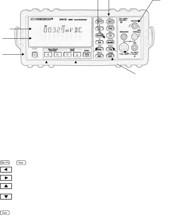
The front panel of the multimeter is shown in Figure 2-1. This figure includes some important abbreviated information that should be reviewed before operating the instrument.
Primary
Display 
Secondary
Display
On /off
Switch
2. Math function key |
1. Function keys |
|
|
|
|
|
|
|
|
|
|
|
|
|
|
|
|
|
|
|
|
|
|
|
|
|
|
|
|
|
|
|
|
|
|
|
|
|
|
|
|
5. Range |
4. Menu |
3. 2nd Display |
7. |
|
Shift/local |
6. Hold/Trig |
|||
|
|||||||||
Selection |
Operation |
And speed key |
|
Key |
Key |
||||
Figure 2-1 Front Panel
Input terminals
Current
Input fuse
1.Measurement Function keys (shifted and unshifted)
Select measurement function: DC voltage and current, AC voltage and current, resistance, continuity, frequency, period, dB, dBm, True RMS AC+DC and diode test.
2.Math function keys
Select the math function: Rel, %, Max/Min, Comp and Hold.
3.2nd Display and speed key
 Changes reading rate: Fast, Medium and Slow.
 →
→  turns on/ off the 2nd parameter display.
4.Menu operation keys
→ |
Open/Close menu |
Move through selections within menu level, command level or parameter level Move through selections within menu level, command level or parameter level. Move up a level.
Move down a level.
 (ENTER) Save the change made on “parameter” level, and return to the “command” level. Cancel the change made on “parameter” level, and return to the “command” level.
9

5.Range and Combination function selecting keys
Select a 2nd display parameter
Select a 2nd display parameter
Select a higher range and disable auto ranging.
Select a lower range and disable auto ranging.
Toggle between auto ranging and manual ranging.
6.Trig/Hold Key
Trig |
|
Trigger a measurement from the front panel. |
|
|
|
|
Trig |
Hold a reading on the display. |
|
|
7.Shift/Local keys
Used to access shifted keys.
 (LOCAL) Cancel remote control mode and back to the LOCAL mode.
2.2Annunciators on Screen
|
Figure 2-2 Display Annunciators |
FAST |
Fast reading rate |
MED |
Medium reading rate |
SLOW |
Slow reading rate |
TRIG |
Indicates trigger (front panel, bus) selected. |
HOLD |
Reading HOLD function is enabled |
REL |
Relative reading displayed |
MATH |
A math operation is enabled (%, dB, dBm). |
(Speaker) |
Beeper on for continuity testing function |
(Diode) |
Instrument is in diode testing function |
DC |
DC operation is enabled |
AC |
AC operation is enabled |
COMP |
Limit testing function is enabled |
|
10 |
HI/IN/LO |
Indicates the limit testing results |
RMT |
Multimeter is in remote control mode |
AUTO |
Auto ranging enabled |
Max/Min |
MAX / MIN operation is enabled |
ERR |
Hardware or remote control error detected |
SHIFT |
Accessing shifted keys |
2.3Front Panel Menu Reference
A MATH MENU
1: HI LIMIT → 2: LO LIMIT → 3: PERC REF → 4: dB REF→ 5: dBm REF
1. |
HI LIMIT |
Set the high limit for limit testing. |
||
2. |
LO LIMIT |
Set the low limit for limit testing. |
||
3. |
PERC REF |
Set the reference value for PERCENT function |
||
4. |
dB REF |
Set the dB reference voltage value. |
||
5. |
dBm REF |
Set the dBm reference impedance value. |
||
B TRIGGER MENU |
|
|
||
|
1: TRIG MOD |
|
|
|
1. |
TRIG MOD |
Select IMMediate, Manual or Bus trigger source mode. |
||
C SYSTEM MENU
1: BEEP STA → 2: BAUD RAT → 3: TX TERM → 4: RETURN → 5: KEY SONG → 6: REVISION
1. |
BEEP STA |
Enable or disable the beeper function |
2. |
BAUD RAT |
Select the baud rate for USB (virtual COM) or RS232 (Model 5491B only) |
|
operation. |
|
3. |
TX TERM |
Set the terminal character for USB (virtual COM) or RS232 (Model 5491B |
|
|
only) operation, which identifies the end of a command string |
4. |
RETURN |
Sets whether to enable Echo of the “sent” SCPI commands in return string. |
|
|
(i.e. if ON, sending *IDN? will return with *IDN? and model information on |
|
|
two separate lines). |
5. |
KEY SONG |
Enable or disable the key sound when you press a key. |
6. |
REVISION |
Shows the model number and firmware version of the instrument. |
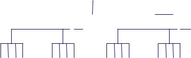
2.4Front Panel Menu Overview
The menu is organized in a top-down tree structure with three levels (menus, commands and
parameters) as shown in Figure 2-3. You can use down ( ) or up (
 ) to move menu tree from one level to another. Each of the three levels has several horizontal choices which you can view by using
left ( ) or right (
 ).
).
Menus 

Commands
Parameters
Figure 2-3 Menu Tree
To turn on the menu, press  →
→ (Menu).
To turn off the menu, press  →
→ (Menu), or press any of the function or math keys on the front panel.
To confirm a change on the “parameter” level, press  (ENTER).
To cancel a change on the “parameter” level, press  (Menu).
Note: If you press  on the “menu” level, this is the top level of the menu and you cannot
go any higher; similarly if you press  on the “parameter” level, this is the bottom level of the menu and you cannot go any lower.
12
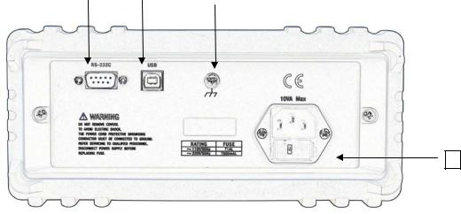
2.5Rear Panel Summary
The rear panel of the multimeter is shown in Figure 2-4. This section includes important information that should be reviewed before operating the instrument.
4 |
|
1 |
|
2 |
|
|
|
|
|
3
Figure 2-4 Rear Panel
1.USB Device Port
Connection port for USB remote control.
2.Grounding
Chassis Grounding terminal
3.Power-Line Fuse-Holder Assembly
The multimeter can be configured for line voltage of 110/220 V ± 10% AC at line frequency of 50/60 Hz ± 5%.
Power-line fuse is used for instrument protection. (220 V/500 mA or 110 V/1 A)
Note: Please use the same-type fuse. To verify and replace the fuse, remove the power cable and pull out the fuse holder. To select between line voltage operations of 110 V or 220 V, turn the grey colored fuse holder until the correct line voltage label is shown on the outer window of the fuse holder. It should say “110” or “220” depending which way you turn it.
4.RS232 Communication Port (Model 5491B only) Connection port for remote control via RS232.
13
2.6Power up
2.6.1Power Line Connection
Follow the procedure below to connect the multimeter to line power and turn on the instrument.
1.Check to make sure that the line voltage is in the correct range of 110 V or 220 V ± 10% (198 V to 242 V) and line frequency is in the range of 60 Hz or 50 Hz ± 5% (or 47.5 to 52.5 Hz) and that the line voltage switch is in the correct position before connecting the power cord. To check, first look at the label on the fuse compartment to verify if it is shown as “110” or “220”. If it is not switched to the correct one, open up the fuse compartment and turn the grey fuse holder until it shows the correct voltage label (110 or 220) on the outer part of the fuse compartment. Then, check to make sure correct fuse value is used for the selected voltage operation.
CAUTION: Operating the instrument on an incorrect voltage may cause damage to the instrument, possibly voiding the warranty.
2.Before plugging in the power cord, make sure that the front panel power switch is in the off position.
3.Connect the female end of the supplied power cord to the AC receptacle on the rear panel. Connect the other end of the power cord to a grounded AC outlet.
WARNING: The power cord supplied with the multimeter contains a separate ground wire for use with grounded outlets. When proper connections are made, instrument chassis is connected to power line ground through the ground wire in the power cord. Failure to use a grounded outlet may result in personal injury or death due to electric shock.
4.Turn on the instrument by pressing the front panel power switch and instrument is ready for measuring.
2.6.2Input Terminals
The input terminals are shown in Figure 2-5. The multimeter is protected against overloads up to the limits as shown in table 2-1. Exceeding these limits may result in a hazard to both the multimeter and operator.
14
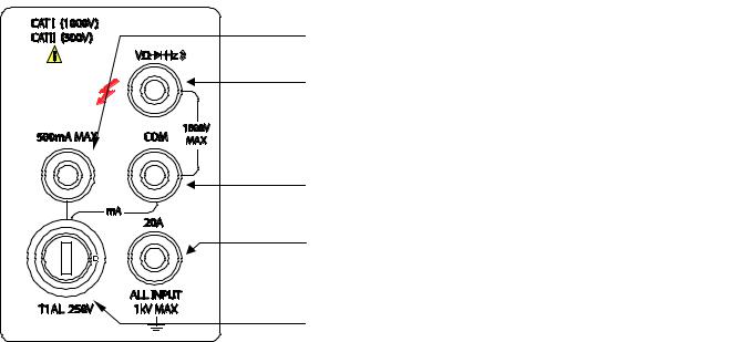
2 mA-200 mA for 2831E, 5 mA-500 mA for model 5491B range DC/AC current input terminal for DC/AC current
Input-High terminal for Volts, ohms, Hz, period, diode and continuity measurements
Common terminal
2 A (5 A for model 5491B) and 20 A range current input terminal for DC/AC current measurement
T1AL/250 V type fuse for the mA measurement range
Figure 2-5 Input terminals
15
Table 2-1 Input protection Limits
Function |
Input Terminals |
Maximum Allowable Input |
DCV |
to COM |
1010V DC |
ACV,HZ |
to COM |
757.5V AC RMS,1000V Peak |
mA, HZ |
500mA to COM |
200mA (Model 5491B: 500 mA) DC |
|
|
or AC RMS |
20A,HZ |
20A to COM |
20A DC or AC RMS |
Ω |
to COM |
500V DC or AC RMS |
, |
to COM |
500V DC or AC RMS |
All functions |
Any terminals to earth |
1000V DC or 1000V peak AC |
2.6.3Power-up Sequence
On power-up, the multimeter performs self-tests on its EPROM and RAM and lights all segments and annunciators for about 1 second. If a failure is detected, the instrument momentarily displays an error message and the ERR annunciator turns on.
If the instrument passes self-tests, the firmware revision will be displayed momentarily.
2.6.4High Energy Circuit Safety Precautions
To optimize safety when measuring voltage in high energy distribution circuits, read and use the directions in the following.
When making measurements in high energy circuits, use test leads and accessories that meet the following requirements:
Test leads and accessories must be fully insulated.
Only use test leads that can be connected to the circuit (e.g., alligator clips, spade lugs, etc.) for hands-off measurements.
Do not use test leads or accessories that decrease voltage spacing. This diminishes arc protection and creates a hazardous condition.
Use the following sequence when measuring high energy circuits:
1.De-energize the circuit using a regular installed connect-disconnect device, such as a circuit breaker, main switch, etc.
2.Attach the test leads to the circuit under test. Use appropriate safety rated test leads.
3.Set the multimeter to the proper measurement function and range.
4.Energize the circuit using the installed connect-disconnect device and make measurements without disconnecting the multimeter.
5.De-energize the circuit using the installed connect-disconnect device.
6.Disconnect the test leads from the circuit under test.
WARNING: The maximum common-mode voltage (voltage between COM and the chassis ground) is 500V peak. Exceeding this value may cause a breakdown in insulation, creating a shock hazard.
16
2.6.5Power-on Defaults
2831E and 5491B have a factory default setting for the power-on setting.
Since the basic measurement procedures in this manual assume the factory defaults, reset the instrument to the factory settings when following step-by-step procedures. Table 2-2 lists the factory default settings.
Table 2-2 Factory Default Settings
Setting |
Factory Default |
Function |
DCV |
Range |
AUTO |
Rate |
Medium |
Remote/Local |
Local |
Trigger Mode |
Immediate |
Relative Mode |
OFF |
Compare Mode |
OFF |
HI Limit |
+1 |
Lo Limit |
-1 |
Percent Mode |
OFF |
Reference |
+1 |
Max/Min Mode |
OFF |
Reading Hold |
OFF |
Secondary Display Mode |
OFF |
Cal Mode |
OFF |
|
|
2.6.6Warm-up time
The multimeter is ready for use as soon as the power-up sequence has completed. However, to achieve rated accuracy and stability, allow the instrument to warm up for half an hour. If the instrument has been subjected to extreme temperatures, allow additional time for internal temperatures to stabilize.
2.7Display
The display of the multimeter is primarily used to display readings, along with the units and type of measurement. Annunciators located on the left, right and bottom indicate various states of operation. See section 2.2 for a complete listing of annunciators.
17
Chapter 3 Basic Measurements
3.1Preparation
One of the first things you would like to do with your multimeter is to become acquainted with its front panel. We have provided some exercises in foregoing chapters about preparations for use and operations of front panel.
The front panel has six rows of keys to select various functions and operations. Most keys have a shifted function printed in blue above the key. To perform a shifted function, press  (the Shift annunciator will turn on). Then, press the key that has the desired label above it. For example, to select the AC current function, press
  then press ACV (ACI).
If you accidentally press , just press it again to turn off the Shift annunciator.
3.2Measuring Voltage
Voltage ranges: 200 mV, 2 V, 20 V, 200 V, 1000 V (750 VAC) (model 5491B: 500 mV, 5 V, 50 V, 500 V, 1000 V (750 VAC))
Maximum resolution: 50 μV for DC and 1 mV for AC (on 200 mV range (model 2831E) and on 500 mV range (model 5491B))
AC technique: true RMS, AC-coupled, 1000 V Peak AC
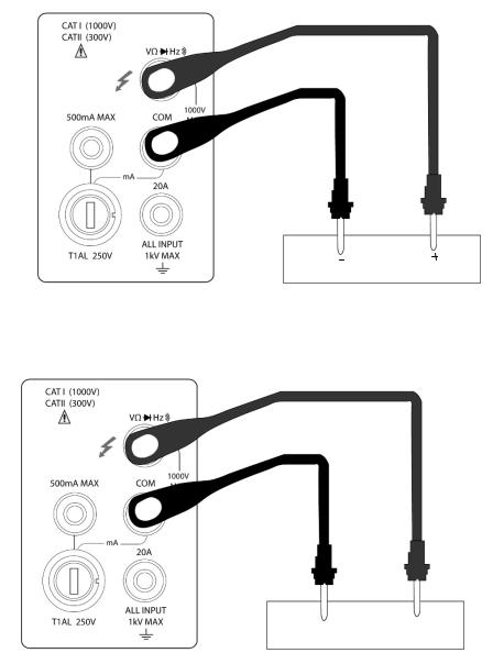
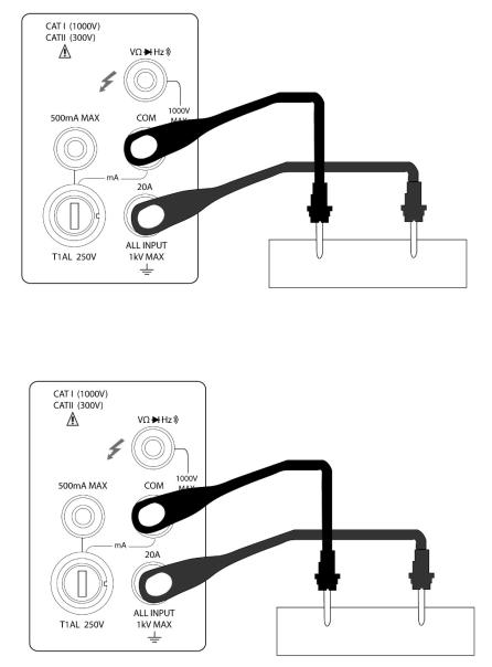
3.2.1Connections
Assuming the multimeter is under factory default conditions, the basic procedure is as follows:
1. |
Connect test leads to and COM terminals. |
2. |
Select DC or AC voltage measurement by pressing DCV or ACV . |
3.Press  to toggle between auto and manual ranging. Notice that the AUTO annunciator is displayed when in auto ranging mode. If you want manual ranging, use the RANGE
  and
and
 keys to select a measurement range consistent with expected voltage.
4.Connect test leads to the sources as shown in Figure 3-1.
CAUTION: Do not apply more than 1000V peak to the input or instrument damages may occur.
5.In manual range, if the “OVL.D” message is displayed, press the up  key to select a higher
range until a desired reading is displayed (or press  key for auto ranging). Use the lowest possible range for the best resolution.
6.Press  +
+ to turn on the secondary display, Use
  or
or  key to choose the
18
function for secondary display. 7. Take readings from the display.
DC VOLTAGE SOURCE
Input Resistance = 10 MΩ
CAUTION:Maximum Input = 1010 V peak
AC VOLTAGE SOURCE
Input Impedance = 1.1 MΩ and 100 pF
CAUTION: Maximum Input = 750 V RMS or 1000 V peak, 3x10⁷ V-Hz
Figure 3-1 DC and AC Voltage Measurement Connections
3.3Measuring Current
Model 2831E current measurement range: 2 mA, 20 mA, 200 mA, *2 A, *20 A Model 5491B current measurement range: 5 mA, 50 mA, 500 mA, *5 A, *20 A
*Indicates range is available for manual range only. Auto range will not work when reading requires
19

setting to this range.
Maximum resolution: 100nA (on 2 mA range (on 5 mA range for model 5491B))
Current measurement is available in Auto range for the lower current measurements only.
Note:
For 2831E, readings that are below 200 mA using the low current measurement input can be set in auto range. This means it will auto range between 2 mA, 20 mA, and 200 mA range. For readings above 200 mA, auto range is not available. Manual range must be used to read any readings higher than 200 mA. This means, for ranges 2 A and 20 A, only manual range is available. Additionally, the high current measurement input must be used to obtain measurements in these two higher ranges.
For 5491B, readings that are below 500 mA using the low current measurement input (fuse protected up to 500 mA max.) can be set in auto range. This means it will auto range between 5 mA, 50 mA, and 500 mA range. For readings above 500 mA, auto range is not available. Manual range must be used to read any readings higher than 500 mA. This means, for ranges 5 A and 20 A, only manual range is available. Additionally, the high current measurement input must be used to obtain measurements in these two higher ranges.
3.3.1Connections
Assuming the multimeter is under factory default conditions, the basic procedure to measure current is as follows (users must use manual range for measurement, following step 3):
1.Connect test leads between 500 mA terminal (for lower current measurements) and COM terminal or between 20 A terminal (for higher current measurements) and COM terminal.
2. Select DCI or ACI measurement function by pressing  → DCV or
  → ACV .
3.Press  toggles auto ranging. Note that auto range is only available for readings that are below 200 mA (for 2831E) and 500 mA (for 5491B) and when using the 500 mA max. terminal and COM terminal connections. For readings above these limits, only manual range is available and the 20 A terminal and COM terminal must be used to obtain measurement results. If instrument shows the AUTO annunciator on display, press again to turn off auto ranging mode and go into manual range mode. Use the RANGE
  and
and  keys to select a measurement range
consistent with expected current.
4.Connect test leads to the source as shown in Figure 3-2.
CAUTION: Do not apply more than 1 A, 250 V to the 500 mA input terminal or the fuse will be blown. For measuring current higher than 500 mA(or 200 mA for model 2831E), use the 20 A terminal instead.
5.In manual range, if the “OVL.D” message is displayed, press up  key to select a higher range until a desired reading is displayed. Use the lowest possible range for the best resolution. Press
20
 +
+ to turn on the 2nd parameter display, Use
  or
or  key to select function for
2nd display.
6. Take readings from the display.
DC CURRENT SOURCE
(Model 2831E) DC Current measurement on Range: 2 mA, 20 mA, 200 mA (Model 5491B) DC Current measurement on Range: 5 mA, 50 mA, 500 mA
AC CURRENT SOURCE
(Model 2831E) AC Current measurement on Range: 2 mA, 20 mA, 200 mA (Model 5491B) AC Current measurement on Range: 5 mA, 50 mA, 500 mA
21
DC CURRENT SOURCE
(Model 2831E) DC Current measurement on Range: 2 A, 20 A (Model 5491B) DC Current measurement on Range: 5 A, 20 A
AC CURRENT SOURCE
(Model 2831E) AC Current measurement on Range: 2 A, 20 A (Model 5491B) AC Current measurement on Range: 5 A, 20 A
CAUTION: Maximum Input = 20 A DC or RMS Maximum test times : < 20 s
Figure 3-2 DC and AC Current Measurements
3.3.2Front Panel Fuse Replacement
WARNING: Make sure the instrument is disconnected from the power line and other equipment before replacing the AMPS fuse.
1.Turn off the power and disconnect the power line and test leads.
2.From the front panel, use a screwdriver to rotate the fuse carrier several turns counter-clockwise. Take the fuse carrier out of the socket.
3.Remove the fuse and replace it with the same type (T1AL, 250V, 5×20mm .
22
CAUTION: Do not use a fuse with a higher current rating than specified or instrument may be damaged. If the instrument repeatedly blows fuses, try to find out the reason before replacing the fuse.
4. Install the new fuse by reversing the procedure above.
3.4Measuring Resistance
Model 2831E Resistance measurement range: 200 Ω, 2 kΩ, 20 kΩ, 200 kΩ, 2 MΩ, 20 MΩ; Maximum resolution: 10 mΩ (on 200 Ω range)
Model 5491B Resistance measurement range: 500 Ω, 5 kΩ, 50 kΩ, 500 kΩ, 5 MΩ, 50 MΩ; Maximum resolution: 10 mΩ (on 500 Ω range)
3.4.1Connections
Assuming the multimeter is under factory default conditions, the basic procedure for measuring resistance is as follows:
1.Connect the test leads between  and COM.
2.Select resistance measurement function by pressing 
3.Press  toggles auto ranging. Notice the AUTO annunciator is displayed with auto ranging. If you want manual ranging, use the RANGE
  and
and  keys to select a measurement range consistent with expected resistance.
4.Connect test leads to the resistance as shown in Figure 3-3:
CAUTION: Do not apply more than 1000 V peak between  and COM or instrument damage may occur.
5.In manual range, if the “OVL.D” message is displayed, press up  key to select a higher range
until a normal reading is displayed (or press  key for auto ranging). Use the lowest possible range for the best resolution.
6.Take readings from the display.
23
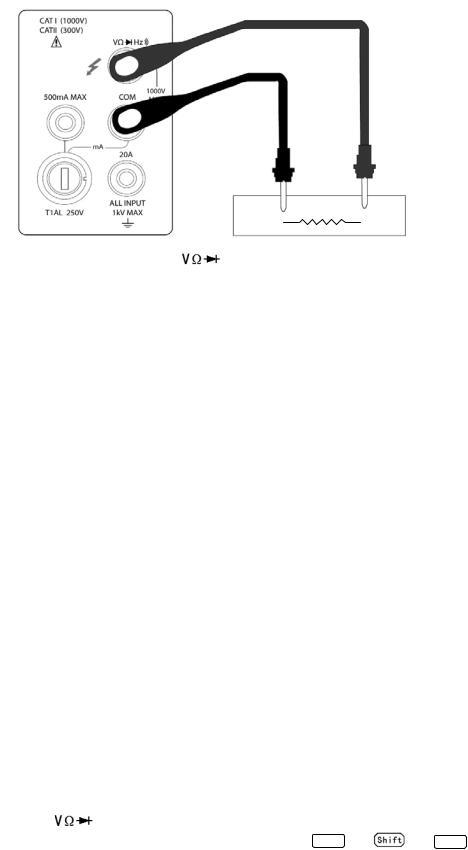
Note: |
Source current flows from the to COM terminals |
|
Figure 3-3 Resistance Measurements |
3.5Measuring Frequency and Period
Frequency measurement range: 5 Hz to more than 1 MHz.
Period measurement range: 0.2 s to less than 1 μs.
Input signal range: 200 mV AC to 750V AC.
The instrument uses the volts input terminals to measure frequency. The AC voltage range can be
changed with the RANGE  and
and  keys. However, the signal voltage must be greater than 10% of the full-scale range.
3.5.1Trigger Level and Measurement Errors
The multimeter uses a technique which maintains a constant resolution for any input frequency to measure frequency and period. The gate time is always a multiple of the measured signal period rather than a fixed time. The error will be no more than +/-1 from the total gate counts, which assures an equivalent accuracy over the whole frequency range.
3.5.2Gate Time
Gate time is the amount of time the meter uses to sample frequency or period readings. The measurement speed rate and the measuring frequency change the gate time.
3.5.3Connections
Assuming the multimeter is under factory default conditions, the basic procedure for measuring frequency and period is as follows:
1. |
Connect test leads to and COM terminals. |
2. |
Select frequency or period measurement functions by pressing FREQ or → FREQ |
3. |
Connect test leads to the source as shown in Figure 3-4: |
CAUTION: Do not exceed 1000 V peak between  and COM, or instrument may be
24
Loading...