


Instruction Manual
1
Model 1785B, 1786B, 1787B & 1788 Programmable DC Power Supplies
Content |
|
|
Quick Reference .............................................................................................................................. |
3 |
|
About your safety...................................................................................................................... |
3 |
|
|
General information........................................................................................................... |
3 |
|
Protection from electric shock ........................................................................................... |
3 |
|
Definition of users.............................................................................................................. |
3 |
Introduction ............................................................................................................................... |
4 |
|
The Front Panel at a Glance .................................................................................................... |
5 |
|
Function keys description ......................................................................................................... |
6 |
|
Menu description ...................................................................................................................... |
6 |
|
Display annunciators ................................................................................................................ |
6 |
|
The Rear Panel at a Glance ..................................................................................................... |
7 |
|
Chapter 1 Quick Start ...................................................................................................................... |
8 |
|
1.1 |
Preliminary Checkout ......................................................................................................... |
8 |
1.2 |
Output Checkout................................................................................................................. |
9 |
|
1.2.1 Voltage Output Checkout ......................................................................................... |
9 |
|
1.2.2 Current Output Checkout ......................................................................................... |
9 |
1.3 |
If the Power Supply Does Not Turn On ............................................................................ |
10 |
1.4 |
To Adjust the Carrying Handle ......................................................................................... |
10 |
1.5 |
To Rack Mount the Instrument ......................................................................................... |
11 |
Chapter 2 Specifications ................................................................................................................ |
12 |
|
2.1 |
Specifications.................................................................................................................... |
12 |
2.2 |
Supplemental Characteristics........................................................................................... |
13 |
Chapter 3 Front-panel Operation................................................................................................... |
15 |
|
3.1 |
Front-panel Operation Overview ...................................................................................... |
15 |
3.2 |
Constant Voltage Operation ............................................................................................. |
15 |
3.3 |
Constant Current Operation ............................................................................................. |
16 |
3.4 |
Saving and Recalling Operation ....................................................................................... |
16 |
3.5 |
Menu Operation ................................................................................................................ |
16 |
Chapter 4 Remote Operation Mode............................................................................................... |
19 |
|
4.1 |
Communication setting ..................................................................................................... |
19 |
4.2 |
DB9 interface details......................................................................................................... |
19 |
4.3 |
Frame format .................................................................................................................... |
20 |
4.4 |
Communication protocol................................................................................................... |
20 |
Chapter 5 Calibration ..................................................................................................................... |
27 |
|
|
5.1 Configuration ............................................................................................................. |
28 |
5.2 |
Voltage calibration ............................................................................................................ |
28 |
5.3 |
Current calibration ............................................................................................................ |
28 |
5.4 |
Reset to the default calibration settings ........................................................................... |
29 |
Chapter 6 PV1785B_1788 Software.............................................................................................. |
29 |
|
6.1 |
Introduction ....................................................................................................................... |
29 |
6.2 |
System installation............................................................................................................ |
29 |
6.3 |
PV1785B_1788 Functions................................................................................................ |
30 |
|
6.3.1Configure the system .............................................................................................. |
31 |
|
6.3.2 Status bar ............................................................................................................... |
31 |
|
6.3.3 Setting Voltage and current.................................................................................... |
32 |
|
6.3.4. GO/NG Test Function ............................................................................................ |
33 |
|
6.3.5 Save and Open ...................................................................................................... |
34 |
|
6.3.6 Present Voltage/Current Chart ............................................................................... |
34 |
|
6.3.7. Chart Description................................................................................................... |
34 |
Certification and Warranty ........................................................................................................ |
4 |
|
|
Certification.......................................................................................................................... |
|
|
Warranty .............................................................................................................................. |
|
|
Limitation of Warranty ......................................................................................................... |
|
2
Quick Reference
About your safety
Pease review the following safety precautions before operating our equipment.
General information
The following safety precautions should be observed before using this product and any associated instrumentations. Although some instruments and accessories would be used with non-hazardous voltages, there are situations where hazardous conditions may be present.
This product is intended for use by qualified personnel who recognize shock hazards and are familiar with the safety precautions required to avoid possible injury. Read and follow all installation, operation, and maintenance information carefully before using the product. Refer to this manual for complete product specifications.
If the product is used in a manner not specified, the protection provided by the product may be impaired.
Before performing any maintenance, disconnect the line cord and all test cables.
Protection from electric shock
Operators of this instrument must be protected from electric shock at all times. The responsible body must ensure that operators are prevented access and/or insulated from every connection point. In some cases, connections must be exposed to potential human contact. Product operators in these circumstances must be trained to protect themselves from the risk of electric shock. If the circuit is capable of operating at or above 1000 volts, no conductive part of the circuit may be exposed.
Definition of users
Responsible body is the individual or group responsible for the use and maintenance of equipment is operated within its specifications and operating limits, and for ensuring that operators are adequately trained.
Operators use the product for its intended function. They must be trained in electrical safety procedures and proper use of the instrument. They must be protected from electric shock and contact with hazardous live circuits.
Service is only to be performed by qualified service personnel. Safety symbols and terms
Connect it to safety earth ground using the wire recommended in the user manual.
The symbol on an instrument indicates that the user should refer to the operating instructions located in the manual.
High voltage danger
3
Certification and Warranty
Certification
We certify that this product met its published specifications at time of shipment from the factory.
Introduction
The 1785B - 1788 Series power supplies are high performance single-output programmable DC power supplies with communication interface. The combination of bench-top and system features in these power supplies provides versatile solutions for your design and test requirements.
Convenient bench-top features:
•Nice appearance, small-size and light weight
•VFD display
•Soft Rubber numeric keypad
•Adjustable & constant voltage outputs
•Adjustable & constant current outputs
•Output on/off
•High accuracy and high resolution
•Excellent load and line regulation
•Low ripple and noise
•Limit voltage protection
•Over current/temperature protection
•Sixteen operating states storage
•May be used in series or parallel modes with additional power supplies
4
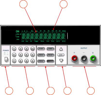
The Front Panel at a Glance
1 |
2 |
3 |
4 |
5 |
6 |
7 |
?10 digits VFD display
?Status information for operating mode and working status
?Power switch
?Number keys
?Function keys
?UP/DOWN and ENTER key
?Output terminals
5
Function keys description
V-set |
Set the output voltage value |
|
|
I-set |
Set the current value |
|
Save the present settings to a specified register location(1~16)
Save
Recall a saved settings from location ‘‘1’’through ‘‘16’
Recall
Menu function to set related parameters of the power supply
Menu
Output ON/OFF, to enable/disable the output
Out on/off
Menu description
Menu |
|
|
|
|
|
|
>MAX VOLT |
Set the maximum output voltage value |
|
>INIT OUT |
Initiate the output state to ON or not |
|
>INIT VOL |
Initiate the output voltage to 0 volt or not |
|
>KEY SOUN |
Switch On/Off the buzzer sound when you press |
|
|
any key |
|
>BAUDRATE |
Set the communication baud rate |
|
>ADDRESS |
Set the communication address |
|
>KEY LOCK |
Set the password for function keys |
|
>EXIT |
Exit |
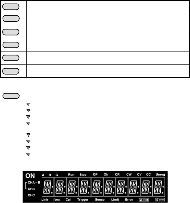
Display annunciators
6

ON |
Output ON |
Link The power supply is in communication |
|
Oh |
Overheat protection state |
|
mode |
CV The power supply is in constant |
Rmt The power supply is in remote mode |
||
|
voltage mode. |
Cal |
The power supply is in calibration mode |
CC The power supply is in constant |
|
The function keys are locked by password |
|
|
current mode. |
|
|
|
|
|
|
Unreg The output of the power supply |
|
The rotate speed of cooling fan |
|
|
is unregulated (neither CV nor CC) |
|
|
|
|
|
|
|
|
|
|
The Rear Panel at a Glance
1 |
2 |
3 |
4 |
5 |
?Cooling window
?DB9 interface connector
?110V/220V selector
?Fuse
?Power socket
7
Chapter 1 Quick Start
One of the first things you will want to do with your power supply is to become acquainted with the front panel. The exercises in this chapter prepare the power supply for use and help you get familiar with some of its front-panel operations.
This chapter is intended for both the experienced and the inexperienced user because it calls attention to certain checks that should be made prior to operation.
1.1 Preliminary Checkout
The following steps help you verify that the power supply is ready for use.
1. Check the list of supplied items.
Verify that you have received the following items with your power supply. If anything is missing, contact your nearest Sales Office.
?One power cord for your location
?This User’s Manual.
?Communication cable (optional)
2. Connect the power cord and turn on the power supply.
When you turn on the power supply, the front-panel display will light up briefly while the power supply performs its power-on self-test. All the VFD annunciators will light up at once. To review the display with all annunciators, you can check if there is any stroke loss on any annunciator. If there isn’t any response when you power on the power supply, please see Section 1.5 on page 10 for some service information.
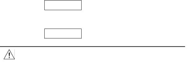
If the EEPROM was damaged or the latest operation data in EEPROM was lost, the VFD will display as follows:
ERR EEPROM
If the calibration data in EEPROM was lost, the VFD will display as follows:
ERROR CAL
Warning: Your power supply is equipped with a 3-wire grounding type power cord; the third conductor being the ground. The power supply is grounded only when the power-line cord is plugged into an appropriate receptacle. Do not operate your power supply without adequate cabinet ground connection.
8
1.2 Output Checkout
The following procedures check to ensure that the power supply develops its rated outputs and properly responds to operation from the front panel.
1.2.1 Voltage Output Checkout
The following steps verify basic voltage functions without load.
1.Turn on the power supply.
2.Enable the outputs.
Press Out on/off key to let the ON annunciator and the CV annunciator turn on to light.
Notice: if the voltage value flash, then the power supply is in Set mode, ‘‘Set mode’’ means that the VFD display shows the setting output voltage and current. Or the power supply is in Meter mode, ‘Meter mode” means that the VFD display shows the actual output voltage and current.
3. Check that the front-panel voltmeter properly responds to number keys
Set some different voltage values, then wait till the Meter mode to check if the VFD displayed voltage value is the same as the set voltage value, and to check if the VFD displayed current value is nearly zero.
4. Ensure that the voltage can be adjusted from zero to the full rated value.
1.2.2 Current Output Checkout
The following steps check basic current functions with a short across the power supply’s output.
1.Turn on the power supply.
2.Disable the output
Press Out on/off key to ensure that the output is disabled. The ON annunciator is turned off. |
3. Connect a short across (+) and (-) output terminals with an insulated test lead.
Use a wire size sufficient to handle the maximum current.
Warning: To satisfy safety requirements, load wires must be heavy enough not to overheat when carrying the maximum short-circuit output current of the power supply. If there is more than one load, then any pair of load wires must be capable of safety carrying the full-rated current of the power supply.
4. Enable the output.
Press key to ensure that the output is enabled. The ON annunciator is turned on.
5.Adjust the voltage value to 1.0 volt.
Adjust the voltage to 1.0 volt to ensure the power supply is in CC operation mode. The CC annunciator will turn on.
6.Adjust the current value.
Set some different voltage values, then wait till the Meter mode to check if the VFD displayed current value is the same as the set voltage value, and to check if the VFD displayed voltage value is nearly
9
zero.
7.Ensure that the current can be adjusted from zero to the full rated value.
8.Turn off the power supply and remove the short wire from the output terminals.
1.3 If the Power Supply Does Not Turn On
Use the following steps to help solve problems you might encounter when turning on the instrument. If you need more help, refer to chapter 6 for instructions on returning the instrument to the supplier for service.
1. Verify that there is AC power to the power supply.
First, verify that the power cord is firmly plugged into the power receptacle on the rear panel of the power supply. You should also make sure that the power source you plugged the power supply into is energized. Then, verify that the power supply is turned on.
2. Verify the power-line voltage setting.
The line voltage is set to the proper value for your country (110VAC or 220VAC. Change the voltage setting if it’s not correct.
3. Verify that the correct power-line fuse is installed.
If the fuse was damaged, please see the table below to replace the fuse for your power supply.
Fuse Description
Fuse 2.5A T 250V for 220VAC
Fuse 5A T 250V for 110VAC
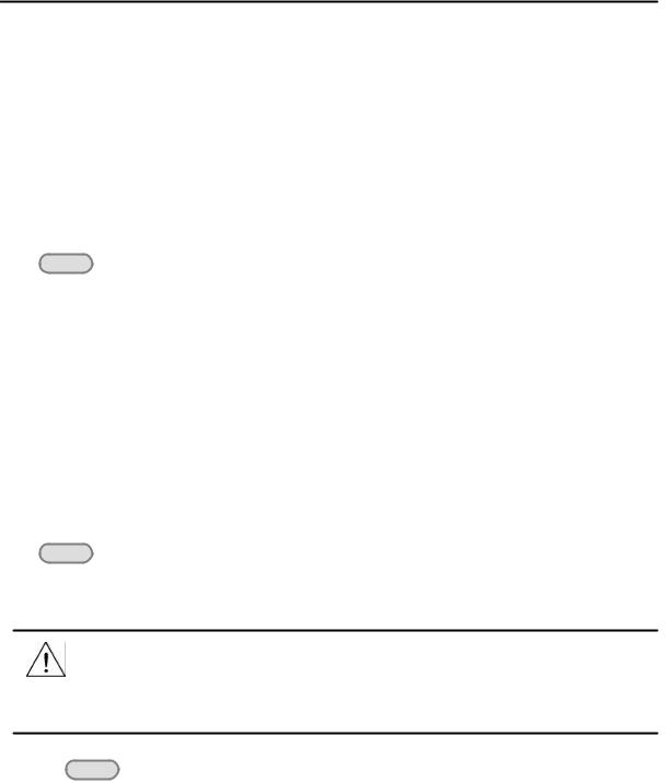
1.4 To Adjust the Carrying Handle
To adjust the position, grasp the handle by the sides and pull outward. Then, rotate the handle to the desired position.
10

Bench-top viewing positions |
Carrying position |
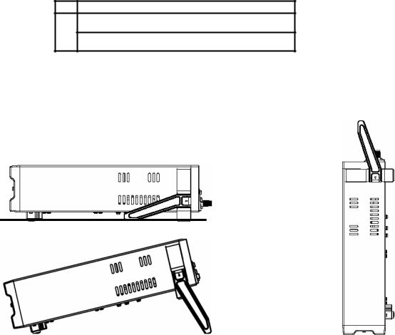
1.5 To Rack Mount the Instrument
You can mount the power supply in a standard 19-inch rack cabinet using the IT-E151 rack mount kit.
Note: Remove the carrying handle and the two plastic ears before rack-mounting the instrument.
To remove the handle, grasp the handle by sides and pull outwards and rotate it to a special position to let the arrow on the handle and the arrow on the plastic ears be in opposite directions, then pull the handle outward. After removing the handle, you can use a screwdriver to remove the two plastic ears.
To rack mount a single instrument, order rack mount kit IT-E151
Side view of rack mounting a single instrument
11
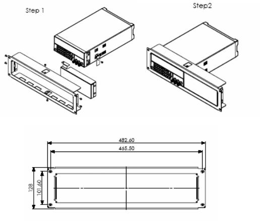
To rack mount two instruments side-by-side, order rack mount kit IT-E151, you needn’t to use the front cover panel.
Dimension |
unit (mm) |
Chapter 2 Specifications
2.1 Specifications
Parameter |
|
|
1785B |
|
|
1786B |
|
1787B |
|
1788 |
||
Output Ratings, |
Voltage |
|
0 ~18V |
|
|
0 ~32V |
|
0 ~72V |
|
0 ~32V |
||
Current |
|
0 ~5A |
|
|
0 ~3A |
|
0~1.5A |
|
0~6A |
|||
( 0 °C - 40 °C) |
|
|
|
|
|
|||||||
|
LVP |
|
0 ~19V |
|
|
0 ~33V |
|
0 ~73V |
|
0 ~33V |
||
|
|
|
|
|
|
|
|
|
|
|
|
|
Load Regulation, |
Voltage |
|
|
|
|
|
<0.01% + 3mV |
|
||||
|
Model 1788 = <0.02% + 5mV |
|||||||||||
|
|
|||||||||||
±(% of output+offset) |
|
|
|
|
|
|
|
|
|
|
|
|
Current |
|
|
|
|
|
<0.1% + 2mA |
|
|||||
|
|
|
|
|
|
|
||||||
|
|
|
|
|
|
|
|
|
|
|||
Line Regulation, |
Voltage |
|
|
|
|
|
<0.1% + 3mV |
|
||||
|
|
|
|
|
|
|
|
|
|
|
|
|
±(% of output+offset) |
Current |
|
|
|
|
|
<0.1% + 2mA |
|
||||
|
|
|
|
|
|
|
||||||
|
|
|
|
|
|
|
|
|
|
|||
Programming |
Voltage |
|
|
|
|
|
|
10mV |
|
|||
|
|
|
|
|
|
|
|
|
|
|
|
|
Resolution |
Current |
|
|
|
|
|
|
10mA |
|
|||
|
|
|
|
|
|
|
|
|||||
|
|
|
|
|
|
|
|
|
||||
|
|
|
|
|
|
|
|
|||||
|
Voltage |
|
|
0.05% + 15mV(<20V) |
|
|||||||
Readback Resolution |
|
Model 1788 = 0.05% + 120mV(=20V) |
||||||||||
|
|
|||||||||||
Current |
|
|
|
|
|
< 0.1% + 15mA |
|
|||||
|
|
|
|
|
|
|
||||||
|
|
|
|
|
|
|
|
|
|
|
|
|
12
 Loading...