


INSTRUCTION |
|
MANUAL |
4080 Series |
|
Function and Arbitrary/Function Generators
Model 4084AWG, 4086AWG, 4084, 4085, 4086, 4087

4080 series Arbitrary/Function Generator with Counter –Instruction Manual
Safety Summary
The following safety precautions apply to both operating and maintenance personnel and must be observed during all phases of operation, service, and repair of this instrument. Before applying power, follow the installation instructions and become familiar with the operating instructions for this instrument.
Failure to comply with these precautions or with specific warnings elsewhere in this manual violates safety standards of design, manufacture, and intended use of the instrument. B&K Precision Corporation assumes no liability for a customer’s failure to comply with these requirements. This is a Safety Class I instrument.
GROUND THE INSTRUMENT
To minimize shock hazard, the instrument chassis and cabinet must be connected to an electrical ground. This instrument is grounded through the ground conductor of the supplied, three-conductor ac power cable. The power cable must be plugged into an approved three-conductor electrical outlet. Do not alter the ground connection. Without the protective ground connection, all accessible conductive parts (including control knobs) can render an electric shock. The power jack and mating plug of the power cable meet IEC safety standards.
DO NOT OPERATE IN AN EXPLOSIVE ATMOSPHERE
Do not operate the instrument in the presence of flammable gases or fumes. Operation of any electrical instrument in such an environment constitutes a definite safety hazard.
KEEP AWAY FROM LIVE CIRCUITS
Instrument covers must not be removed by operating personnel. Component replacement and internal adjustments must be made by qualified maintenance personnel. Disconnect the power cord before removing the instrument covers and replacing components. Under certain conditions, even with the power cable removed, dangerous voltages may exist. To avoid injuries, always disconnect power and discharge circuits before touching them.
WARNINGS AND CAUTIONS
WARNING and CAUTION statements denote a hazard. Follow all instructions contained in these statements.
A WARNING statement calls attention to an operating procedure, practice, or condition, which, if not followed correctly, could result in injury or death to personnel.
A CAUTION statement calls attention to an operating procedure, practice, or condition, which, if not followed correctly, could result in damage to or destruction of part or all of the product.
WARNING: |
Do not alter the ground connection. Without the protective ground |
|
connection, all accessible conductive parts (including control knobs) can |
|
render an electric shock. The power jack and mating plug of the power |
|
cable meet IEC safety standards. |
WARNING: |
To avoid electrical shock hazard, disconnect power cord before removing |
|
covers. Refer servicing to qualified personnel. |
CAUTION: |
Before connecting the line cord to the AC mains, check the rear panel AC |
|
line voltage indicator. Applying a line voltage other than the indicated |
|
voltage can destroy the AC line fuses. For continued fire protection, replace |
|
fuses only with those of the specified voltage and current ratings. |
2

|
4080 series Arbitrary/Function Generator with Counter –Instruction Manual |
|
|
Table of Contents |
|
1. PRODUCT INTRODUCTION................................................................................................ |
5 |
|
1.1 |
Description ....................................................................................................................... |
5 |
1.2 |
Key features...................................................................................................................... |
5 |
2. SPECIFICATIONS .................................................................................................................. |
6 |
|
2.1 |
Function Generator........................................................................................................... |
6 |
2.2 |
Universal Counter............................................................................................................. |
9 |
2.3 |
General ............................................................................................................................. |
10 |
3. PANEL DESCRIPTION .......................................................................................................... |
11 |
|
3.1 |
Front Panel........................................................................................................................ |
11 |
|
3.1.1 Overview of Keys .................................................................................................... |
11 |
|
3.1.2 Display Annunciators............................................................................................... |
12 |
|
3.1.3 Description of front panel keys ................................................................................ |
13 |
|
3.1.3 Description of menu parameters .............................................................................. |
14 |
3.2 |
Rear Panel......................................................................................................................... |
17 |
4. OPERATING INSTRUCTIONS.............................................................................................. |
18 |
|
4.1 |
Installation ........................................................................................................................ |
18 |
4.2 |
Main operating modes ...................................................................................................... |
18 |
4.3 Waveform Selection.......................................................................................................... |
19 |
|
4.4 |
Data entry ......................................................................................................................... |
20 |
4.5 |
Output Configuration........................................................................................................ |
21 |
|
4.5.1 Set Frequency and Period......................................................................................... |
21 |
|
4.5.2 Set Amplitude........................................................................................................... |
21 |
|
4.5.3 Set DC Offset Voltage .............................................................................................. |
22 |
|
4.5.4 Adjust duty cycle...................................................................................................... |
22 |
|
4.5.5 Sync/TTL Signal ...................................................................................................... |
23 |
|
4.5.6 Signal Store and Recall ............................................................................................ |
23 |
4.6 |
Set Modulation and Sweep Parameters ............................................................................ |
24 |
|
4.6.1. Sweep mode ............................................................................................................ |
24 |
|
4.6.2 FM modulation......................................................................................................... |
26 |
|
4.6.3 AM modulation ........................................................................................................ |
27 |
|
4.6.4 Burst modulation...................................................................................................... |
28 |
|
4.6.5 FSK modulation ....................................................................................................... |
30 |
|
4.6.6 PSK modulation ....................................................................................................... |
31 |
4.7 |
Set System Parameters...................................................................................................... |
32 |
4.8 |
Universal Counter............................................................................................................. |
34 |
5. REMOTE INTERFACE REFERENCE................................................................................... |
35 |
|
5.1 |
Introduction ...................................................................................................................... |
35 |
5.2 |
Overview and syntax of SCPI instructions....................................................................... |
35 |
5.3 |
Detailed description of SCPI Instructions ........................................................................ |
39 |
6. USER PROGRAMMABLE ARBITRARY WAVEFORM MODULE .................................... |
47 |
|
7. APPENDIX .............................................................................................................................. |
57 |
|
A) Declaration of conformity ................................................................................................. |
58 |
|
B) Service and Warranty Information..................................................................................... |
57 |
|
3

4080 series Arbitrary/Function Generator with Counter –Instruction Manual
Intentionally left blank
4

4080 series Arbitrary/Function Generator with Counter –Instruction Manual
1. PRODUCT INTRODUCTION
1.1 Description
The B+K Precision 4080 Series are laboratory grade synthesized function generators with a wide frequency range of up to 120 MHz. Direct digital synthesis (DDS) techniques are used to create stable, accurate output signals for clean, low distortion sine waves and an extensive selection of built-in standard and arbitrary waveforms. The instrument supports AM, FM, FSK, PSK and pulse modulation and linear and logarithmic sweep. Modulation parameters can be set precisely and are adjustable over a wide range. The 4080 Series supports internal and external modulation sources as well as internal, external and gated trigger sources.
All models are capable of generating complex, predefined arbitrary waveforms. Additionally, models 4084AWG and 4086AWG provide the flexibility to create custom waveforms. The AWG module includes an intuitive, graphical Windows based software tool for creating and editing custom arbitrary waveforms and transferring the waveforms to the instrument’s non-volatile memory. The software also provides a direct interface to Tektronix® TDS1000, TDS2000 TPS2000 and TDS3000 series digital storage oscilloscopes offering users a convenient means to recreate waveforms originating from the DSO’s display or internal memory.
The 4080 Series front-panel operation is straightforward. Parameters can be entered using the knob or directly via the numerical keypad and unit keys.
The instruments are fully programmable via the standard RS232 interface. The command set is SCPI (standard Commands for Programmable Instruments) compatible.
The combination of classical function and arbitrary waveform generator makes this series a versatile solution for many applications in Electronic Test and Design, Sensor Simulation, Education and Training.
1.2Features
•Direct Digital Synthesis (DDS) architecture
•Wide frequency range of 1µHz ~ 120MHz (model 4087, sine wave only)
•Clean and stable output of very small signals down to 1mV (50Ω)
•27 build-in standard and complex waveforms.
•Eight downloadable 16000 point memories for custom arbitrary waveforms (models 4084AWG and 4086AWG only)
•Graphical Arbitrary Waveform Generation Software tool for Microsoft® WindowsTM (models 4084AWG and 4086AWG only)
•Convenient data input via knob or numerical keypad.
•Bright, easy to read display using VFD (Visible Vacuum Fluorescent) technology
•Fully programmable via SCPI compatible command set
•100 MHz Universal Counter with frequency measurement and totalize function
5

4080 series Arbitrary/Function Generator with Counter –Instruction Manual
2. SPECIFICATIONS
2.1 Function Generator
Waveform Characteristics
Main Waveforms: Sine, square
Waveform Amplitude resolution: 12 bits
Sample Rate: |
200MSa/s (4084, 4084AWG, 4085, 4086, 4086AWG) |
|
300MSa/s (4087) |
Sine:
Harmonic Distortion of Sine Wave:
≤- 50dBc (frequency ≤ 5MHz)
≤- 45dBc (frequency ≤ 10MHz)
≤- 40dBc (frequency ≤ 20MHz)
≤- 35dBc (frequency ≤ 40MHz)
≤- 30dBc (frequency > 40MHz)
Total Harmonic distortion: 0.1% (20Hz ~ 100kHz) Square:
Rise and Fall Time of Square Wave: ≤15ns
Note: Test conditions for harmonic distortion, sine distortion, rise/fall time: Output Amplitude 2Vp-p, Environmental temperature: 25 ±5
Build in standard and complex (arbitrary) waveforms: 27 build-in standard and complex waveforms.
Sine, Square, Triangle, Positive Ramp, Falling Ramp, Noise, Positive Pulse, Negative Pulse, Positive DC, Negative DC, Stair wave, Coded Pulse, Full wave rectified, Half-wave rectified, Sine transverse cut, Sine vertical cut, Sine phase modulation, Logarithmic, Exponential, Half-round, SINX/X, Square root, Tangent, Cardiac, Earthquake, Combination
Waveform Length: 4096 dots Amplitude Resolution: 10 bits
Pulse Wave:
Duty Cycle: 0.1% ~ 99.9% (below 10kHz), 1% ~ 99% (10kHz ~ 100kHz) Rise/Fall Time: ≤100ns Duty cycle 20%
DC signal characteristics:
DC range: ≤ 10mV – 10V (high impedance)
DC Accuracy: ≤ ±5% of setting +10mV (high impedance)
Module for user defined arbitrary waveform generation (models 4084AWG and 4086AWG only) Number of memory locations for arbitrary waveforms: 8
Length of waveforms 8~16000 points Resolution of waveform amplitude 10 bits Frequency range 100µHz~100kHz Sample rate 200MSa/s
6

4080 series Arbitrary/Function Generator with Counter –Instruction Manual
Frequency Characteristics
Frequency Range:
Main waveforms (sine, square):
Model 4084/4084AWG: 1µHz ~ 20MHz
Model 4085: |
1µHz ~ 40MHz |
Model 4086/4086AWG 1µHz ~ 80MHz (sine wave) |
|
|
1µHz ~ 40MHz (square wave) |
Model 4087 |
1µHz ~ 120MHz (sine wave) |
|
1µHz ~ 40MHz (square wave) |
All other waveforms: |
|
All models: |
1µHz ~ 100kHz |
Frequency Stability: |
±1×10⁻⁶ (22 ±5 |
Resolution: |
1µHz |
Frequency Accuracy: |
≤ ± 5×10⁻⁶ (22 ±5 |
Data entry Units: |
s, ms, Hz, kHz, MHz |
Amplitude Characteristics
Amplitude Range:
4084, 4084AWG: 2mV ~ 20Vpp (open circuit), 1mV ~ 10Vpp (50Ω)
4085
4086, 4086AWG: |
for Freq ≤ 40MHz: 2mV ~ 20Vpp (open circuit), 1mV ~ 10Vpp (50Ω) |
|
|
|
for Freq > 40MHz: 2mV ~ 4Vp-p (open circuit), 1mV ~ 2Vpp (50Ω) |
4087: |
for Freq ≤ 40MHz: 2mV ~ 20Vpp (open circuit), 1mV ~ 10Vpp (50Ω) |
|
|
for Freq > 40MHz: -76dBm ~ +13.5 dBm 50Ω or 0.1mV ~ 3Vpp 50Ω |
|
Max. Resolution: |
|
2µVpp (open circuit), 1µVpp (50Ω) |
Amplitude Accuracy: |
± 1%+0.2mV (sine wave relative to 1kHz) |
|
Amplitude Stability: |
±0.5 % /3 hours |
|
||
Flatness: |
|
|
|
|
For amplitude ≤ 2Vpp: |
±3% (frequency≤5MHz), |
±10% (5MHz<frequency≤40MHz) |
||
For amplitude >2Vpp: |
±5% (frequency≤5MHz), |
±10% (5MHz<frequency≤20MHz) |
||
|
|
|
|
±20% (frequency>20MHz) |
Models 4086/AWG, 4087 only: ±1dBm (frequency>40MHz) |
||||
Output Impedance: 50Ω |
|
|
|
|
Output Units: |
Vpp, mVpp, Vrms, mVrms, dBm |
|
||
7

4080 series Arbitrary/Function Generator with Counter –Instruction Manual
DC Offset Characteristics |
|
Offset Range (open circuit) |
|
Freq ≤ 40MHz): ±10Vpk ac + dc |
(Offset ≤ 2×peak-to peak amplitude) |
Freq > 40MHz): ±2Vpk ac + dc |
(Offset ≤ 2×peak-to peak amplitude) |
Resolution: 2µV (open circuit), 1µV (50Ω)
Offset Error: ±5% of setting +10mV (Ampl. ≤ 2Vpp into open circuit) ±5% of setting +20mV (Ampl. > 2Vpp into open circuit)
AM Characteristics |
|
|
|
|
Carrier Waveforms: |
|
sine or square |
|
|
Carrier Frequency Range: |
same as main waveforms |
|||
Modulation Source |
|
internal or external |
|
|
Modulating Waveform: |
|
5 internal waveforms (sine, square, triangle, rising/falling ramp) |
||
Frequency of modulating signal: 100µHz ~ 20kHz |
||||
Distortion: |
|
≤ 2% |
|
|
Modulation Depth: |
|
1% ~ 120% |
|
|
|
|
1% ~ 80% (frequency>40MHz, Ampl > 2Vpp into open circuit) |
||
Modulation Error: |
|
± 5%+0.2% |
(100µHz < frequency ≤ 10kHz) |
|
|
|
±10%+2% |
(10kHz < frequency ≤ 20kHz) |
|
Amplitude of ext. input signal: |
3Vp-p (-1.5V~ +1.5V) |
|||
FM Characteristics |
|
|
|
|
Carrier Waveforms |
|
sine or square |
|
|
Carrier Frequency Range: |
same as main waveforms |
|||
Modulation Source: |
|
internal or external |
|
|
Modulating Waveform: |
|
5 internal waveforms (sine, square, triangle, rising/falling ramp) |
||
Frequency of modulating signal: 100µHz ~ 10kHz |
||||
Peak Frequency Deviation: |
|
Max. 50% of carrier frequency for internal FM |
||
|
|
|
Max 100kHz (carrier frequency≥5MHz) for external FM, |
|
|
|
|
with input signal voltage 3Vp-p (-1.5V~+1.5V) |
|
FSK Characteristics |
|
|
|
|
Carrier Waveform |
|
sine or square |
|
|
Carrier Frequency Range: |
same as main waveforms |
|||
Control Mode |
|
internal or external trigger (external: TTL level, low level F1, |
||
|
|
high level F2) |
|
|
FSK Rate: |
|
0.1ms ~ 800s |
|
|
PSK Characteristics |
|
|
|
|
Waveform: |
sine or square |
|
||
Frequency Range: |
same as main waveforms |
|||
PSK: |
Phase 1 (P1) and Phase 2 (P2), range: 0.0 ~ 360.0° |
|||
Resolution: |
0.1° |
|
|
|
PSK rate: |
0.1ms ~ 800s |
|
||
8

4080 series Arbitrary/Function Generator with Counter –Instruction Manual
Control Mode: |
internal or external trigger (external: TTL level, low level P1, |
|
|
high level P2) |
|
Burst Characteristics |
|
|
Waveform: |
sine or square |
|
Frequency Range: |
same as main waveforms |
|
Burst Counts : |
1 ~ 10000 cycles |
|
Time interval between bursts: |
0.1ms ~ 800s |
|
Control Mode: |
internal, single or external gated trigger |
|
Frequency Sweep Characteristics |
||
Waveform: |
sine or square |
|
Start/Stop Freq.: |
same as main waveforms |
|
Sweep Time: |
1ms ~ 800s (linear), 100ms ~ 800s (log) |
|
Sweep Mode: |
Linear or Logarithmic |
|
External trigger signal frequency: DC ~ 1kHz (linear) DC~10Hz (log) |
||
Control Mode: |
internal or external trigger |
|
Rear Panel Terminals (for modulation and sweep)
Output MOD OUT |
|
Frequency: |
100µHz ~ 20kHz |
Waveform: |
sine, square, triangle, rising/falling ramp |
Amplitude: |
5Vp-p ± 5% |
Output Impedance: 600Ω
Modulation IN
3 Vpp = 100% Modulation
External Input Trig/FSK/Burst
Level: TTL
Main OUTput |
|
Impedance: |
50Ω |
Protection: |
Short circuit and overload protected |
State Storage Characteristics |
|
Storage Parameters: |
frequency, amplitude, waveform, DC offset values, modulation |
|
parameters |
Storage Capacity: |
10 user configurable stored states |
Storage Time: |
more than 10 years |
2.2 Universal Counter
Frequency Range |
|
Frequency Measurement: |
1Hz ~ 100MHz |
Totalize mode: |
50MHz max |
9

4080 series Arbitrary/Function Generator with Counter –Instruction Manual
Input Characteristics |
|
|
Sensitivity |
|
|
Input attenuator disabled: |
50mVrms (f: 10Hz ~ 50MHz), 100mVrms (f: 1Hz ~ 100MHz) |
|
Input attenuator enabled: |
0.5Vrms (f: 10Hz ~ 50MHz), 1Vrms (f: 1Hz ~ 100MHz) |
|
Max. Input Voltage Allowed: |
100Vp-p (f≤100kHz), 20Vp-p (1Hz~100MHz) |
|
Input Impedance: |
|
R>500kΩ, C<30pF |
Coupling: |
AC |
|
Waveform: |
sine or square |
|
Low Pass Filter: |
cut off frequency about 100kHz (with internal attenuation: ≤ -3dB) |
|
|
with external attenuation: ≥ -30 dB (f >1MHz) |
|
Gate Time Setting: |
10ms ~ 10s continuously adjustable |
|
Display Bits: |
8 (for gate Time>5s) |
|
Totalize Capacity: |
≤ 4.29×10⁹ |
|
Control Mode: |
manual or external gate control |
|
Accuracy: |
time base error ± trigger error (when signal SNR > 40dB, |
|
|
trigger error ≤ 0.3) |
|
Time base: |
|
|
Type: |
small TCXO |
|
Frequency: |
10MHz |
|
Stability: |
±1 × 10⁻⁶ (22°C±5°C) |
|
2.3 General
Power Supply
Power Consumption:
Operating Temperature
Operating Humidity
Storage Temperature
Dimensions (W x H x D):
Weight:
Remote Interface
Accessories included BNC to alligator cable BNC to BNC cable
RS232 communication cable Power line cord
Test report Spare fuse
Installation disk for Arbitrary
198~242V or 99~121V, Frequency: 47~ 63Hz <35VA
0° to +40 °C
80% R.H -40 to 70
255 mm x 100 mm x 370 mm (10.0 x 3.93 x 14.56 inch)
3 kg (6.6 lbs): models 4084, 4084AWG, 4085, 4086, 4086AWG 3.5 kg (7.7 lbs) model 4087
RS232
Waveform Creation Software (models 4084AWG or 4086AWG only)
NOTE: Specifications and information are subject to change without notice. Please visit www.bkprecision.com for the most current product information.
10

4080 series Arbitrary/Function Generator with Counter –Instruction Manual
3. PANEL DESCRIPTION
3.1 Front Panel
3.1.1 Overview of Keys:
Summary: Most keys have multiple functions. Primary functions are written on the key. Simply press the respective key to enable a primary functions. All Function/Mode keys and some of the numerical entry keys have associated secondary functions indicated above each key in blue. To activate a secondary function, press the shift key followed by the desired key. The bottom row of the Function/Mode keys can be used to enter units directly. The unit is indicated below each key. To enter a unit, enter a numerical value via the numerical keypad then press the corresponding unit key. The unit key also serves as Enter function.
Data entry keys: |
|
||
Key |
Main |
Secondary |
|
Name |
Function |
Function |
|
0 |
Input Digit 0 |
Enter SW mode |
|
1 |
Input Digit 1 |
Enable ARB1 |
|
waveform *** |
|||
|
|
||
2 |
Input Digit 2 |
Enable ARB2 |
|
waveform *** |
|||
|
|
||
3 |
Input Digit 3 |
Enable ARB3 |
|
wave *** |
|||
|
|
||
4 |
Input Digit 4 |
Enable ARB4 |
|
waveform*** |
|||
|
|
||
5 |
Input Digit 5 |
Enable ARB5 |
|
waveform *** |
|||
|
|
||
6 |
Input Digit 6 |
Enable ARB6 |
|
waveform*** |
|||
|
|
||
Key |
Main function |
Secondary |
|
Name |
Function |
||
|
|||
7 |
Input Digit 7 |
Enable ARB7 |
|
waveform ***. |
|||
|
|
||
8 |
Input Digit 8 |
Enable ARB8 |
|
waveform *** |
|||
|
|
||
9 |
Input Digit 9 |
Not available |
●Input decimal point Reset Unit
▬ |
Input negative |
Enter system menu |
|
symbol |
|||
|
|
||
◄ |
Move arrow key to |
Select pulse |
|
left * |
|||
|
|
||
► |
Move arrow key to |
Select Arblist |
|
right ** |
waveform |
||
|
*: Direct number entry: Press this key to clear the least significant bit of the displayed number. Useful for correcting number entry before entry is confirmed with unit key.
External totalize mode: Press this key to stop counting and display present counting value. Press again to resume counting.
11
4080 series Arbitrary/Function Generator with Counter –Instruction Manual
**: External totalize mode: Press this key to reset and resume event counter
*** models 4084AWG and 4086AWG only
Function/Mode Keys: |
|
|
|
||
|
|
Secondary |
Secondary |
|
|
Key name |
Main Function |
Function for |
Unit Entry |
||
Function |
|||||
|
|
Counter Mode |
|
||
|
Toggle between |
|
|
||
|
|
|
|
||
Freq./Period |
Frequency & |
Enable Sine Wave |
Not Available |
Not Available |
|
Ampl./Pulse |
Period. |
Enable Square |
|
|
|
Amplitude Select. |
Not Available |
Not Available |
|||
width |
Wave. |
||||
|
|
|
|||
FSK/PSK |
FSK/PSK |
Enable Triangle |
Not Available |
Not Available |
|
Function Select |
Wave |
||||
|
|
|
|||
Menu |
Menu Selection |
Enable positive |
Not Available |
Not Available |
|
ramp |
|||||
|
|
|
|
||
FM |
Enable FM mode |
Enter Storage |
Attenuation |
ms, mVpp |
|
menu |
Selection |
||||
|
|
|
|||
AM |
Enable AM mode |
Enter Recall menu |
Low Pass Select |
MHz, Vrms |
|
Sweep |
Enable Sweep |
Enter Counter |
Freq. Meas./ |
kHz, mVrms |
|
mode |
Mode |
Totalize Enable |
|||
|
|
||||
Burst |
Enable Burst |
DC Offset Select |
Gate Select |
Hz, dBm |
|
mode |
|||||
|
|
|
|
||
Other Keys:
Key Name |
Main Function |
Output |
Main OUTPUT signal On/Off |
Shift |
Select secondary function |
 Other Function
Generate single trigger in sweep and burst mode
 Enter units in s, Vpp, N
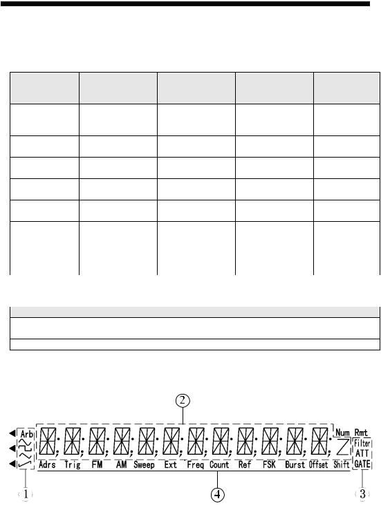
3.1.2 Display Annunciators:
Display areas:
Waveform Indication
Main Alphanumeric Display
Frequency Measurement/Totalize SettingsInstrument states
12

4080 series Arbitrary/Function Generator with Counter –Instruction Manual
Waveform states
Sine waveform is enabled (,main waveform)
Square waveform is enabled (main waveform)
Triangle waveform is enabled
Ramp waveform is enabled
Arb Arbitrary waveform mode is enabled
Frequency Measurement/Totalize states
Filter: |
Low Pass Filter is enabled |
ATT: |
Input Attenuator is enabled |
GATE: |
Gate received trigger |
Function Generator states |
|
Adrs: |
The instrument is in remote state. |
Trig: |
Function Generator is waiting for a single trigger or external trigger. |
FM: |
FM modulation is enabled |
AM: |
AM modulation is enabled |
Sweep: |
Sweep mode is enabled |
Ext: |
Generator is configured for external signal input |
Freq: |
Frequency measurement function is enabled |
Count: |
Totalize function is enabled |
FSK: |
FSK (frequency shift keying) modulation is enabled |
◄FSK: |
PSK modulation is enabled |
Burst: |
Burst mode enabled. |
Offset: |
DC offset of output signal is not 0. |
Shift: |
Shift key has been pressed, Shift mode is active |
Rmt: |
The instrument is in remote state. |
3.13 Description of front panel keys
shift key
Access secondary functions or to enter units “seconds”, Vpp and “N”
Numerical key pad:
Keys are used for direct entry of numerical values. Keys 0 ● - are assigned secondary functions to enter the systems menu, reset the unit to its default values or revert to Standard Waveform (“SW”) mode.
◄ ► arrow keys
The primary function is to move the flashing digit left or right or to select the desired arbitrary waveform from the Arb List (secondary function). When in Counter Mode, these 2 keys are used to start/stop or reset/resume the counter.
Freq/Period key:
Toggle between frequency and period display (primary function) or to enable sine waveform.
Ampl/Pulse Width key:
Display and adjust the amplitude of waveforms or, when in pulse mode, toggle the display
13

4080 series Arbitrary/Function Generator with Counter –Instruction Manual
between amplitude and pulse width. The secondary function activates the square waveform
FSK/PSK key:
Toggle between FSK and PSK modulation (primary function). Activate triangle waveform
Menu key:
Enter modulation parameters for FSK, PSK, FM, AM and burst modulation and for sweep mode. When in standard waveform mode (no modulation, main waveforms enabled), this key can also be used to toggle the units for the amplitude display value between Vpp, Vrms and dBm. (Press the Amplitude key first, then the Menu key to toggle between the units). The secondary function enables the ramp waveform.
FM key:
Activate FM modulation (primary function). Enter Storage mode (secondary function). Enter units ms or mVpp after entering the desired value by numerical key pad. In Counter Mode, this key turns the input attenuator on or off.
AM key:
Activate AM modulation (primary function). The secondary function is used to recall and recreate signals stored in status memory. Enter units “MHz and “Vrms” after entering the desired value by numerical key pad. Enable the low pass filter when in Counter mode.
Sweep key:
Activate sweep mode. Select frequency measuring and totalize mode (secondary function) . Enter units kHz or mVrms after entering the desired numerical value directly via the keypad. Use the Shift key to toggle between frequency measurements and totalize mode.
Burst key:
Activate burst mode (primary function). Enter DC offset mode (secondary function). Enter units Hz or dBm. When in frequency measurement mode, press this key to enter the gate time.
Output key
Press this key to toggle the main OUTPUT signal between the ON and OFF state. By default the output is turned on, indicated by the green LED and the currently active wave form is available at the OUTPUT terminal. In Burst or Sweep mode, this key is also used to generate a single trigger.
3.14 Description of menu parameters
Use this key to configure modulation parameters, sweep mode parameters and system parameters. Modulation and Sweep mode: After enabling modulation or sweep mode, press “menu” to configure the related parameters. Each time you press the menu key, the parameter will flash for 1 second, followed by the currently active value of that parameter. Use the knob or numerical keys to enter a new value. Once the parameter is set, press menu to advance to the next parameter. Continue pressing the menu key to cycle through all parameters. Press Shift SW to return to the main waveform mode and to set the carrier waveform parameters.
Sweep Mode:


 MODE
MODE —
— >
> START
START F
F —
— >
> STOP
STOP F
F —
— >
> TIME
TIME —
— >TRIG
>TRIG


14

4080 series Arbitrary/Function Generator with Counter –Instruction Manual
MODE: Select LINEAR or LOGarithmic sweep
START F :Sweep start frequency
STOP F: Sweep stop frequency
TIME: Sweep time
TRIG: Select trigger source, INTernal or EXTernal
FM modulation:


 FM
FM DEVIA
DEVIA —
— >
> FM
FM FREQ
FREQ —>
—> FM
FM WAVE
WAVE —
— >
> FM
FM SOURCE


FM DEVIA: Peak frequency deviation FM FREQ: Modulating signal frequency
FM WAVE: Modulating signal waveform (sine, square, triangle rising or falling ramp) FM SOURCE:Toggle between internal and external modulating signal.
AM modulation:


 AM
AM LEVEL
LEVEL —> AM
—> AM FREQ
FREQ —
— >
> AM
AM WAVE
WAVE —
— >
> AM
AM SOURCE


AM LEVEL: Modulation depth
AM FREQ: Frequency of modulating signal
AM WAVE: Modulating signal waveform (sine, square, triangle rising or falling ramp) AM SOURCE Select internal or external modulating signal
Burst modulation:


 TRIG
TRIG —> COUNT
 —
— >
> SPACE
SPACE T
T —
— >
> PHASE
PHASE


TRIG Select trigger source, internal or external
COUNT: Number of burst cycles
SPACE T:Burst time spacing
PHASE: starting phase of the burst
FSK modulation:


 START
START F
F —>
—> STOP
STOP F—
F— >
> SPACE
SPACE T
T —
— >
> TRIG
TRIG


START F |
Primary frequency (same as carrier wave) |
STOP F |
the second frequency (hop frequency) |
SPACE T |
FSK rate |
TRIG |
Select trigger source, external or internal |
PSK modulation


 P1
P1 —
— >
> P2
P2 —
— >
> SPACE
SPACE T
T —
— >
> TRIG
TRIG


P1 |
phase value #1 |
P2: |
phase value #2 |
15

4080 series Arbitrary/Function Generator with Counter –Instruction Manual
SPACE T: |
PSK rate |
TRIG: |
trigger mode, internal or external |
System Function Mode:


 POWER
POWER ON
ON —
— >
> ADDRESS
 —>
—> OUT
OUT Z
Z
 —
— >
> INTERFACE
 —
— >…..
>…..


 …………BAUD
 —>
—> PARITY


POWER ON |
“Power on” state |
ADDRESS: |
set GPIB address (option) |
OUT Z: |
Configure amplitude display value for 50Ω or high impedance load termination |
INTERFACE: Select RS232 or GP-IB (IEEE-488) interface (option) |
|
BAUD: |
Baud rate for the RS232 interface |
PARITY: |
Parity and Data Bits configuration for RS232 |
16

4080 series Arbitrary/Function Generator with Counter –Instruction Manual
3.2 REAR PANEL
Ext. Trig/FSK/Burst:
Input Terminal for external trigger signals for FSK/PSK Burst modulation and sweep mode
MOD In
Apply modulating signal for AM and FM to this Input terminal
Meas Freq/TOT In
Input terminal for Universal Counter which operates in frequency measurement or Totalize mode
MOD OUT
The internally generated modulating signal when in AM mode will be available at this output
RS232C
RS232 interface for remote control of instrument (all models) or for download of custom arbitrary waveforms (models 4084AWG and 4086AWG only)
AC Socket and fuse compartment
Connect the supplied power line cord to this receptacle. Make sure to install the appropriate fuse according to the selected AC voltage.
AC Input Selector switch
Set this switch to the corresponding AC voltage in your area
17

4080 series Arbitrary/Function Generator with Counter –Instruction Manual
4. OPERATING INSTRUCTIONS
4.1 Installation
This section contains installation information, power requirements and initial inspection and signal connections for the 4080 series generators.
Mechanical Inspection
This instrument was carefully inspected before shipment. Upon receipt, inspect the instrument for damage that might have occurred in transit. If any sign of damage is found, notify your B+K Precision distributor.
Instrument Mounting
The 4080 Series is intended for bench use. The instrument includes a handle adjustable for optimum panel viewing angle. The instrument does not require special cooling when operated within conventional temperature limits.
Power Requirements
The 4080 Series can be operated from any source of 99V to 242V AC and frequency of 48Hz to 63Hz. The maximum power consumption is 35 VA. Replace fuses with the same type, according to the rating indicated on the rear panel of the instrument.
The instrument power fuse is located in a fuse compartment below the AC input receptacle. To access the fuse, first disconnect the power cord and then remove the fuse cartridge.
Power-on procedure
Turn on the instrument by pressing the power key on the front panel of the unit. The display should be flashing “BK PRECISION” for 2 seconds followed by the model number. e.g. .“4084AWG” for 1 second. By default, the instrument will enter the standard waveform (“SW”) mode with the frequency set to 10.00000000 kHz and the waveform annunciator displaying the “~ “ symbol. If the Power ON configuration in the systems menu was modified, the parameters of the last operation before power-down will be displayed.
4.2. Main operating modes
“SW” standard waveform mode
In this mode, the generator outputs any of the 27 build-in waveforms, including the 2 “main waveforms” sine and square. This also includes the 8 user programmable arbitrary waveforms (models 4084AWG and 4086AWG only). For most waveforms, you can set frequency, amplitude and DC offset. In this mode, modulation and sweep is not active and all annunciators in status area 4 are turned off. When modulation or sweep is enabled, press shift SW to return to this mode.
Modulation, Pulse and Sweep Mode
In this mode, the generator operates like a conventional function generator and the Arb annunciator is turned off. The user can select one of the modulation modes AM, FM, FSK, PSK, Burst or sweep mode. The 2 main waveforms sine and square can be used as carrier signal.
There is a close, reciprocal relationship between the modulation/sweep mode and the standard
18
 Loading...