


 Loading...
Model 1685B, 1687B, 1688B
Switching DC Power Supply
1 Safety Summary
The following safety precautions apply to both operating and maintenance personnel and must be observed during all phases of operation, service, and repair of this instrument. Before applying power, follow the installation instructions and become familiar with the operating instructions for this instrument.
GROUND THE INSTRUMENT
To minimize shock hazard, the instrument chassis and cabinet must be connected to an electrical ground. This instrument is grounded through the ground conductor of the supplied, three-conductor ac power cable. The power cable must be plugged into an approved three-conductor electrical outlet. Do not alter the ground connection. Without the protective ground connection, all accessible conductive parts (including control knobs) can render an electric shock. The power jack and mating plug of the power cable meet IEC safety standards.
DO NOT OPERATE IN AN EXPLOSIVE ATMOSPHERE
Do not operate the instrument in the presence of flammable gases or fumes. Operation of any electrical instrument in such an environment constitutes a definite safety hazard.
KEEP AWAY FROM LIVE CIRCUITS
Instrument covers must not be removed by operating personnel. Component replacement and internal adjustments must be made by qualified maintenance personnel. Disconnect the power cord before removing the instrument covers and replacing components. Under certain conditions, even with the power cable removed, dangerous voltages may exist. To avoid injuries, always disconnect power and discharge circuits before touching them.
DO NOT SERVICE OR ADJUST ALONE
Do not attempt any internal service or adjustment unless another person, capable of rendering first aid and resuscitation, is present.
DO NOT SUBSTITUTE PARTS OR MODIFY THE INSTRUMENT
Do not install substitute parts or perform any unauthorized modifications to this instrument. Return the instrument to B&K Precision for service and repair to ensure that safety features are maintained.
1

WARNINGS AND CAUTIONS
WARNING and CAUTION statements, such as the following examples, denote a hazard and appear throughout this manual. Follow all instructions contained in these statements.
A WARNING statement calls attention to an operating procedure, practice, or condition, which, if not followed correctly, could result in injury or death to personnel.
A CAUTION statement calls attention to an operating procedure, practice, or condition, which, if not followed correctly, could result in damage to or destruction of parts or the entire product.
WARNING: |
Do not alter the ground connection. Without the protective ground |
|
|
connection, all accessible conductive parts (including control knobs) |
|
|
can render an electric shock. The power jack and mating plug of the |
|
|
power cable meet IEC safety standards. |
|
WARNING: |
To avoid electrical shock hazard, disconnect power cord before |
|
|
removing covers. Refer servicing to qualified personnel. |
|
CAUTION: |
Before connecting the line cord to the AC mains, check the rear panel |
|
|
AC line voltage indicator. Applying a line voltage other than the |
|
|
indicated voltage can destroy the AC line fuses. For continued fire |
|
|
protection, replace fuses only with those of the specified voltage and |
|
|
current ratings. |
|
CAUTION: |
This product uses components which can be damaged by electro- |
|
static discharge (ESD). To avoid damage, be sure to follow proper |
||
|
||
|
procedures for handling, storing and transporting parts and |
|
|
subassemblies which contain ESD-sensitive components. |
SAFETY SYMBOLS
This symbol on an instrument indicates that the user should refer to the operating instructions located in the manual.
Certification
We certify that this product met its published specifications at time of shipment from the factory.
2

Compliance Statements
Disposal of Old Electrical & Electronic Equipment (Applicable in the European Union and other European countries with separate collection systems)
This product is subject to Directive 2002/96/EC of the European Parliament and the Council of the European Union on waste electrical and electronic equipment (WEEE), and in jurisdictions adopting that Directive, is marked as being put on the market after August 13, 2005, and should not be disposed of as unsorted municipal waste. Please utilize your local WEEE collection facilities in the disposition of this product and otherwise observe all applicable requirements.
3
Contents
1 |
Safety Summary........................................................................................ |
1 |
||
2 |
Introduction .............................................................................................. |
6 |
||
3 |
Controls and Indicators............................................................................. |
7 |
||
|
3.1 |
Front Panel........................................................................................ |
7 |
|
|
3.2 |
Rear Panel ......................................................................................... |
8 |
|
4 |
Operating Instructions .............................................................................. |
9 |
||
|
4.1 |
Using the Power Supply .................................................................. |
10 |
|
|
4.1.1 |
Connection .............................................................................. |
10 |
|
|
4.1.2 |
Self Test Sequence .................................................................. |
10 |
|
|
4.1.3 |
Control Knobs.......................................................................... |
12 |
|
|
4.1.4 |
Using Both Main and Auxiliary Outputs.................................. |
13 |
|
|
4.2 |
Control Modes ................................................................................ |
13 |
|
|
4.2.1 |
Normal Mode .......................................................................... |
14 |
|
|
4.2.2 |
Preset Mode............................................................................ |
14 |
|
|
4.2.3 |
Set Mode................................................................................. |
15 |
|
|
4.2.4 |
Analog Remote Control Mode ................................................ |
16 |
|
5 |
Remote Control....................................................................................... |
16 |
||
|
5.1 |
Analog Remote Control................................................................... |
16 |
|
|
5.1.1 |
Using Two External Variable DC Voltage Sources................... |
18 |
|
|
|
|
4 |
|
|
5.1.2 |
Using Two 5 kΩVariable Resistors.......................................... |
19 |
|
|
5.1.3 |
Enable and Disable the Output ............................................... |
20 |
|
5.2 |
PC Interface Control........................................................................ |
21 |
||
|
5.2.1 |
General Functions and Display................................................ |
21 |
|
|
5.2.2 |
External Timed Program ......................................................... |
22 |
|
|
5.2.3 |
Internal Preset Memory.......................................................... |
23 |
|
|
5.2.4 |
Data Log .................................................................................. |
24 |
|
|
5.2.5 |
Settings.................................................................................... |
26 |
|
|
5.2.6 |
Command Set.......................................................................... |
26 |
|
6 |
Faults and Troubleshooting .................................................................... |
31 |
||
6.1 |
OVP: Overvoltage Protection ......................................................... |
31 |
||
6.2 |
OTP: Overtemperature Protection................................................. |
31 |
||
6.3 |
OLP: Overload Protection............................................................... |
32 |
||
6.4 |
Fuse Replacement........................................................................... |
33 |
||
7 |
Specifications .......................................................................................... |
34 |
||
8 |
Certification ............................................................................................ |
36 |
||
9 |
Service Information ................................................................................ |
37 |
||
10 |
Limited Two-Year Warranty.................................................................... |
38 |
||
5
2 Introduction
B&K Precision models 1685B, 1687B, and 1688B are laboratory grade switching mode DC power supplies with high current output in a small form factor and lightweight package. The 1685B Series provides various configurations of output voltage and current, and make setting voltage and current levels fast and precise through its dual action, coarse/fine rotary encoder control knobs. In addition to its constant voltage (CV) and constant current (CC) modes, the high efficiency DC power supply offers a unique solution with its preset and analog remote control modes. Save up to three different presets of voltage and current values for quick recall. The analog remote control function allows the output power, voltage, and current to be adjusted without touching the front panel of the power supply. These features make the 1685B Series suitable for a wide range of applications including production testing, telecommunications, R&D, service, and university labs.
Features
•Automatic CV/CC crossover operation
•Lightweight and compact
•Rotary encoder control for precise voltage and current setting
•Save up to 3 user-defined voltage and current presets for quick recall
•PC software for remote control and external timed programming
•Analog remote control function
•USB interface
•Front panel auxiliary output
•Overvoltage, overtemperature, and overload protection
6

3 Controls and Indicators
3.1Front Panel
Figure 1 - Front Panel
(1)LED panel meter display with CV/CC indicator
(2)Rear Control Indicator (lights up when using Preset/Remote Control/Set mode)
(3)Output Voltage Control Knob (control main and auxiliary output voltage)
(4)Output Current Control Knob (control main and auxiliary output current limit)
(5)Power ON/OFF Switch
(6)Auxiliary Output Terminal (max 5 A)
Note: Please see Section 4.1.4 for more details on using both main and auxiliary output terminals together.
7
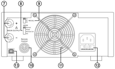
3.2Rear Panel
Figure 2 - Rear Panel
(7)Main Output Terminal (max 5 A for 1685B / 10 A for 1687B / 20 A for 1688B)
Note: Please see Section 4.1.4 for more details on using both main and auxiliary output terminals together.
(8)Mode Selection Switch (Normal, Preset, Remote Control, Set Modes)
(9)Recall Preset Selection Switch
(10)Analog Remote Control Terminal
(11)Cooling Fan Air Intake Grille
(12)AC Input Plug and Fuse Compartment
(13)USB Port (for PC remote control)
8
4 Operating Instructions
Safety Precautions
●This power supply is for indoor use only.
●Do not expose the power supply to sun, high humidity, or dusty environments.
●Never remove the metal cover of the power supply while AC power is connected.
●Never touch the unit when your hands are wet.
●Never block the ventilation slots and cooling fan air intake window.
●Never attempt to repair the power supply. Incorrect re-assembly may result in a risk of electric shock or fire.
●Never use the power supply for a load requiring higher current than the designed value. Otherwise it may damage the power supply.
●Place the power supply on a flat surface with sufficient clearance and dry, dust-free surroundings for ventilation.
This series has three models with different output voltage and current ranges. Make sure you have purchased the correct one.
Model Number |
Output Voltage Range |
Total Rated Current |
|
|
|
|
|
1685B |
1 – 60 V |
0 |
– 5 A |
|
|
|
|
1687B |
1 – 36 V |
0 |
– 10 A |
|
|
|
|
1688B |
1 – 18 V |
0 |
– 20 A |
|
|
|
|
|
Table 1 - Model Table |
||
9
4.1Using the Power Supply
4.1.1Connection
To connect the equipment to the power supply, follow the steps below.
1.Check the rating label of the power supply and confirm that it complies with your AC mains voltage.
2.Connect the power supply to the AC mains using the provided power cord and make sure the Mode Selection Switch is in the Normal position.
3.Hook up the red (+) terminal to the positive polarity input of the equipment and the black (-) terminal to the negative polarity input of the equipment.
4.Switch on the power supply first. The panel meter and green CV indicator should light up again.
5.Switch on the equipment. The panel meter and green CV indicator should still remain green.
6.When an operation is finished, switch off the equipment first and then switch off the power supply.
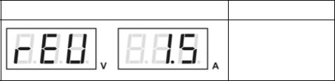
4.1.2Self Test Sequence
The power supply will perform a series of self checks when it is switched on. The table below shows the self test sequence.
Front Panel Display |
Test |
To show software version
10

Front Panel Display |
|
Test |
|
|
|
|
|
Segment check |
|
|
|
|
|
C.V. indicator check |
|
|
|
|
|
C.C. indicator check |
|
|
|
|
|
Rear control indicator |
|
|
check |
|
|
|
|
|
Return to C.V. |
|
|
|
|
|
Start power supply checks |
|
|
|
|
|
Overvoltage protection |
|
|
check |
|
|
|
|
|
Overload protection check |
|
|
|
|
11 |
|
Loading...