


4011A
1
INSTRUCTION
MANUAL
MANUAL DE
INSTRUCCIONES
MODEL 4011A
MODELO 4011A
5 MHz FUNCTION
GENERATOR
with DIGITAL DISPLAY
5MHz GENERADOR DE FUNCIONES
CON DIGITOS INDICADOR

2
TEST INSTRUMENT SAFETY
WARNING
Normal use of test equipment exposes you to a certain amount of danger from electrical shock because testing must sometimes be
performed where exposed voltage is present. An electrical shock causing 10 milliamps of current to pass through the heart will stop most
human heartbeats. Voltage as low as 35 volts dc or ac rms should be considered dangerous and hazardous since it can produce a lethal
current under certain conditions. Higher voltages pose an even greater threat because such voltage can more easily produce a lethal
current. Your normal work habits should include all accepted practices to prevent contact with exposed high voltage, and to steer current
away from your heart in case of accidental contact with a high voltage. You will significantly reduce the risk factor if you know and
observe the following safety precautions:
1. Don't expose high voltage needlessly. Remove housings and covers only when necessary. Turn off equipment while making test
connections in high-voltage circuits. Discharge high-voltage capacitors after removing power.
2. If possible, familiarize yourself with the equipment being tested and the location of its high voltage points. However, remember that
high voltage may appear at unexpected points in defective equipment.
3. Use an insulated floor material or a large, insulated floor mat to stand on, and an insulated work surface on which to place
equipment; and make certain such surfaces are not damp or wet.
4. Use the time proven "one hand in the pocket" technique while handling an instrument probe. Be particularly careful to avoid
contacting a nearby metal object that could provide a good ground return path.
5. When testing ac powered equipment, remember that ac line voltage is usually present on some power input circuits such as the on-
off switch, fuses, power transformer, etc. any time the equipment is connected to an ac outlet, even if the equipment is turned off.
(continued on inside back cover)

3
Instruction Manual
for
MODEL 4011A
5 MHz
FUNCTION
GENERATOR
with DIGITAL DISPLAY
22820 Savi Ranch Parkway • Yorba Linda, CA 92887-4610

4
TABLE OF CONTENTS
page
TEST INSTRUMENT ..................SAFETY inside front cover
INTRODUCTION . ............................................................. 5
SPECIFICATIONS ............................................................. 6
CONTROLS AND INDICATORS ...................................... 8
OPERATING INSTRUCTIONS .........................................10
Frequency and Waveform Selection....................................10
Considerations ...................................................................11
Duty Cycle Control ............................................................12
TTL/CMOS Output ...........................................................13
Voltage Controlled Frequency Operation ...........................13
Output Protection Guidebook.............................................14
page
MAINTENANCE ........................................ 15
Fuse Replacement ........................................ 15
Instrument Repair Service............................. 15
CUSTOMER SUPPORT ............................... 16
WARRANTY SERVICE INSTRUCTIONS ... 17
LIMITED TWO-YEAR WARRANTY .......... 18
SPANISH MANUAL.................................... 20

5
INTRODUCTION
The B+K Precision Model 4011A Function Generator
is a versatile signal source which combines several
functions into one unit. Additionally, the instrument
provides the added convenience of a built-in frequency
counter. This permits more accurate determination of
output frequency than is possible with a simple calibrated
dial. Coarse and fine tuning controls permit precision
settability of the output frequency. High stability assures
that the output frequency does not drift.
With this versatility, the unit has a vast number of
applications in both analog and digital electronics in the
engineering, manufacturing, servicing, educational, and
hobbyist fields.
The heart of the function generator is a VCG (voltage-
controlled generator) that produces precision sine, square,
or triangle waves over the 0.5Hz to 5MHz range. This
encompasses subaudible, audio, ultrasonic, and RF
applications. A continuously variable dc offset allows the
output to be injected directly into circuits at the correct bias
level.
Variable symmetry of the output waveform converts the
instrument to a pulse generator capable of generating
rectangular waves or pulses, ramp or sawtooth waves, and
slewed sine waves.
In addition to the above features, an external signal may
be used to sweep the output frequency or control operating
frequency. This is useful in situations where an externally
controlled frequency is desirable.

6
SPECIFICATIONS
FREQUENCY CHARACTERISTICS
Waveforms
Sine, Square, Triangle, ± Pulse, ± Ramp
Range
0.5Hz to 5MHz in 7 ranges
Resolution
4 digits
Tuning Range
Coarse: 10:1, Fine: ±5% of Coarse Setting
Variable Duty Cycle
15:85:15 Continuously Variable
Operating Modes
Normal, VCG (Voltage Controlled Generator)
Frequency Stability
Output frequency will not change more than 0.09% in 15
minutes after 1 hour warmup.
OUTPUT CHARACTERISTICS
Impedance
50 Ω ±10%
Level
20V p-p Open-circuit, 10V p-p into 50 Ω
Amplitude Control
Variable, 20dB range typical
Attenuation
-20 dB ±1 dB
DC Offset
Preset: ±0.1V typical
Variable: ±10V open-circuit, ±5V into 50 Ω
SINE WAVE
Distortion
3% typical at 1kHz
Flatness
±5% (.45 dB)
SQUARE WAVE
Symmetry
0.5Hz to 100kHz ≤2%
Rise Time
≤20nS
TRIANGLE WAVE
Linearity
≥98% to 100kHz

7
SPECIFICATIONS
NOTE: Specifications and information are subject to change without notice. Please visit www.bkprecision.com
for the most current product
information.
TTL OUTPUT
Level > 2.4V
Rise Time ≤20nS
Duty Cycle 50% typical
CMOS OUTPUT
Max Frequency 2MHz
Level 4V to 14V ±0.5V p-p,
Continuously variable
Rise Time ≤120nS
VCG (Voltage Controlled Generator) INPUT
Input Voltage
0 - 10V ±1V causes a 100:1 frequency change
Impedance
10 kΩ ±5%
FREQUENCY COUNTER
Accuracy
Time Base Accuracy ±1 count
Time Base Accuracy
±10 PPM (23 °C ±5 °C)
Display
4 digit LED
POWER SOURCE
120 / 230VAC ±10%, 50 / 60Hz, internal jumper
selectable
DIMENSIONS (H x W x D)
10-3/8" x 3-3/8" x 11-7/16" (26.4cm x 8.6cm x 29.1cm)
WEIGHT
4 lb. (1.8 kg.)
ACCESSORIES
Instruction Manual
Output Cable, BNC to Alligator Clips

8
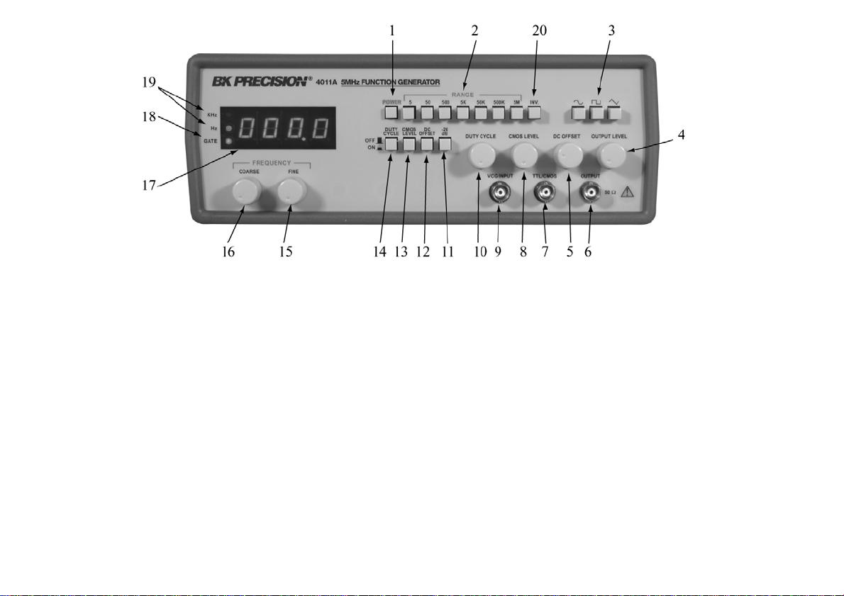
CONTROLS AND INDICATORS
FRONT PANEL (Refer to Fig. 1)
1. POWER Switch. Turns power on and off.
2. RANGE Switch. Selects output frequency range. Seven
ranges from 5Hz to 5MHz. Switch indicates maximum
frequency of range and is adjusted with COARSE
FREQUENCY control to 0.1 times the maximum. For
example, if the 500kHz range is selected, the output
frequency can be adjusted from 50kHz to 500kHz.
3. FUNCTION Switch. Selects sine, square, or triangle
waveform at OUTPUT jack.
4. OUTPUT LEVEL Control. Controls the amplitude of the
signal at the OUTPUT jack. Output level can be decreased
by approximately 20 dB with this control.
5. DC OFFSET Control. Enabled by the DC OFFSET
Switch (12). Clockwise rotation from center changes the
DC offset in a positive direction while counterclockwise
rotation from center changes the DC offset in a negative
direction.
6. OUTPUT Jack. Waveform selected by FUNCTION
switch as well as the superimposed DC OFFSET voltage
is available at this jack.
7. TTL/CMOS Jack. TTL or CMOS square wave,
depending on the position of the CMOS LEVEL
switch (13) is output at this jack. This output is
independent of the OUTPUT LEVEL and DC
OFFSET controls.
8. CMOS LEVEL Control. Rotating this control
clockwise increases the amplitude of the CMOS
square wave at the TTL/CMOS jack.
9. VCG Jack. Voltage Controlled Generator input.
Permits external control of generator output
frequency by a DC voltage input at this jack. A
positive voltage will decrease frequency.
10. DUTY CYCLE Control. Enabled by the DUTY
CYCLE Switch (14). Rotation from center position
adjusts the duty cycle of the main OUTPUT signal.
11. -20dB Switch. When engaged, the signal at the
OUTPUT jack is attenuated by 20dB.
12. DC OFFSET Switch. When engaged, enables
operation of the DC OFFSET control (5).
9
Figure 1. Model 4011A Controls and Indicators.
13. CMOS LEVEL Switch. When engaged, changes
the TTL signal to CMOS signal at the TTL/CMOS
jack.
14. DUTY CYCLE Switch. When engaged, enables
operation of DUTY CYCLE control (10).
15. FINE FREQUENCY Control. Vernier adjustment
of the output frequency for ease of setting frequency.
16. COARSE FREQUENCY Control. Coarse
adjustment of the output frequency from 0.1 to 1
times the selected range.
17. COUNTER DISPLAY. Displays frequency of internally
generated waveform.
18. GATE LED. Indicates when the frequency counter display is
updated. When the 50K through 5M ranges are selected, the
LED will flash 10 times per second (every 0.1 seconds).
When the 50 through 5K ranges are selected, the LED will
flash once every second and when the 5 range is selected, the
LED will flash every 10 seconds. As the LED turns off, the
display is updated.
19. Hz and KHz LED. Indicates whether the counter is reading
in Hz or kHz.
20 Inverter Switch
10
OPERATING INSTRUCTIONS
The B+K Precision Model 4011A Function Generator is a
versatile instrument, capable of producing a variety of output
waveforms over a broad range of frequencies. To gain a working
familiarity with the unit, it is recommended that it be connected
initially to an oscilloscope, so that the effects of the various controls
on the output waveforms can be observed. Use this manual as
required for reference until becoming accustomed to the operating
procedures.
FREQUENCY AND WAVEFORM SELECTION
l. Initially, verify that the DUTY CYCLE (14), CMOS LEVEL
(13), DC OFFSET (12), -20dB (11) switches are in the OUT
position (released). This will produce a symmetrical waveform
unaffected by the other controls.
2. Plug the unit into an appropriate power source and turn it on by
engaging the POWER switch (1).
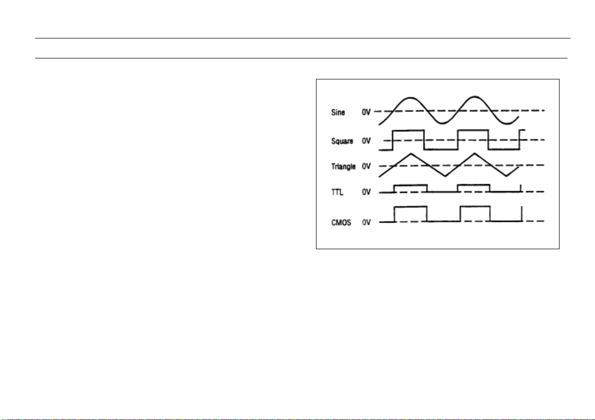
3. Select the desired waveform (SINE, SQUARE, or TRIANGLE)
by engaging one of the FUNCTION switches (3). Phase
relationships of the waveforms are shown in Fig. 2.
4. Select the frequency of the waveform by engaging one of the
RANGE switches (2). The output frequency is displayed, along
with the appropriate measurement units, kHz or Hz (19), on the
LED display.
5. Rotate the COARSE (16) frequency control to quickly set the
output frequency to the approximate desired value. The FINE
(15) frequency control can then be used to easily set the output
to the specific desired value. The frequency selected is available
at the OUTPUT jack (6). In addition, a digital signal, either TTL
or CMOS is available at the TTL/CMOS jack (7) (refer to the
“TTL/CMOS OUTPUT” section of this manual).
6. Adjust the amplitude of the output as desired using the
OUTPUT LEVEL control (4). Rotation of this control
varies the amplitude from maximum to 20dB below
maximum. An additional attenuation of -20dB is
available by pushing in the -20dB switch (11). The
attenuation factors can be combined for a total of -40dB.
The maximum si
g
nal level is 10V
p
-
p
(
into 50 Ω
)
.
Fi
g
ure 2. Out
p
ut Waveform and Phase Relationshi
p
11
OPERATING INSTRUCTIONS
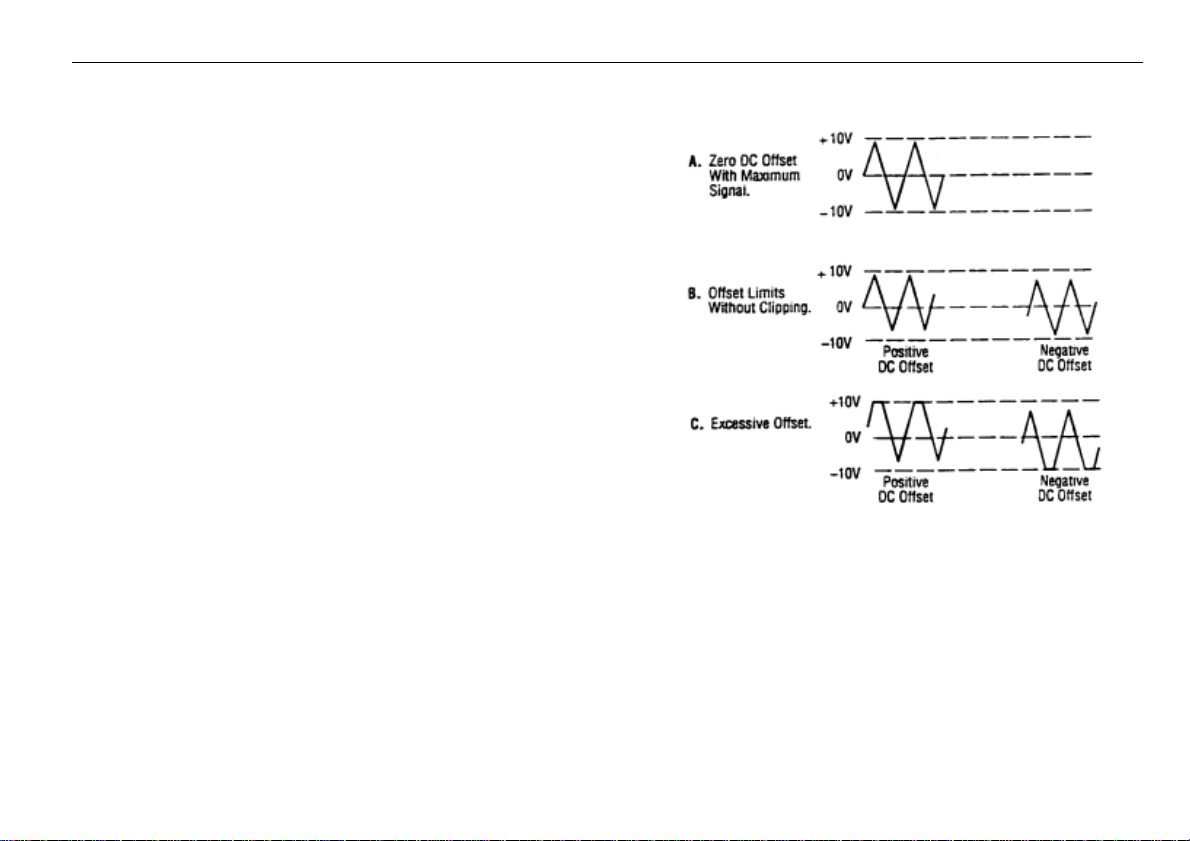
7. A superimposed DC component can be added to the output signal
by engaging the DC OFFSET switch (12) to enable operation of
the DC OFFSET control (5). Rotation of this control adds a
positive or negative DC component to the output signal. The DC
component introduced is independent of the OUTPUT LEVEL
control and can be varied by ±10 volts open circuited or ±5 volts
into 50Ω. The DC Offset does not affect the TTL/CMOS output
jack. The effect of DC OFFSET is shown in Fig. 3.
CONSIDERATIONS
1. l. Counterclockwise rotation of the COARSE frequency control
decreases the output frequency to approximately one-tenth of the
maximum for the range selected (10:1). For example, if the 50K
range is selected and the COARSE frequency control is set to
full counterclockwise, the output frequency is approximately
5kHz.
2. It is advisable to set the FINE frequency control to the
approximate center of its rotation before setting the COARSE
frequency control. This assures that the FINE control will not
reach its limit while trying to finalize the frequency setting.
3. The FINE frequency control provides approximately ±5%
frequency deviation from the COARSE control setting. This
provides vernier adjustment to easily set the frequency to a
precise value.
4. . When the 5Hz range is selected, the gate time is 10 seconds and
the display is updated once every 10 seconds. The result of a
frequency change will not be displayed until 10 seconds later.
Adjust the frequency in progressively smaller steps, waiting for
the display to update until the desired frequency is obtained.
5. When outputting square waves or when using the TTL output,
terminate the cable into 50Ω to minimize ringing. Also, keep
cables as short as possible.
Figure 3. Use of DC OFFSET Control
6. Remember that the output signal swing of the
generator is limited to ±10 volts open circuited or ±5
volts into 50Ω, and applies to the combined peak-to-
peak signal and DC offset. Clipping occurs slightly
above these levels. Fig. 3 illustrates the various
operating conditions encountered when using the DC
offset. If the desired output signal is large or if a large
DC offset is required, an oscilloscope should be used
to make sure that the desired signal is obtained without
undesirable clipping.
12
OPERATING INSTRUCTIONS
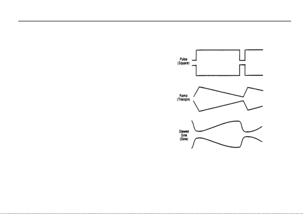
DUTY CYCLE CONTROL
The DUTY CYCLE control can be used to alter the
symmetry of the output waveform, to produce
waveshapes such as those shown in Fig. 4. For a
square wave, symmetry variation amounts to changing
the duty cycle (ratio of "high" to "low" time),
effectively converting the instrument into a pulse
generator. For a triangle wave, the result is a ramp, and
with a sine wave, a distorted waveshape called a
slewed sine is produced. The Model 4011A provides
for symmetry variation from 15% to 85%.
1. Select the waveform desired either SINE,
SQUARE or TRIANGLE.
2. Engage the DUTY CYCLE switch (14) and adjust
the DUTY CYCLE control (10) for the desired
waveshape. Clockwise rotation from center results
in an increase in square wave duty cycle, and
changes the sine and triangle waves as shown in
the top waveform of each pair of Fig. 4. Counter-
clockwise rotation results in the bottom waveform
in each pair.
3. Varying the duty cycle setting results in a slight
change in frequency. Adjust the COARSE and
FINE frequency controls as required.
Figure 4. Effects of Symmetry
Variation.
 Loading...