


INSTRUCTION |
|
MANUAL |
MODELS: 1760A, 1761, 1762 |
Triple Output
DC POWER SUPPLY
With Dual 4-Digit LED Displays

TEST INSTRUMENT SAFETY
WARNING
Normal use of test equipment exposes you to a certain amount of danger from electrical shock because testing must sometimes be performed where exposed high voltage is present. An electrical shock causing 10 milliamps of current to pass through the hear t will stop most human heartbeats. Voltage as low as 35 volts DC or AC rms should be considered dangerous and hazardous since it can produce a lethal current under certain conditions. Higher voltages are even more dangerous. Your normal work habits should include all accepted practices to prevent contact with exposed high voltage, and to steer c urrent away from your heart in case of accidental contact with a high voltage. Observe the following safety precautions:
1.There is little danger of electrical shock from the DC output of this power supply. However, there are several other possible test conditions using this power supply that can create a high voltage shock hazard:
a.If the equipment under test is the “hot chassis” type, a serious shock hazard exists unless the equipment is unplugged (just turning off the equipment does not remove the hazard), or an isolation transformer is used.
b.If the equipment under test is “powered up” (and that equipment uses high voltage in any of its circuits), the power supply outputs may be floated to the potential at the point of connection. Remember that high voltage may appear at unexpected points in defective equipment. Do not float the power supply output to more than 100 volts peak with respect to chassis or earth ground.
c.If the equipment under test is “off” (and that equipment uses high voltage in any of its circ uits under normal operation), discharge high-voltage capacitors before making connections or tests. Some circuits retain high voltage long after the equipment is turned off.
2.Use only a polarized 3-wire AC outlet. This assures that the power supply chassis, case, and ground terminal are connected to a good earth ground and reduces danger from electrical shock.
3.Don’t expose high voltage needlessly. Remove housings and covers only when necessary. Turn off equipment while making test connections in high-voltage circuits. Discharge high-voltage capacitors after removing power.
(continued on inside back cover)
2

Instruction Manual
For Models 1760A, 1761, 1762
Triple Output DC Power Supplies With Dual 4-Digit LED Displays
22820 Savi Ranch Parkway
Yorba Linda, CA 92887
www.bkprecision.com
3

TABLE OF CONTENTS
|
page |
TEST INSTRUMENT SAFETY------------- |
inside front cover |
INTRODUCTION------------------------------------------------ |
5 |
FEATURES ------------------------------------------------------- |
7 |
SPECIFICATIONS ---------------------------------------------- |
8 |
CONTROLS AND INDICATORS ---------------------------- |
10 |
General Controls and Indicators ------------------------------- |
10 |
4-6.5 V Supply Controls and Indicators ---------------------- |
10 |
“A” Supply Controls and Indicators--------------------------- |
12 |
“B” Supply Controls and Indicators --------------------------- |
12 |
Rear Panel Controls --------------------------------------------- |
13 |
OPERATING INSTRUCTIONS------------------------------- |
14 |
Safety Precautions----------------------------------------------- |
14 |
Equipment Precautions ----------------------------------------- |
14 |
Independent Use of “A” or “B” Supply----------------------- |
14 |
Hook-up ---------------------------------------------------------- |
15 |
Typical Constant Voltage Operation -------------------------- |
18 |
Setting Current Limit ------------------------------------------- |
19 |
Typical Constant Current Operation -------------------------- |
20 |
Constant Voltage/Current Characteristic --------------------- |
21 |
Series Tracking Operation-------------------------------------- |
22 |
Parallel Tracking Operation ------------------------------------ |
26 |
4-6.5 V Power Supply Operation ------------------------------ |
29 |
|
Page |
APPLICATION ---------------------------------------------------- |
33 |
General -------------------------------------------------------------- |
33 |
Electronics Servicing ---------------------------------------------- |
33 |
Electronics Manufacturing ---------------------------------------- |
33 |
Electronics Design Lab -------------------------------------------- |
34 |
Electronics Education --------------------------------------------- |
34 |
Battery Charging --------------------------------------------------- |
34 |
Split Supply--------------------------------------------------------- |
34 |
MAINTENANCE -------------------------------------------------- |
41 |
Fuse Replacement -------------------------------------------------- |
41 |
Line Voltage Conversion ------------------------------------------ |
41 |
Adjustments -------------------------------------------------------- |
42 |
“A” Supply and “A” Metering Adjustments -------------------- |
42 |
4-6.5 V Supply and 6.5 V Metering Adjustments -------------- |
44 |
“B” Supply and Metering Adjustments -------------------------- |
44 |
“B” Series Tracking Adjustment --------------------------------- |
45 |
Instrument Repair Service ---------------------------------------- |
45 |
WARRANTY SERVICE INSTRUCTIONS -------------------- |
46 |
LIMITED TWO-YEAR WARRANTY -------------------------- |
47 |
4

INTRODUCTION
These B+K Precision Triple Output DC Power Supplies are high quality, general purpose DC power sources. They provide two “main” supplies and a “third” auxiliary output with a 4-6.5V (2-6.5V for models 1761 & 1762) DC output. The “main” V supplies are adjustable with both coarse and fine voltage controls for precise settability and are capable of current output of 0-2A (0-3A for model 1761). The “third” supply has a current output of 0-5A, allowing it to handle extensive digital logic circuitry. Two large panel-mounted LED meter displays can monitor either the output current or output voltage of each supply.
The two “main” volt supplies can be operated independently or in one of two tracking modes. In the series tracking mode, the “B” Supply tracks from 5% to 100% of the voltage of the “A” Supply. Maximum current setting of the two supplies can still be set independently when in the series tracking operating mode. In the series tracking mode the
“A” and “B” supplies are connected in series, allowing for double the voltage setting. In the parallel tracking mode, the two supplies are connected together in parallel, allowing for double the current setting.
Both “main” volt supplies may be used in constant voltage or constant current applications. The crossover from constant voltage to constant current modes is smooth and automatic. LED’s indicate the “CV” (constant voltage) or “CC” (constant current) mode of operation.
In constant voltage applications, a current limit may be preset. When load variations cause the current to reach the preset limit, the unit then regulates output current rather than output voltage. Current limits are adjustable from 5% to 100% of maximum.
In constant current applications, the maximum voltage may be preset. When load variations cause current to drop below the regulated value, the unit reverts to regulated voltage operation at the preset value.
The “third” V supply is ideal for powering digital logic circuitry. The 0-5 amp capacity allows the supply to be used for large circuits. Built-in overload protection automatically limits the current output to a maximum of 5 amps. An indicator lights when the supply is overloaded.
These models exhibit excellent regulation and low ripple characteristics. The circuit design incorporates a pre-regulator, which greatly reduces internal power dissipation at low output voltages.
Reverse polarity protection prevents accidental damage to the power supply from improper connection to an external voltage, and current limiting protects the equipment being powered, as well as the power supply.
The output is isolated from chassis and earth ground, which permits full flexibility of connections. When needed, the (+) or (-) polarity may be strapped to ground, or either polarity may be floated to an external voltage. Additionally, the two
“main” volt supplies can be used as a “split supply” with two positive voltages and a common negative, two negative voltages and a common positive, or one positive, one negative, and a common. All of these configurations can be used with either matching (tracking) or differing (independent) voltages.
5

The features and versatility of the unit, especially the triple output and tracking features, make it an ideal general purpose power supply for engineering lab applications. It can serve as a single or multi-voltage power source, including the bias supply, for breadboard and prototype circuits and equipment. It can provide single or simultaneously varying voltages for circuit evaluation. It can provide tracking (+) and (-) voltages for evaluating differential amplifiers. It may be used as a battery eliminator, or to power individual circuit boards or cards while removed from the system. Its output can be evaluated while powering a breadboard or prototype circuit to determine the circuit’s power supply requirements. Its laboratory quality specifications will meet most engineering laboratory requirements.
The same features that make the Model 1760A a good choice for an engineering lab also make it a good choice for most other solid state electronic applications. These applications include service shops; industrial production testing of components, assemblies, and complete equipment; for school laboratories, and home use by electronic hobbyists.
6

FEATURES
TRIPLE OUTPUT
Operates as three separate power supplies. Each has floating output and is completely isolated from the other two.
ONE 4-6.5 V (1760A) or 2-6.5 V (1761 & 1762) SUPPLY
Durable 0-to-5 amp supply is ideal for use with most digital logic circuitry. Adequate current capacity for extensive circuitry.
TWO 0-30V (model 1760A), 0-35V (model 1761), or 0-60V (model 1762) SUPPLIES
“A” and “B” supply are continuously variable over their respective voltage ranges with coarse and fine controls. Each supply has a 2A (3A model 1761) current capacity.
UNIQUE TRACKING FEATURE
CONSTANT VOLTAGE OR CONSTANT CURRENT
The “A” and “B” supplies provide regulated DC voltage output or regulated DC current output. Crossover is smooth and automatic.
LED DISPLAY
Two large, easy-to-read LED 4-digit displays monitor output voltage or output current of all three supplies. Use of two meters allows simultaneous current and voltage metering when using “A” and “B” supplies in tracking operation. Good visibility in bright or low light.
LABORATORY QUALITY
Excellent regulation, low ripple.
The “A” and “B” supplies can be operated so that the “B” supply |
|
PRE-REGULATOR |
tracks the “A” supply. Outputs can be strapped for two positive |
|
Limits internal dissipation for higher reliability and |
voltages with a common negative, two negative voltages with a |
|
efficiency. |
common positive, or one positive and one negative with a neutral |
|
|
common. |
|
ISOLATED OUTPUT |
|
|
Either polarity may be floated or grounded. |
SINGLE 0-60V (model 1760A), 0-70V (model 1761), or 0- |
|
|
120V (model 1762) SUPPLY |
|
OVERLOAD PROTECTION |
Series tracking feature doubles output voltage capability and |
|
Fully adjustable current limiting (from 5% to 100% of |
allows use of “A” and “B” supplies combined as one supply. |
|
maximum output current) for “A” and “B” supplies protects |
|
|
circuit under test and the power supply. |
SINGLE 0-30V, 4A (model 1760A), 0-35V, 6A (model |
|
|
1761), or 0-60V, 4A (model 1762) SUPPLY |
|
REVERSE POLARITY PROTECTION |
Parallel tracking feature doubles output current capability and |
|
Prevents damage to power supply from external voltage of |
allows use of “A” and “B” supplies combined as one supply. |
7 |
reverse polarity. |
|
|

SPECIFICATIONS
“A” AND “B” SUPPLIES
Output Voltage Range:
0V to 30V (model 1760A)
0V to 35V (model 1761)
0V to 60V (model 1762) Output Current Limit Range:
0.1A to 2A (model 1760A and 1762)
0.1A to 3A (model 1761)
Load Regulation (Constant Voltage):
≤0.01% + 3 mV
Line Regulation 108 - 132 V (Constant Voltage):
≤0.01% + 3 mV
Ripple (Constant Voltage):
≤1 mV RMS
Recovery Time (Constant Voltage):
≤100 uS
Temp. Coefficient (Constant Voltage): <300 ppm/°C
Load Regulation (Constant Current):
≤0.2% + 3mA
Line Regulation 108 - 132 V (Constant Current):
≤0.2% + 3mA
Ripple Current (at 108 V for Constant Current):
≤3mA RMS
Tracking (Series) Accuracy: ±0.2% + 10mV
Tracking Series, “B” tracks “A”:
5% to 100%
Panel Meter Accuracy (Volts): ±0.5% + 9 digits.*
Panel Meter Accuracy (Current): ±0.5% + 9 digits.*
(* see note 1)
“Third” SUPPLY
Output Voltage Range:
4V to 6.5V (2V to 6.5V model 1761)
Load Regulation (Constant Voltage):
≤10mV (0 to 5A load)
Line Regulation 108 - 132V (Constant Voltage):
≤10mV
Ripple and Noise:
≤2mV RMS
Over Voltage Protection Threshold:
6.8V to 7.3V
Panel Meter Accuracy:
Same as “A” Supply Meter.
8

SPECIFICATIONS
GENERAL
AC Input:
Domestic: 120 VAC + 10%, 60 Hz
International: 120/220/230/240 VAC -* 10%, 50/60 Hz
Power Consumption (Fully Loaded):
Approximately 350 W
Protection:
Reverse polarity protection and current limiting.
Dimensions (H x W x D):
5.7" x 10.5" x 15" (145 mm x 267 mm x 381 mm)
Weight:
10 kg (21 lbs)
Accessories Supplied:
Two earth ground bus straps.
NOTE: Specifications and information are subject to change without notice. Please visit www.bkprecision.com for the most current product information.
Note 1:
Important: Even with noticeable Thermal Drift, this high resolution power supply will be considerably more accurate than any standard three digit display bench power supply.
Thermal Drift: Since this power supply has greater resolution than standard bench power supplies they are more susceptible to Thermal Drift. Thermal Drift occurs on almost every type of power supply but is more apparent on high resolution types. Thermal Drift results in the metering of the power supply to either slowly increase or decrease with the change in the power supply’s internal temperature. As the power supply outputs more power its internal temperature will increase causing the metering (primarily the current) to slowly increase. As the power demand is deceased the power supply will cool causing the metering (primarily the current) to slowly decrease. If the power supply remains with a constant output of power for more than fifteen minutes the power supply metering will remain constant and should not continue to drift.
9

CONTROLS AND INDICATORS
GENERAL CONTROLS AND INDICATORS
1.POWER Switch. Turns power on and off.
2.TRACKING Mode Switches. Two pushbutton switches that select INDEPendent mode, SERies tracking mode, or PARallel tracking mode as follows:
a.When INDEP/TRACK switch is disengaged (out), the unit is in the INDEPendent mode and the “A” and “B” power supplies are completely independent from one another.
b.When the INDEP/TRACK switch is engaged (in) and the SER/PAR switch is disengaged (out), the unit is in the TRACKing SERies mode. In this mode, maximum voltage of both supplies is set using the “A” VOLTAGE controls (voltage at output terminals of the “B” supply tracks the voltage at the output terminals of the “A” supply).
Also, in this mode of operation the positive terminal (red) of the “B” supply is internally connected to the negative terminal (black) of the “A” supply. This allows the two supplies to be used as one 0-to-60 volt supply.
c.When both INDEP/TRACK and SER/PAR switches are engaged (in), the unit is in the TRACKing
PARallel mode. In this mode the “A” and “B” supplies are wired together in parallel and both the maximum current and voltage are set using the “A” controls. The “A” and “B” outputs can be used as two individual (but tracking) power supplies or just the “A” output can be used as a 0-to-30 volt supply with a 4 A capability.
10
3.0-30V/4-6.5V Switch. Controls “A”/4-6.5V LED Display. When this switch is in the 0-30V position (out), the LED display monitors the “A” (0-30 V) supply. When this switch is in the 4-6.5V position (in), the LED display monitors the 4-6.5V supply.
4.Right V/A Switch. Selects current or voltage metering mode for the “A” 0-30 V supply or the 4-6.5 V supply (depending on setting of 0-30 V/4-6.5 V switch). When in the A (amps) position (in), current is read from the “A”/4-6.5 V LED Display. When in the V (volts) position (out), voltage is read from the “A”/ 4-6.5 V LED Display.
5.“A”/4-6.5 V LED Display. Digital display indicates voltage or current at the 0-30 V “A” supply or the 4-6.5 V supply (depending on the setting of the Right V/A and
0-30 V/4-6.5 V switches).
4-6.5 V SUPPLY CONTROLS AND INDICATORS
6.“-” Terminal (Black). Negative polarity output terminal for 4-6.5V supply.
7.“+” Terminal (Red). Positive polarity output terminal for 4-6.5V supply.
8.Voltage Level Control. Adjusts output voltage for 4- 6.5V supply. Fully counterclockwise rotation adjusts output voltage to 4V. Clockwise rotation increases voltage to a maximum of 6.5V (full clockwise rotation).
9.5 A OVERload Indicator. Lights when load on 4-6.5 Volt supply becomes too large.

CONTROLS AND INDICATORS
Fig. 1. Front Panel Controls and Indicators.
11

CONTROLS AND INDICATORS
“A” SUPPLY CONTROLS AND INDICATORS
10.C.C. (Constant Current) Indicator. Red LED lights when
“A” supply is in the Constant Current mode. The Power Supply regulates the output current at the value set by the “A” CURRENT control. In the Parallel Tracking mode, when this indicator is lit, both the “A” and “B” supplies are in the Constant Current mode.
11.C.V. (Constant Voltage) Indicator. Green LED lights when the “A” supply is in the Constant Voltage mode. The Power Supply regulates the output voltage at the value set by the “A” VOLTAGE controls. In either the Series or Parallel Tracking mode, when this indicator is lit, both the “A” and “B” supplies are in the Constant Voltage mode.
12.Coarse VOLTAGE Control. Coarse adjustment of the output voltage of the “A” supply. Also functions as coarse adjustment control for the maximum output voltage of the “B” supply when either parallel or series tracking mode is selected. Read the value on the “A”/4-6.5 V LED Display when the voltage (V) and master (0-30 V) metering modes are selected.
13.Fine VOLTAGE Control. Fine adjustment of output voltage of the “A” supply. Also functions as fine adjustment control for the maximum output voltage of the “B” supply when either parallel or series tracking mode is selected. Read the value on the “A”/4-6.5 V LED Display when the voltage (V) and master (0-30 V) metering modes are selected.
14.CURRENT Control. Adjusts current limit of “A” supply in constant voltage mode. Adjusts constant current value of “A” supply in constant current mode. Current can be read from the “A”/4-6.5V LED Display when the current (A) and master (0-30V) metering modes are selected.
15.“+” Terminal (Red). Positive polarity output terminal for the “A” supply. Also serves as the positive polarity terminal for 4 A parallel and 0-to-60 V series tracking operation.
16. Terminal (Green). Earth and Chassis Ground.
17.“-” Terminal (Black). Negative polarity output terminal for the “A” supply. Also serves as the negative polarity terminal for 4 A parallel tracking operation. In series tracking operation, this terminal is internally tied to the (+) positive terminal of the “B” supply.
“B” SUPPLY CONTROLS AND INDICATORS
18.C.V. (Constant Voltage) Indicator. Green LED lights when the “B” supply is in the Constant Voltage mode. The Power Supply regulates the output voltage at the value set by the “B” VOLTAGE controls.
19.C.C. (Constant Current)/PARallel Indicator. Red LED lights when “B” supply is in the Constant Current mode. The Power Supply regulates the output current at the value set by the “B” CURRENT control when in the series tracking or INDEPendent modes. Also lights when the TRACKing PARallel mode is selected.
12
CONTROLS AND INDICATORS
20.Coarse VOLTAGE Control. Coarse adjustment of the output voltage of the “B” supply when the INDEPendent mode is selected. Also sets the 5% to 100% tracking in the SERies TRACKing mode. Disabled in the PARallel TRACKing mode. Read the value on the “B” LED Display when the voltage (V) metering mode is selected.
21.Fine VOLTAGE Control. Fine adjustment of output voltage of the “B” supply when the INDEPendent mode is selected. Also sets the 5% to 100% tracking in the SERies TRACKing mode. Disabled in the PARallel TRACKing mode. Read the value on the “B” LED Display when the voltage (V) metering mode is selected.
22.CURRENT Control. Adjusts current limit of “B” supply in constant voltage mode. Adjusts current value of “B” supply in constant current mode. Current can be read from the “B” LED Display when the current (A) metering mode is selected.
23.Left V/A Switch. Selects current or voltage metering mode for the 0-30 V “B” supply. When in the A (amps) position (in), current is read form the “B” LED Display. When in the V (volts) position (out), voltage is read form the “B” LED
Display.
24.“B” LED Display. Digital display indicates voltage or current at the 0-30 V “B” supply (depending on the setting of the A/V switch).
25.“+” Terminal (Red). Positive polarity output terminal for the “B” supply. In series tracking operation, this terminal is connected to the negative terminal of the “A” supply.
26. Terminal (Green). Earth and Chassis Ground.
27.“-” Terminal (Black). Negative polarity output terminal for the “B” supply. Also serves as the negative polarity terminal for 0-to-60 V series tracking operation.
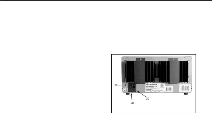
REAR PANEL CONTROLS
28.Fuse
29.Power Cord
30.110/220 Line Voltage Conversion Switch
Fig. 2. Rear Panel Controls.
13

OPERATING INSTRUCTIONS
SAFETY PRECAUTIONS
CAUTION
Avoid contacting the heat sink at the rear of the power supply. When the unit is providing large amounts of current at any or all of its outputs, the heat sink can become very hot. Contacting the heat sink when it is hot could result in skin burns or damage to the equipment in contact with them.
Use only a polarized 3-wire AC outlet. This assures that the power supply chassis, case, and ground terminal are connected to a good earth ground and reduces danger from electrical shock.
There may be great danger of electrical shock if the power supply output is connected to an external high voltage. Some equipment being powered may contain high voltage and present a shock hazard. Observe caution. If the power supply output is floated (referenced to a voltage rather than earth ground) turn off the power supply and the equipment under test when making connections. Never float the power supply to a potential greater than 100 volts peak with respect to earth ground.
EQUIPMENT PRECAUTIONS
Avoid using the power supply in ambient temperatures above +40° C. Always allow sufficient air space around the heat sink at the rear of the power supply for effective radiation to prevent internal heat build-up.
Although the power supply is protected against reverse polarity damage, the circuit being powered may not include such protection. Always carefully observe polarity; incorrect polarity may damage the equipment under test.
Do not exceed the voltage rating of the circuit being powered. Many transistors and integrated circuits will not withstand voltage of 30 volts.
There is no need to worry about voltage spikes or overshoot damaging the equipment under test. The voltage between the output terminals of the power supply never exceeds the preset value as the POWER switch is turned on or off.
INDEPENDENT USE OF “A” OR “B” SUPPLY
The “A” and “B” supplies each provide a 0-to-30 volt output at up to 2.0 amps. This procedure covers the use of the “A” and “B” supplies only when they are used independently from one another. When used in the INDEPendent operating mode, the operating controls of the two power supplies are completely independent and either supply can be used individually or both can be used simultaneously. Basic operation is covered here. Several variations are covered in the APPLICATIONS section of this manual.
14

OPERATING INSTRUCTIONS
Hook-up
1.Disengage the INDEP/TRACK mode switch so that the power supply is in the INDEPendent operating mode.
2.Turn off the power supply and the equipment to be powered during hook-up.
3.Connect the positive polarity of the device being powered to the red (+) terminal of the power supply.
4.Connect the negative polarity of the device being powered to the black (-) terminal of the power supply.
5.Fig. 3 illustrates the grounding possibilities when used in the INDEPendent mode.
a.If the negative polarity of the equipment or circuit being powered is also the chassis or common, it may be grounded to earth by strapping the black (-) terminal to the green ( ) terminal as shown in Fig. 3A.
b.Similarly, the positive polarity can be grounded by strapping the red (+) terminal to the green ( ) terminal as shown in Fig. 3B.
c.If an earth ground reference is not required, the configuration of Fig. 3C may be used. The scheme in Fig. 3C should also be used where it is not known whether the chassis is common with either the positive or negative polarity.
d.If the chassis or common of the equipment being powered is separate from both the positive and negative polarity power inputs, use the connection shown in Fig. 3D.
6.Observe proper polarity. If the circuit being powered is not equipped with reverse polarity protection, damage to the circuit can result from reverse polarity. Use color coded hook-up leads, for convenience in identifying polarity, red for (+) and black for (-).
7.Make sure that the hook-up leads offer sufficient current capability and low resistance between the power supply and the circuits being powered.
15
 Loading...