


 Loading...
Model 878B, 879B
Dual Display LCR
METER
INSTRUCTION MANUAL
Safety Summary
The following safety precautions apply to both operating and maintenance personnel and must be observed during all phases of operation, service, and repair of this instrument.
DO NOT OPERATE IN AN EXPLOSIVE
ATMOSPHERE
Do not operate the instrument in the presence of flammable gases or fumes. Operation of any electrical instrument in such an environment constitutes a definite safety hazard.
KEEP AWAY FROM LIVE CIRCUITS
Instrument covers must not be removed by operating personnel. Component replacement and internal adjustments must be made by qualified maintenance personnel.
DO NOT SUBSTITUTE PARTS OR MODIFY THE INSTRUMENT
Do not install substitute parts or perform any unauthorized modifications to this instrument. Return the instrument to B&K Precision for
1
service and repair to ensure that safety features are maintained.
WARNINGS AND CAUTIONS
WARNING and CAUTION statements, such as the following examples, denote a hazard and appear throughout this manual. Follow all instructions contained in these statements.
A WARNING statement calls attention to an operating procedure, practice, or condition, which, if not followed correctly, could result in injury or death to personnel.
A CAUTION statement calls attention to an operating procedure, practice, or condition, which, if not followed correctly, could result in damage to or destruction of part or all of the product.
Safety Guidelines
To ensure that you use this device safely, follow the safety guidelines listed below:
2
This meter is for indoor use, altitude up to 2,000 m.
The warnings and precautions should be read and well understood before the instrument is used.
When measuring in-circuit components, first de-energize the circuits before connecting to the test leads.
Discharge capacitor before testing.
The meter is safety-certified in compliance with EN61010 (IEC 1010-1) Installation Category II (CAT. II) 50 V, Pollution Degree 2 environment.
Use the meter only as specified in this manual. Otherwise, the protection provided by the meter may be impaired.
The power for the meter is supplied with a single standard 9V battery. But also a line operation is possible using a 12V AC to DC adaptor. If a power adaptor is selected, please be sure it fulfills the safety requirements of a relevant IEC standard.
3
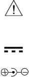
Safety Symbols
This symbol is a warning and indicates that the user should refer to the operating instructions located in the manual.
DC Current
Indicates inside pin is positive (+), outside is negative (-)
Compliance Statements
Disposal of Old Electrical & Electronic Equipment (Applicable in the European
Union and other European countries with separate collection systems)
4

This product is subject to Directive 2002/96/EC of the European Parliament and the Council of the European Union on waste electrical and electronic equipment (WEEE) , and in jurisdictions adopting that Directive, is marked as being put on the market after August 13, 2005, and should not be disposed of as unsorted municipal waste. Please utilize your local WEEE collection
facilities in the disposition of this product and otherwise observe all applicable requirements.
5
Environmental Conditions
Operating Environment |
0 |
°C to 40 °C |
|
Storage Humidity |
0 |
– 80% R.H. |
|
Storage Environment |
-20 °C to +50 |
°C |
|
Pollution degree |
Pollution degree 2 |
||
6
TABLE OF CONTENTS |
|
Safety Summary........................................................ |
1 |
Safety Guidelines ...................................................... |
2 |
Compliance Statements ........................................... |
4 |
INTRODUCTION....................................................... |
10 |
PACKAGE CONTENTS ........................................... |
11 |
FRONT PANEL OVERVIEW .................................... |
12 |
Front Panel Display Descriptions.................................. |
13 |
Front Panel Buttons ...................................................... |
14 |
LCD DISPLAY OVERVIEW...................................... |
16 |
LCD Display Descriptions ............................................. |
16 |
Special Display Indicators............................................. |
18 |
POWERING INSTRUMENT ..................................... |
19 |
Installing Battery ........................................................... |
19 |
Connecting External Power Source .............................. |
21 |
Low Battery Indication .................................................. |
23 |
Backlit Display (model 879B only) ................................ |
24 |
OPERATION INSTRUCTIONS................................. |
26 |
Data Hold...................................................................... |
26 |
Static Recording ........................................................... |
26 |
7
L/C/R/Z Select Mode .................................................... |
29 |
D/Q/θ/ESR Select Mode ............................................... |
30 |
Test Frequency............................................................. |
30 |
Relative Mode............................................................... |
31 |
Tolerance...................................................................... |
33 |
Utility Menu................................................................... |
37 |
Parallel and Series Measurement Mode....................... |
48 |
Calibration..................................................................... |
49 |
USB .............................................................................. |
53 |
Automatic Fuse Detection............................................. |
53 |
QUICK START GUIDE ............................................. |
55 |
CAUTION...................................................................... |
55 |
Inductance Measurement ............................................. |
56 |
Capacitance Measurement........................................... |
58 |
Resistance Measurement ............................................. |
60 |
Impedance Measurement (Model 879B only) ............... |
61 |
REMOTE COMMUNICATION .................................. |
63 |
Connecting Instrument to PC........................................ |
63 |
USB (Virtual COM) Configuration ................................. |
65 |
USB Operation.............................................................. |
65 |
Command Protocols ..................................................... |
67 |
8
SUPPLEMENTAL INFORMATION .......................... |
80 |
Selecting Test Frequency ............................................. |
80 |
Selecting Series or Parallel Mode................................. |
82 |
Accuracy Discrepancies................................................ |
83 |
Guard Terminal............................................................. |
85 |
SPECIFICATIONS.................................................... |
87 |
General Specifications.................................................. |
88 |
Accuracy Specifications................................................ |
89 |
MAINTENANCE........................................................ |
95 |
Service.......................................................................... |
95 |
Cleaning........................................................................ |
95 |
SERVICE INFORMATION........................................ |
97 |
LIMITED WARRANTY.............................................. |
98 |
9
INTRODUCTION
B&K Precision’s 878B and 879B 40,000-count L/C/R hand-held meter is designed ideally for measuring inductance, capacitance and resistance components. Simple to operate, the instrument not only takes absolute parallel mode measurements, but also series mode measurement. The meter provides direct and accurate measurements with selectable testing frequencies.
Front panel push buttons maximize the convenience of function and feature selection such as data hold, maximum, minimum and average record mode, relative mode, tolerance sorting mode, frequency and L/C/R selection.
The test data can be transferred to PC through a Mini USB connection, great for applications that require data logging
A tilt stand provides position flexibility for viewing and operating the meter. The over-molding rubber case protects the meter for better durability. Additionally, top rubber visor molding above the screen is designed to prevent scratches on the display when meter is positioned upside down.
10
A single 9V battery or the included DC 12V power adaptor (model 879B only) can be used to power the meter. This gives user flexibility for portable or benchtop use.
PACKAGE CONTENTS
Each 878B and 879B LCR meters are shipped with the following contents.
•878B or 879B LCR meter
•Instruction Manual
•Mini USB Interface Cable
•Red & Black Banana to Alligator Test Leads
•9V Battery
•*AC Adapter (model 879B only)
*This can be purchased as an optional accessory for model 878B.
Please locate them from the original packaging to ensure nothing is missing. If in the case that an item is missing, please contact B&K Precision immediately.
11

FRONT PANEL OVERVIEW
LCR Meter |
|
|
879B |
|
LCRZ REL ESR |
deg |
|||
MAX AVGMIN |
¦ ÈQ |
|||
TOL AUTO DH |
D |
% |
||
1%5%10%20% |
|
kHz |
||
@OFF |
|
|
PAL |
|
|
|
SER |
||
1 |
|
|
n¦ HÌ |
|
|
|
¦ |
Ì |
|
|
|
|
pn |
F |
|
|
|
Mk |
|
|
|
|
RMT |
|
2 |
|
|
R |
|
POWER |
|
USB |
HOLD |
|
3 |
|
|
REC |
|
|
|
|
|
|
7
8
4
5
6
D/Q/ |
FREQ |
UTIL |
|
/ESR |
|
9 |
|
|
|
||
|
|
|
|
L/C/R/Z |
TOL |
REL |
10 |
P S |
|
CAL |
13 |
11 |
! |
12 |
+ |
- |
|
|
Figure 1 - Front Panel Display (model 879B shown)
12
Front Panel Display Descriptions
1.LCD Display
2.Power ON/OFF Button
3.USB Communication / *Back light button
4.Secondary Display mode (for dissipation factor(D), quality factor (Q), *phase angle (θ),
*equivalent series resistance (ESR) measurement) selection button
5.Primary Display mode (for inductance, capacitance, resistance, and *impedance measurements) / Parallel or Series measurement method selection button
6.Tolerance mode / Utility down arrow selection button
7.Hold Display mode / Record mode selection button
8.Utility menu button
9.Test Frequency / Utility up arrow selection button
10.Relative mode / Calibration mode selection button
11.12V DC adapter input (use with an external power adapter (rated 12VDC, 150mA, 4mm power plug))
Note: Use with included power adapter only. Use with improper power adapters may damage instrument.
13
WARNING: Before connecting an external power adapter, please check the battery compartment in the rear side of the unit. If a battery is installed, be sure that the polarity matches the (+) and (-) labels as indicated inside the battery compartment. If it is not installed correctly, please remove the battery and install it with correct matching polarity as indicated in the compartment. See “Installing Battery” section for details. DO NOT, at any time, connect an external power adapter when a battery is installed incorrectly. Doing so will damage the instrument and void its warranty.
12.Input sockets (banana jack inputs) and terminals for positive, negative, and guard (see “Guard Terminal” in “SUPPLEMENTAL INFORMATION” section for details)
13.Standard mini USB port (for remote controllability)
*For model 879B only. Not included on model 878B.
Front Panel Buttons
All front panel buttons have specific colored labels on them. They are all marked in white, blue, or yellow
14
color. Each color has a specific representation, as described below:
White – With the exception of the  button, all white colored labels represent the primary function of that button; meaning that function will be set or configured upon pressing it.
Blue – Some of the buttons have a blue label underneath a white label. This means the function indicated by the blue label will be set or configured if that button is pressed and hold down for 2 seconds.
Yellow – There are total of 3 buttons with yellow labels. They are 

 . These functions are exclusively for use when entering UTIL menu only. See “Utility Menu” section for details.
15
LCD DISPLAY OVERVIEW
2 |
3 |
4 |
5 |
6 7 |
8 |
9 |
10 |
11 |
1 |
|
|
|
|
|
|
|
12 |
|
LCRZ REL ESR |
|
|
|
13 |
|||
|
|
|
|
|
||||
|
|
|
|
deg |
|
|||
29 |
|
MAX AVGMIN ¦ ÈQ |
|
|
14 |
|||
|
TOL AUTO DH |
D |
|
|
% |
|||
|
|
1%5%10%20% |
|
|
|
kHz |
15 |
|
28 |
|
|
|
|
|
|
PAL |
|
|
@OFF |
|
|
|
|
16 |
||
|
|
|
|
|
|
SER |
||
27 |
|
|
|
|
|
|
n¦ HÌ |
|
|
|
|
|
|
|
pn¦ FÌ |
17 |
|
|
|
|
|
|
|
|
Mk |
|
|
|
|
|
|
|
|
RMT |
18 |
|
|
|
|
|
|
|
|
|
26 |
|
25 24 |
23 22 |
21 |
20 |
19 |
||
Figure 2 - LCD Indicator Display
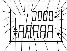
LCD Display Descriptions
1.LCRZ – Primary display function indicator (*Z display)
2.MAX – Maximum reading indicator
3.AVG – Average reading indicator
4.MIN – Minimum reading indicator
5.REL – Relative mode indicator
16

6.Θ – *Phase angle indicator for secondary display
7.Q – Quality factor indicator
8.ESR – *Equivalent series resistance indicator
9. – Secondary display
10. – Beeper tone indicator for tolerance mode
11.deg – *Phase angle degree indicator
12.Ω – *ESR(ohm) units indicator
13.% - Tolerance percentage indicator
14.kHz – Frequency units indicator
15.PAL – Parallel mode indicator
16.SER – Series mode indicator
17. – Inductance units (Henry) indicator
18. – Capacitance units (Farad) indicator
19.MkΩ – Resistance units (Ohm) indicator
20.RMT – Remote mode indicator
21. – Primary display
22.D – Dissipation factor indicator
23.DH – Data hold indicator
24.AUTO – Auto-ranging indicator
25.TOL – Tolerance mode indicator
26. – Low battery indicator
27.@OFF – Auto power-off indicator
28.1%5%10%20% - Tolerance sorting percentage indicator
17

29. MAX AVG MIN – Recording mode indicators
*For model 879B only. Not included on model 878B.
Special Display Indicators
Indicates short connectors
Indicates open connectors
Error indication
Indicates calibration mode
Indicates damaged or open fuse
AD converter error
AD converter error
18
POWERING INSTRUMENT
Before beginning to operate the instrument, a power source is necessary for it to turn on. There are two methods to power the instrument: Battery and external source.
Installing Battery
The 878B and 879B LCR meters can use a battery to provide power to the instrument so that it can be portable.
The meters use a standard 9V size battery (or NEDA 1604, JIS006P, IEC6F22 carbon-zinc or alkaline battery).
To install the battery:
1.Place the meter upside down. Open up the back-flip stand, and locate the screw that tightens the battery compartment cover as indicated in Figure 3. Use a screwdriver to unscrew and remove the cover.
19
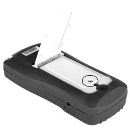
Figure 3 - Back Cover
2.Insert 9V battery into compartment. Note the positive (+) and negative (-) terminals as indicated inside the battery compartment (See Figure 4). Be sure to insert the battery with matching polarity.
20
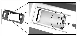
Figure 4 - Battery Compartment
3.Place the battery compartment cover piece by sliding it into the top slid first. Place screw at the bottom of the cover piece and tighten down with a screw driver.
4.Push and hold down the  button for 2 seconds to turn on the instrument.
Connecting External Power Source
The 878B and 879B can also be powered using an external AC adapter. The model 879B comes with this adapter included in the package, while it is optional for model 878B.
21
For external power, use AC adapter rated for output 12VDC, 150mA, with a standard 4mm connector only.
WARNING: Use of incorrect adapters may damage the instrument. Please use B&K Precision’s adapter only.
To connect the adapter, do the following:
1.If a battery is installed, please check the battery compartment again that the polarity of the battery matches the polarity as indicated by the labels inside the compartment. If it is not, please remove and insert the battery with matching polarity. If a battery is not installed, continue to the next step.
WARNING: DO NOT, at any time, connect an external power adapter when a battery is installed incorrectly (reverse polarity or non-matching polarity to indicator of battery compartment). Doing so will damage the instrument and void its warranty.
2.Connect the AC adapter connector into the right side panel of the instrument. See Figure 5 below.
22
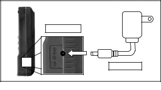
3.Now, connect the AC Adapter socket into an electrical outlet.
4.Push and hold down the  button for 2 seconds to turn on the instrument.
12VDC Input |
AC Adapter |
Figure 5 - Connecting AC Adapter to Meter |
Note: The meter can be operated with a battery installed while an AC adapter is plugged in at the same time (As long as the battery is inserted properly with correct polarity). In this event, the meter will automatically switch to consume power from the AC adapter instead of the battery to preserve battery life.
Low Battery Indication
The LCR meter has a low battery indicator to notify the user when to replace battery. When the display
23
starts flashing the  indicator, the battery voltage is below normal working voltage. In this case, accuracy of the meter will also decrease. It is recommended that the battery be replaced as soon as possible before continuing operation. See “Installing Battery” for instructions.
Backlit Display (model 879B only)
Model 879B LCR meter has a backlit display that allows you to see the LCD display in dark conditions.
To turn on the back light, press and hold down  button for 2 seconds. Back light will turn on and brighten the LCD display.
To turn off the back light at any time, press and hold
down  button for 2 seconds again. Back light will turn off and return to normal display.
When Using Battery Power
When the meter is powered using 9V battery, the back
light display will turn on upon holding down the  button for 2 seconds. It will stay at maximum
24
brightness for 15 seconds. After another 15 seconds (30 seconds total from the time of turning on), the back light will automatically turn off to conserve battery power.
When Using External Power
When the meter is powered using an external AC adapter, the back light display will turn on upon
holding down the  button for 2 seconds. It will stay at maximum brightness continuously until the
user presses and holds down the  button for 2 seconds again.
Note: If a battery is installed while using an AC adapter simultaneously, unplugging the AC adapter will automatically turn off the back light after it has been lit for 30 seconds.
25
OPERATION INSTRUCTIONS
Data Hold
The data hold function allows the user to freeze the display when pressed, holding the measured value until data hold is turned off.
Turn On Data Hold
To use data hold, press the  button once. The “DH” indicator will display on the screen when data hold is active.
Turn Off Data Hold
To disable the data hold, press  again. The “DH” indicator will disappear on the screen, and meter will remain in normal operation mode.
Note: Changing the primary function, secondary function, or test frequency will automatically turn off the data hold.
Static Recording
This mode is used for recording maximum, minimum, and average values. It is often useful for testing the range of values in which a component is expected to fall within upon measurement.
26
Enable Static Recording
Press and hold down the  button for two seconds to enter the static recording mode. The display should indicate “MAX AVG MIN” simultaneously. This indicates the meter is in static recording mode and recording is performed immediately.
Using Static Recording
There are four different modes that can be selected in static recording. They are indicated by the descriptions below. These modes can be changed
with each  button press. Per each press of the
 button, the modes will change and repeat in the following order:
Recording Mode  Maximum Mode
  Minimum
Mode  Average Mode
Recording Mode
This is the default mode when first enabling static recording. In this mode, the screen will display “MAX AVG MIN” indicator. At this point, the meter will start making recordings based on measured values from
27
the input sockets or terminals. As recording is performed, maximum, minimum, and average values will be stored after a brief moment. A beep tone will sound once a recording has been stored.
Note: Subsequent beep tones may occur in this mode if there are new values that are recorded. For example, if a new maximum is detected, it will beep once again to indicate that the new value has been stored. Any previously stored values will be overwritten with the new recorded values.
Maximum Mode
In this mode, the “MAX” indicator will be shown on display. This indicates that the value in the primary display represents the recorded maximum value.
Minimum Mode
In this mode, the “MIN” indicator will be shown on display. This indicates that the value in the primary display represents the recorded minimum value.
Average Mode
In this mode, the “AVG” indicator will be shown on display. This indicates that the value in the primary display represents the recorded average value. This average value is obtained by taking the maximum and minimum recorded values and taking the average of the two values.
28
Loading...