


 Loading...
B&K Precision 9120A, 9121A, 9122A, 9123A, 9124 Instruction Manual
...Model: 9120A, 9121A, 9122A, 9123A, 9124, 9150, 9151, 9152, 9153
Single Output Programmable DC Power
Supply
USER MANUAL

Safety information
Please review the following safety precautions before operating our equipment.
General information
The following safety precautions should be observed before using this product and any associated instrumentations.
This product is intended for use by qualified personnel who recognize shock hazards and are familiar with the safety precautions required to avoid possible injury. Read and follow all installation, operation, and maintenance information carefully before using the product. Refer to this manual for complete product specifications.
If the product is used in a manner not specified, the protection provided by the product may be impaired.
Before performing any maintenance, disconnect the line cord and all test cables.
Protection from electric shock
Operators of this instrument must be protected from electric shock at all times. The responsible body must ensure that operators are prevented access and/or insulated from every connection point. In some cases, connections must be exposed to potential human contact.
Under these circumstances personnel must be trained to protect themselves from the risk of electric shock. If the circuit is capable of operating at or above 1000 volts, no conductive part of the circuit may be exposed.
Definition of users
Responsible body is the individual or group responsible for the use and maintenance of equipment is operated within its specifications and operating limits, and for ensuring that operators are adequately trained.
This product should only be used as intended. Users must be trained in electrical safety procedures and proper use of the instrument. Users must be protected from electric shock and contact with hazardous live circuits. Service is only to be performed by qualified service personnel.
Safety symbols and terms
Connect to safety earth ground using the wire recommended in the user manual.
This symbol on an instrument indicates that the user should refer to the operating instructions located in the manual.
Certification
We certify that this product met its published specifications at time of shipment from the factory.
2
|
TABLE OF CONTENTS |
|
1. Introduction............................................................................................................ |
4 |
|
|
Description ............................................................................................................................................... |
4 |
|
Features .................................................................................................................................................... |
4 |
2. Quick Reference..................................................................................................... |
5 |
|
2.1 The Front Panel .......................................................................................................................................... |
5 |
|
2.2 The Rear Panel ......................................................................................................................................... |
6 |
|
2.3 |
Preliminary Checkout................................................................................................................................. |
7 |
|
1. Check the list of supplied items............................................................................................................ |
7 |
|
2. Connect the power cord and turn on the power supply ........................................................................ |
7 |
|
3. Checkout Procedure ............................................................................................................................. |
7 |
1.4 |
Output Verification ..................................................................................................................................... |
8 |
|
Voltage Output Check............................................................................................................................... |
8 |
|
Current Output Check .............................................................................................................................. |
9 |
1.5 |
If the power supply does not turn On ......................................................................................................... |
9 |
|
1.5.1 Fuse Replacement............................................................................................................................ |
9 |
1.6 Adjusting the Carrying Handle................................................................................................................. |
10 |
|
1.7 |
Rack Mounting the Instrument................................................................................................................. |
11 |
3. Front-panel Operation ........................................................................................ |
12 |
|
3.1 |
Front Panel Keys ...................................................................................................................................... |
12 |
|
Numerical Keys/Secondary Shift Functions........................................................................................... |
13 |
|
Shift Functions ....................................................................................................................................... |
13 |
|
Primary Function Keys........................................................................................................................... |
13 |
|
Up/Down and Entry key......................................................................................................................... |
13 |
3.2 |
Front-panel Operation Overview.............................................................................................................. |
14 |
3.3 |
Setting the Voltage.................................................................................................................................... |
14 |
3.4 |
Setting the Current.................................................................................................................................... |
14 |
3.5 |
Save and Recall Operation ....................................................................................................................... |
14 |
3.6 |
Menu Operation........................................................................................................................................ |
15 |
|
3.6.1 Menu Description.......................................................................................................................... |
15 |
|
3.6.2 Menu Function .............................................................................................................................. |
17 |
3.7 |
Output Operation...................................................................................................................................... |
22 |
3.8 |
Remote Sense and digital port functions.................................................................................................. |
22 |
3.9 |
Digital Volt Meter (DVM)........................................................................................................................ |
23 |
3.10 Milliohm Meter ...................................................................................................................................... |
24 |
|
4. Remote Operation................................................................................................ |
24 |
|
4.1 |
Serial adapter cables................................................................................................................................. |
25 |
4.2 |
Communication between Power Supply and PC...................................................................................... |
26 |
4.3 SCPI Command Overview ....................................................................................................................... |
28 |
|
|
Common IEEE488.2 Commands ........................................................................................................... |
28 |
|
Essential SCPI Commands..................................................................................................................... |
28 |
|
Port Configuration Commands............................................................................................................... |
30 |
|
Trigger Command .................................................................................................................................. |
30 |
|
SCPI Condition Register ........................................................................................................................ |
30 |
4.4 |
SCPI Command Description .................................................................................................................... |
32 |
|
Common IEEE488.2 Commands ........................................................................................................... |
32 |
|
Essential SCPI Commands..................................................................................................................... |
34 |
|
Output Commands.................................................................................................................................. |
37 |
|
List File Commands ............................................................................................................................... |
38 |
|
Interface Configuration Commands ....................................................................................................... |
42 |
|
Trigger commands.................................................................................................................................. |
43 |
|
Calibration commands............................................................................................................................ |
44 |
5. Specifications........................................................................................................ |
46 |
|
5.1 |
Specifications ........................................................................................................................................... |
46 |
5.2 |
Supplemental Characteristics ................................................................................................................... |
48 |
3
1. Introduction
Description
Models 9120A, 9121A, 9122A, 9123A, 9124, 9150, 9151, 9152, and 9153 are fully programmable, linear DC Power Supplies that provide you with clean and reliable power, high resolution and accuracy combined with fast transient response times and excellent temperature stability. The front panel keys and the control knob provide a convenient interface for adjusting Voltage and Current, storing and recalling operating states or enabling/disabling the output. This power supply is suitable for either bench or rack mounted operation. The 912xA is a compact, laboratory grade power supply well suited for applications in design, production or use in university labs.
Features
Very high accuracy and resolution: 0.1 mV, 0.1 mA
Low ripple and low noise
Fast settling time of <150 μs
|
5 |
1 |
digit digital voltage meter and mΩ meter |
|
2 |
||||
|
|
|
Convenient data entry via knob or numerical key pad
Over Temperature (OTP) protection
Bright and easy to read display (VFD technology)
Excellent temperature stability
Output on/off control
SCPI compatible command set. Communicate via USB, RS232 or GPIB (model 9123A only) interface
Application Software for front panel emulation and simple test sequence generation
Rack mount kit available
Closed case calibration
Remote Sense Function
Discrete Fault Indicator/Remote Inhibit (DFI/RI). Can be used to turn off power supplies simultaneously. (DFI available for models 9120A, 9121A, 9122A, 9123A, 9124 only)
List Mode: Generate, store and execute test sequences without the need for an external computer
4
2. Quick Reference
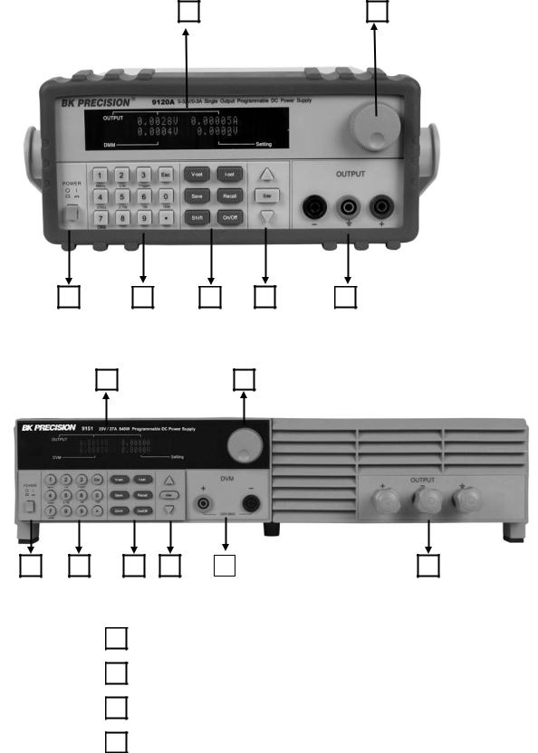
2.1 The Front Panel
For Models: 9120A, 9121A, 9122A, 9123A, 9124
1 |
2 |
3 |
4 |
5 |
6 |
7 |
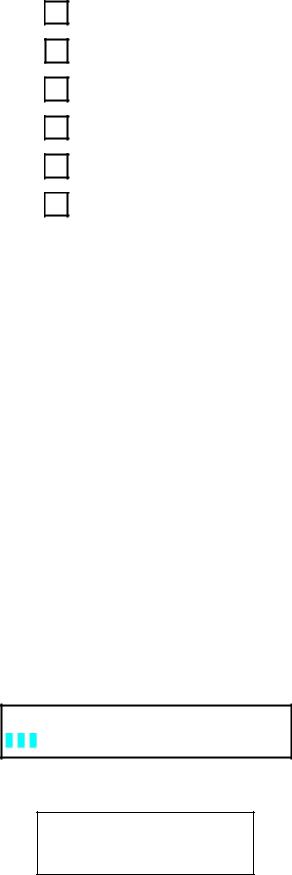
For Models: 9150, 9151, 9152, 9153 |
|
|||
1 |
|
|
2 |
|
3 |
4 |
5 |
6 |
8 |
7 |
1VFD display
2Rotary knob
3Power switch
4Numeric keys, auxiliary. functions
5

5Function keys
6Up/Down keys and “Enter” key
7Output terminals
8Digital Voltmeter terminals (For Model 9150, 9151, 9152, 9153)
2.2The Rear Panel
For Models: 9120A, 9121A, 9122A, 9123A, 9124
1 |
2 |
3 |
4 |
5 |
6 |
For Models: 9150, 9151, 9152, 9153
2
3 |
5 |
6 |
4 |
6
1
2
3
4
5
6
2.3 Preliminary Checkout
Digital Voltmeter terminals. (For models 9150, 9151, 9152, and 9153, these terminals are in the front panel)
AC power inlet and fuse compartment
Ventilation holes
Quick connect terminal for Remote sensing and digital port functions (digital I/O, DFI/RI and ext. trigger)
TTL interface connector for remote control
AC Power selection switch (110 V / 220 V)
The following steps help you verify that the power supply is ready for use.
1. Check the list of supplied items
Verify that you have received the following items with your power supply. If anything is missing, contact your authorized B&K Precision distributor.
-Power cord
-Instruction manual
-Calibration Report
-Communication cable(s)
-Software Installation disk
2. Connect the power cord and turn on the power supply
When you turn on the power supply, the front-panel display will light up briefly while the power supply performs its power-on self-test. All the VFD annunciators will turn on at once. Check for any missing display segments. Refer to section 1.5 in this chapter if the power supply does not turn on.
3. Checkout Procedure
At power up, the instrument will automatically perform a self test routine. During this time, the following should be displayed:
System Test, Please wait!
followed by
0.000V 0.0000A
0.000V 0.000V
7
The first row displays the actual output voltage value and current and the state of power supply. The second row displays the voltage measured by the DVM (on left) and the Set Value for the voltage of the power supply.
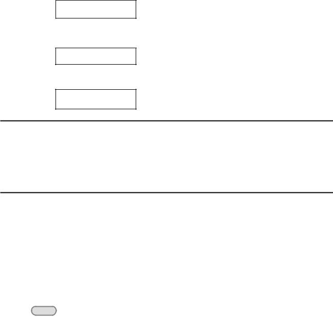
To obtain additional information about the instrument, press and hold the SHIFT button during Power Up. On the display you will see the following:
First row: |
V/A rating and DVM voltage range |
|
second row: |
Firmware version and serial number |
|
|
|
|
|
|
Sourc: XXV XA Meas: XXV |
|
|
Ver: 1.67 SN:5975002002 |
|
|
|
Press “Esc” to exit the display.
In case the self test routine is not successful, you may see one of the following:
If the EEPROM was damaged or the latest operation data is lost, the VFD will display:
ERR EEPROM
If the calibration data stored in the EEPROM is lost, the VFD will display
ERROR CAL
If the latest operating state of the power supply in EEPROM is lost, the VFD will display:
Error Config Data
 Warning: The power supply is shipped from the factory with a power-line cord that has a plug appropriate for your location. Your power supply is equipped with a 3-wire grounding type power cord; the third conductor being the ground. The power supply is grounded only when the power-line cord is plugged into an appropriate receptacle. Do not operate your power supply without adequate cabinet ground connection.
1.4 Output Verification
The following procedures verify that the power supply outputs the correct voltage and current levels and properly responds to entries from the front panel.
Voltage Output Check
The following steps verify basic voltage functions without load.
1)Turn on the power supply.
2)Enable the outputs
Press the Out on/off key. Notice the CV annunciator turning on.
8

3) Set the voltage value
Set a different voltage value. Make sure that the set value and output value are the same. Also check if the output current value is zero or close to zero A.
4) Ensure that the voltage can be adjusted from zero to the maximum rated value.
Current Output Check
The following steps check the basic current functionality by shorting the power supply’s output.
1) |
Turn on the power supply. |
2) |
Disable the output by pressing the Out on/off . The ON annunciator is turned off. |
3)Connect a short across the (+) and (-) output terminals with an insulated test lead. Use a wire size sufficient to handle the maximum current.
4)Enable the output.
5)Adjust the voltage value to 1.0 volt. Ensure that the CC annunciator is lit (power supply is in CC operation mode)
6)Adjust the current value. Set a different Current value and check if the actual Current value is the same as the set Current value. Also verify that the output voltage value is nearly zero.
7)Ensure that the current can be adjusted from zero to the full rated value.
8)Turn off the power supply and remove the short wire from the output terminals.
1.5If the power supply does not turn On
Use the following steps to help resolve problems you might encounter when turning on the instrument.
1. Verify that there is AC power applied to the power supply.
Verify that the power cord is firmly plugged into the power receptacle on the rear panel of the power supply. Make sure the power outlet you are using is working properly and verify that the power supply is turned on.
2. Verify the power-line voltage setting.
Make sure the voltage selector switch is set according to the present line voltage (110 VAC or 220 VAC). Change the voltage setting if it’s not correct.
3. Verify that the correct power-line fuse is installed.
1.5.1 Fuse Replacement
Model |
Fuse Description (110 VAC) |
Fuse Description (220 VAC) |
||
9120A |
T2.5A |
250V |
T1.25A |
250V |
9121A |
T2.5A |
250V |
T1.25A |
250V |
9124 |
T2.5A |
250V |
T1.25A |
250V |
9122A |
T3.15A |
250V |
T1.5A |
250V |
9123A |
T3.15A |
250V |
T1.5A |
250V |
9150 |
T10A |
250V |
T5A |
250V |
9151 |
T10A |
250V |
T5A |
250V |
9152 |
T10A |
250V |
T5A |
250V |
9153 |
T10A |
250V |
T5A |
250V |
Replace blown fuses according to the table above.
9

1.6 Adjusting the Carrying Handle
To adjust the position, grasp the handle by the sides and pull outward. Then rotate the handle to the desired position.
Dimensions:
214.5 mm (W) x 88.2 mm (H) x 354.6 mm (D) all units in mm
For Models: 9120A, 9121A, 9122A, 9123A, 9124
10
For Models: 9150, 9151, 9152, 9153
1.7 Rack Mounting the Instrument
You can mount the power supply in a standard 19-inch rack cabinet using the IT-E151 rack mount kit.
Note: Remove the carrying handle and the two plastic ears before rack-mounting the instrument. To remove the handle, grasp the handle on the side, pull outwards and rotate it to a special position where the arrow on the handle and the arrow on the plastic ears are in opposite directions. Now you can pull the handle outwards. After removing the handle, you can remove the two plastic ears with a screw driver.
11
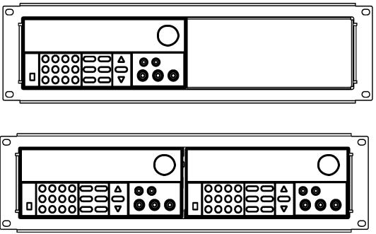
To rack mount a single instrument, order rack mount kit IT-E151
To rack mount two instruments (models 9120A, 9121A, 9122A, 9123A, 9124 only) side-by-side, order rack mount kit IT-E151, In this case you don’t need to use the front cover panel.
3. Front-panel Operation
So far we have covered the quick start chapter which briefly introduced the front panel operation and how to check basic voltage and current functionality. This chapter describes in detail how to operate the instrument manually via the front-panel keys.
This chapter is divided into the following sections:
Front-Panel Operation Overview
Setting the Voltage
Setting the Current
Save/Recall Operation
Menu Operation
On/Off Operation
Remote Sense and digital port functions
mΩ Meter
Digital Voltage Meter
3.1Front Panel Keys
12
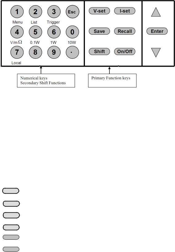
Numerical Keys/Secondary Shift Functions
Shift Functions
V/mΩ: Toggle between DVM and mΩ Meter mode
0.1 W: |
Set the range of the mΩ Meter to 0.1 W |
||
1 W: |
Set the range of the mΩ Meter to 1 W |
||
10 W: |
Set the range of the mΩ Meter to 10 W |
||
Menu |
Set the parameters of the power Supply |
||
List |
Generate programs in List Mode |
||
Trigger |
Generate a single trigger pulse (when configured for Immediate mode) |
||
Local |
Enable front panel operation when in remote mode |
||
0 – 9 |
Numerical keys for direct entry of values |
||
Primary Function Keys |
|||
|
|
|
|
|
|
V-set |
Set the voltage value |
|
|
|
|
|
|
I-set |
Set the current value |
|
|
|
|
|
|
|
|
|
|
Save |
Save the current operating data to internal memory |
|
|
|
|
|
|
|
|
|
|
Recall |
Recall operating data from internal memory |
|
|
|
|
|
|
|
|
|
On/Off |
Set the output state of the power supply |
|
|
|
|
|
|
|
Shift |
Use to access secondary functions |
|
|
|
|
Up/Down and Entry key
▲ Up key
13
▼ Down key
Enter: Press to confirm numerical entries
3.2 Front-panel Operation Overview
1)The power supply at shipment is preconfigured for front-panel operation. At power-on, the power supply will automatically start up in front panel operation mode.
2)When the power supply is in remote operation mode, the front-panel is disabled. You can revert to Local mode, by pressing the Local button or by sending the appropriate SCPI command. Toggling between front-panel and remote operation modes will not result in any change of the output parameters.
3)The output of the power supply can be enabled or disabled from the front panel by pressing
the Out on/off key. When the output is on, the CV or CC annunciator will turn on.
4)The VFD annunciators display the present operating status of the power supply. At power up, the following is displayed: The top row shows the actual output voltage and output current value and the state of the power supply. The second line shows the voltage value as measured by the DVM and the Set value of the Voltage. The bottom right field is also used to display the Current Set Value, the Menu parameters and the Ohm meter range.
3.3 Setting the Voltage
The Voltage can be adjusted from 0V to the maximum rated voltage of each model. There are 2 ways to set the constant voltage value.
Solution1
Press the ▲ and ▼ keys or the knob to change the value of the least significant digit
Solution2:
1. Press |
V-set |
|
|
|
|
2. Use the numeric keys 0 to 9 |
and confirm your entry by pressing Enter |
|
3.4 Setting the Current
The Current output is adjustable from 0A to the maximum current value of each model.
1. Press
2. Enter a numerical value or use the ▲and ▼keys to change the current value 3. Press Enter to confirm the value
3.5 Save and Recall Operation
You can store up to 50 different operating states in memory locations 1 through 50. Each operating state includes a constant voltage value, constant current value, maximum output voltage value and voltage step value.
To save a setting:
Set the desired Voltage and Current value
Press the save Save key. Use the knob to scroll to one of the memory locations 1 – 50. Press ENTER
14

to assign and store the current settings to the selected memory location To recall a setting:
Press the Recall key. Use the knob to scroll to the memory location where the settings you want to recall are stored. Press ENTER to recall and activate those settings
You can also use the SCPI command:*SAV *RCL to save and recall respectively.
3.6 Menu Operation
3.6.1 Menu Description
Press Shift :Menu to enter menu mode. The menu parameters will be displayed in the bottom right field of the display. Use the ▲ and ▼ keys to scroll through the menu list and press ENTER to select a menu and view the
parameters. Press ESC to return to the higher level menu and to return to the main operating mode.
MENU |
|
|
|
|
|
|
|
|
|
|
Config |
|
|
|
|
|
|
|
|
|
|
|
|
Config |
Init. |
|
|
Return to the factory default setup value. |
||||
|
|
Out Recall |
|
|
Set the Power ON/OFF state after power up. |
|||||
|
|
|
On |
|
|
|
“Remembers” and restores the Power ON/OFF state of the |
|||
|
|
|
|
|
|
|
power supply before power was turned off. |
|||
|
|
|
Off<Default> |
|
|
|
Disable this function. |
|||
|
|
PWR- |
ON Recall |
|
|
Recall operating parameters of power supply after power up |
||||
|
|
|
On |
|
|
|
“Remembers” and restores the operating parameters of the |
|||
|
|
|
|
|
|
|
power supply (voltage, current settings..) before power was |
|||
|
|
|
|
|
|
|
turned off. |
|||
|
|
|
Off<Default> |
|
|
|
Disable this function. |
|||
|
|
Key Sound Set |
|
|
Keypad sound setting. |
|||||
|
|
|
On<Default> |
|
|
|
Enable key sound. |
|||
|
|
|
Off |
|
|
|
Disable key sound |
|||
|
|
Knob |
Lock Set |
|
|
|
Enable/disable the rotary knob. |
|||
|
|
|
On |
|
|
|
Lock the rotary knob. |
|||
|
|
|
Off< Default > |
|
|
|
Unlock the rotary knob. |
|||
|
|
Remote |
Sense |
Setup |
|
voltage measurement Mode. |
||||
|
|
|
|
|
|
|
|
|
|
|
|
|
|
On |
|
|
|
|
The power supply will measure the input voltage at the |
||
|
|
|
|
|
|
|
|
remote sense connector. |
||
|
|
|
Off< Default > |
|
|
|
|
The power supply will measure the input voltage at the |
||
|
|
|
|
|
|
|
|
front panel connector. |
||
|
ShortCut |
Call |
Shortcut of the recall function |
|||||||
|
|
|
On |
|
|
|
|
Enable this function |
||
|
|
|
Off<Default> |
|
|
|
|
Disable this function |
||
|
|
Meter |
Rate |
Set the |
update speed of the power supply meter |
|||||
|
|
|
High |
|
|
|
|
High speed |
||
|
|
|
Low <Default> |
|
|
|
|
|
Low speed |
|
|
|
Baudrate |
Set |
|
|
|
|
|
|
|
|
|
|
Baudrate 4800 <Default> |
|
|
|||||
|
|
|
Baudrate 9600 |
|
|
|
|
|
|
|
|
|
|
Baudrate 19200 |
|
|
|
|
|
|
|
|
|
|
Baudrate 38400 |
|
|
|
|
|
|
|
|
|
Comm. |
Parity |
Configure |
the parity bit. |
|||||
15
None< Default >
Even
Odd
|
Address Set |
Set the communication address (range from 0 to 30) |
|||||||
|
|
Address= |
|
|
|
|
|
|
|
|
Port Mode |
Select |
mode of digital port |
|
|||||
|
|
|
Trigger< Def > |
|
|
|
|
|
|
|
|
|
RI/DFI |
|
Note: DFI is not available for models 9150, 9151, 9152, |
||||
|
|
|
|
|
9153 |
|
|
||
|
|
|
DIGITAL I/O |
|
Note: Digital output not available for models 9150, 9151, |
||||
|
|
|
|
|
9152, 9153 |
|
|
||
|
Trig Source |
Setting |
|
the trigger mode |
|
||||
|
|
Immediat<Def> |
|
|
|
Pressing |
Shift |
+ Trigger keys will generate a |
|
|
|
|
|
|
|
|
trigger pulse |
|
|
|
|
External |
|
|
|
Ext. Trigger signal is applied to the digital port in the rear |
|||
|
|
|
|
|
|
|
panel. |
|
|
|
|
Bus |
|
|
|
Remote command trigger mode. |
|||
|
RI Mode |
Configure the Remote Inhibit (RI) mode |
|||||||
|
|
Off< Default > |
|
|
|
Disable this function |
|
||
|
|
|
|
|
|
|
|
|
|
|
|
Latching |
|
|
|
|
|
|
|
|
|
Live |
|
|
|
|
|
|
|
|
DFI Source |
Configure |
|
the Discrete Fault Indicator (DFI) mode |
|||||
|
|
|
|
Note: |
|
|
Not used for models 9150, 9151, 9152, 9153 |
||
|
|
Off< Default > |
|
|
|
|
|
|
|
|
|
QUES |
|
|
|
Question Bit |
|
||
|
|
OPER |
|
|
|
Operation Bit |
|
||
|
|
ESB |
|
|
|
Event State Bit |
|
||
|
|
RQS |
|
|
|
Require Bit |
|
||
|
Key Lock Set |
Setting |
keypad password. |
|
|||||
|
|
|
|
Press |
|
|
Enter |
directly to disable the key lock function. |
|
|
|
|
Password= **** |
|
|
|
|
|
|
|
Exit |
|
|
|
|
|
|
|
|
System |
Set |
|
|
|
|
|
|
|
|
|
Max Volt. set |
Set the Maximum Voltage. |
|
||||||
|
|
Max= **** |
|
|
|
|
|
|
|
|
Step Volt Set |
Set the |
voltage step |
|
|||||
|
|
Step=**** |
|
|
|
|
|
|
|
|
Exit |
|
|
|
|
|
|
|
|
List Set |
|
|
Configure list files |
|
|
|
|
|
|
|
Call ListFile |
Recall list operation file. |
|
||||||
|
|
|
Recall * |
|
|
|
|
|
|
|
Edit ListFile |
Edit list |
operation file. |
|
|||||
|
|
|
Continuous |
|
|
|
|
|
|
Once
Repeat
Step
Once
Repeat
Users can allocate 4 types of memory space to save the list file.
16
Loading...