


H1000
display installation
IS-2502

Brookes & Gatehouse Ltd
Premier Way,
Abbey Park,
Romsey,
SO51 9AQ
UK
Tel: (+44) (0)1794 518448
Fax: (+44) (0)1794 518077
Global W ebsi te: www. BandG.com
© 2001 Brookes & Gatehouse Ltd
B&G USA
13191 56th Court,
Suite 106,
Clearwater,
Florida 33760
USA
Tel: (+1) 727 540 0229
Fax: (+1) 727 540 0281
B&G France
Place Bernard Moitessier,
Plateau Nautique,
17000 La Rochelle,
France
Tel: (+33) 5 46 44 01 01
Fax: (+33) 5 46 34 30 07

CE Certification:
This equipment generates, uses, and can radiate radio frequency energy and, if not installed and used in
accordance with the instruction s, may cause harmful interference to radio communications. However, th ere is no
guarantee that interference will not occur in a particular in stallation. If this equipment does cause harmfu l
interference, the user is encouraged to try to correct th e in terferen ce by relocating the equipment or connecting
the equipment to a different circuit. Consult an authorised dealer or other qu alified technician for additional help
if these remedies do not correct the problem.
This device meets requirements for CFR47 Part 15 of the FCC limits for Class B equipment.
The
h1000
navigation and radiocommunication equipment and systems .
:
: :
meets the standards set out in European Standard EN 60945: 1997 IEC 945 : 1996 for maritime
CE-Zertifizierung::::
Dieses Gerät erzeugt und verwendet HF-Energie und kann diese ausstrahlen; wenn es nicht gemäß der
Anweisungen installiert und verwendet wird, kann es störende Interferenzen mit dem Funkverkehr verursachen.
Allerdings wird nicht gewährleistet, dass es bei eine r bestimmten Installation keine Interferenzen geben wird.
Wenn dieses Gerät Störungen verursacht, sollte der Benutzer versuchen, die Störungen zu beheben, indem er das
Gerät anders aufstellt oder an einen anderen Stromkreis anschließt. Wenden Sie sich für zu sätzliche Hilfe an den
Vertragshändler oder einen Fachmann, wenn das Problem durch diese Maßnahmen nicht behoben werden kann.
Dieses Gerät entspricht den Anforderungen für CFR47 Teil 15 der FCC-Begrenzungen für Geräte der Klasse B.
Der
h1000
und Funkkommunikationsgeräte und -systeme.
erfüllt die Vorschriften der Europäischen Norm EN 60945:1997 IEC 945:1996 für maritime Navigations-
Certificación CE:
Este equipo genera, utiliza y puede radiar energía de radiofrecuencias y si no se instala y utiliza de acuerdo con
las instrucciones, puede causar interferencias dañinas con las comunicaciones de radio. Sin embargo, no hay
ninguna garantía de que no ocurran interferencias en una instalación particular. Si este equipo causa
interferencias, se aconseja al usuario que in ten te elim in arlas cambiando de sitio el equipo o conectándolo a un
circuito diferente. Si estas acciones no corrigen el problema, consulte a un concesionario autorizado u otro
técnico calificado para que le ayude.
Este dispositivo cumple con los requ isitos de CFR47 Parte 15 de los límites F CC para equ ipo de Clase B.
El
h1000
sistemas de navegación y radio comun icaciones marítimas.
:
: :
satisface las normas establecidas en la Norma Europea EN 60945: 1997 IEC 945 : 1996 para equipo y

Certification CE :
Cet équipement émet et utilise une fréquence qui peut rayonner de l’énergie et, si son installation et son
utilisation ne sont pas conformes aux instructions, il peut être la cause de parasites nuisibles aux
communications radio. Il n’y a cependant aucune garantie que des parasites ne se produiront pas dans une
installation spécifique. Si cet équipement est la cause de parasites nuisibles, il est conseillé à l’utilisateu r de
remédier à ces parasites en déplaçant les appareils ou en effectuant le branchement su r un circuit différent. Il
faudra consulter un agent agréé ou un autre technicien qualifié pour une aide supplémentaire si le problème
n’est pas résolu par ces interventions..
Cet appareil est conforme aux normes requises pour la certification CF R47 Part 15 des limites FCC aux USA pour
les équipements de Classe B.
Le
h1000
est conforme aux normes définies par la Norme Européenne EN 60945: 1997 IEC 945 : 1996 pour la
navigation maritime et les équipements et systèmes de télécommunications .
Marcatura CE:
Questo equipaggiamento genera, utilizza e può irradiare l’energia della frequenza radio e, se non viene installato
e usato in base alle istruzioni, può causare interferenze pericolose alle comunicazioni radio. Non vi è neppure
nessuna garanzia che una determinata installazione non sia soggetta a interferenze. Se questo apparecchio
causa interferenze nocive, incoraggiamo l’utente a cercare di correggere tali interferenze riposizionan d o o
collegando l’equipaggiamento a un circuito diverso. Rivolgersi a un concessionario autorizzato o a un tecnico
opportunamente addestrato per ulteriore assistenza se questi rimedi non correggono da soli il problema.
Questo dispositivo soddisfa i requisiti della normativa CFR47 Parte 15 dei Limiti FCC per l’equipaggiam en to
Classe B.
Il modello
h1000
equipaggiamento e sistemi per la navigazione marittima e le radiocomu n icazioni.
soddisfa gli standard esposti nella normativa europea EN 60945: 1997 IEC 945: 1996 per

features
The
h1000
is a fully functional unit which can be used either as a stand-alone device or integrated into an in strument
system.
trademark
All rights reserved. No part of this manual may be reproduced or transmitted in any form or by any means including
photocopying and recording, without the express written permission of B&G.
Information in this document is subject to change without notice. B&G reserves the right to change or improve its
products and to make changes in the content w ith ou t obligation to notify any person or organisation of such changes.
technical specifica t ions
Dimensions mm: 110mm x 110mm x 40mm
Power Supply: 12V dc nominal (10V to 16V) via FastNet
Power Consumption: 0.45W to 0.85W (dependent on lighting level)
Display: FSTN Dot-Matrix Transflective LCD
Display Resolution: 120 x 80 pixels
Operating Temp erature range: -10 to +55ºC (+14 to +130ºF)
Storage Temperature range: -25 to +70ºC (+13 to +158ºF)
Humidity: Up to 95% RH
Sealing: IP67 (with dust caps fitted)
Accessories: Flush mounting kit, mounting template,
power supply, I/O cable and protective cover
2
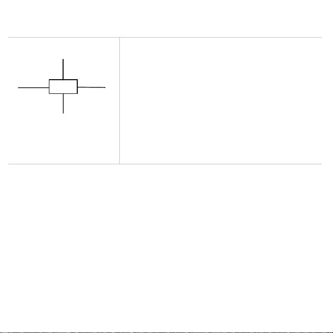
system connections
Bus cable
Bus cable Bus cable
“HUB”
12V power cable
connections
System components share data together via a common Fastnet2 databus
and are supplied with bayonet connectors for ease of in stallation. A
selection of cable lengths are available with options for straight and right
angle connectors to suit most requirements.
To prevent the occurrence of voltage drops on larger systems, the power
supply to the system should either be placed mid-way or at both ends of
the Fastnet2 databus. To connect power to the mid-point of the system, it
is recommended that the 4-Way Hub be used. The 4-Way Hub offers two
advantages. The first advantage is that it offers a convenient entry point
for power onto the system. The second advantage is that it conveniently
allows the system to be branched to reduce the overall length of the
system. The correct selection of Fastnet2 cable will negate the need for
any plugs to be removed from the system and ensure years of faultless
operation.
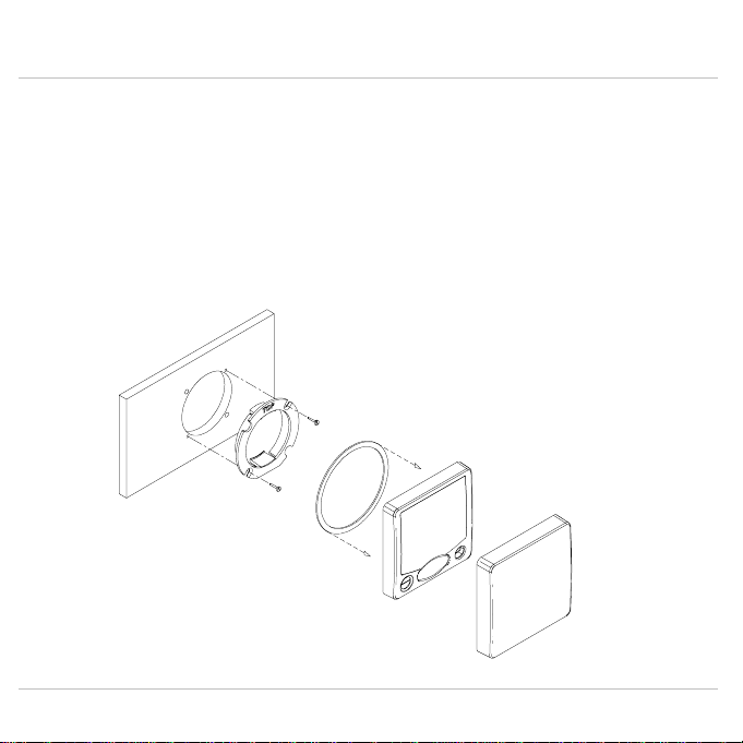
installation
panel mounting
Ensure there is sufficient room behind the panel to ac commodate the fixings and connections, and usin g th e
template supplied, cut a hole in the panel in the desired position.
Fix the mounting bracket into the hole using the screws supplied.
Note
Note: The sealing ring is fitted to the unit during manufacture. It’s purpose is to prevent moisture penetration and
NoteNote
reduce the effects of any vibration transmitted th rou g h th e in strument panel.
Press the
Display
Display
firmly into the mounting bracket; an audible ‘clic k’ will indicate that the case is correctly located.
DisplayDisplay
Secure the unit to the instrument panel by fitting the stud s and thumbnuts supplied.
Caution
Caution: To avoid damaging the casing, fixing studs must only be tightened ‘finger-tight’.
CautionCaution
Sealing Ring
(Fitted at Manufacture)
Protective
Mounting
Cover
Bracket
Display
Unit
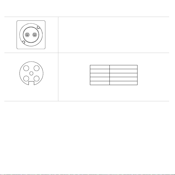
electrical connections
2 3
5
41
Front view of
male connector pins
external connections
Two FastNet² connectors are provided at the rear of the unit. These
connectors allow connection to the rest of the system for the supply of power
and data.
The table below shows pin functions.
Pin Number Signal
Pin Number Signal
Pin Number Signal Pin Number Signal
1 12V
2 Busy
3 FastNet²4 FastNet²+
5 0V
setup
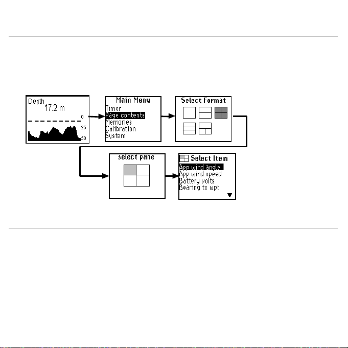
custom pages
Pressing the ENTER
Select one of the five pre-defined display layouts using the ST keys.
Once a Display layout has been s elected you can then select which inform ation is displayed in each panel. Using the
ST keys scroll through the choices and then press the ENTER
Repeat the selection process until you have made a selection for each panel then highlight OK and press the ENTER
key to save.
ENTER key from the data page will display the c on figu ration m enu, select the
ENTERENTER
ENTER key to select.
ENTERENTER
Page Contents
menu.
ENTER
ENTERENTER
setup
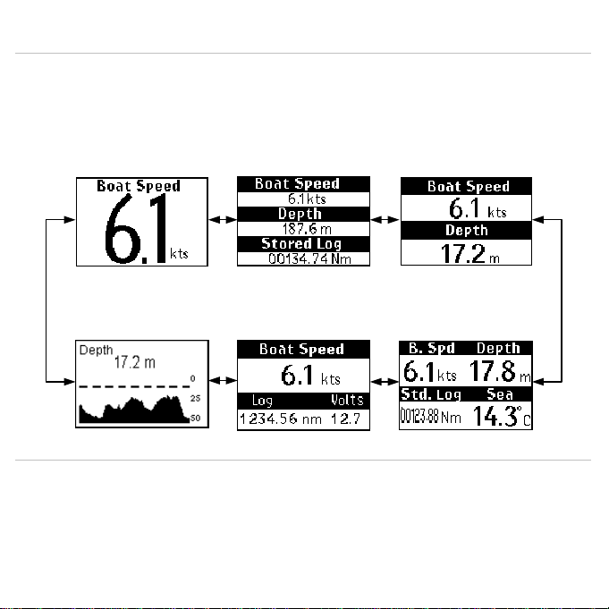
default data pages
Your new
h1000 LCD Display
over-written to suit particular requirements. Referring to Page Contents in the
items to display from the list of available options.
The flexibility of the
personal preference.
has factory Default Page formats already pre-programmed. How ever, these can be
h1000 system
allows an endless combination of display formats to su it different boat types and
h1000 User Manual
, select which
▲ ▼
▲ ▼ ▲ ▼
▲ ▼
Stored Log
▲ ▼
▲ ▼
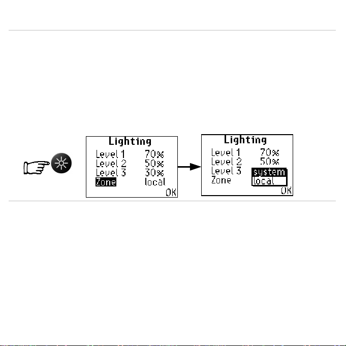
setup
light controls
The lighting level can be changed at any time by pressing the LIGHTS key. This causes the lighting level to cycle in th e
sequence HIGH MEDIUM LOW OFF and then back to HIGH.
The exact levels that correspond to these settin gs can be adjusted on the main memories lighting menu.
Display lighting levels are cont rolled b y the LIGHTS key in normal operation, but the exact level of illumination c an be
adjusted on this menu.
The levels are numbered in the order they appear when the key is used, and each level can be set in percentage
terms.
This menu page allows the lighting control to be applied either Local (this display unit only), or Zone (the entire
system).
The OK command returns the display to the m ain menu.
.
. .

system display
deutsch
 Loading...