


H5000
Operation Manual
ENGLISH
www.bandg.com

Preface
As Navico is continuously improving this product, we retain the right to make changes to the product at any time which may not be reflected in this version of the manual. Please contact your nearest distributor if you require any further assistance.
It is the owner’s sole responsibility to install and use the instrument and transducers in a manner that will not cause accidents, personal injury or property damage. The user of this product is solely responsible for observing safe boating practices.
NAVICO HOLDING AS AND ITS SUBSIDIARIES, BRANCHES AND AFFILIATES DISCLAIM ALL LIABILITY FOR ANY USE OF THIS PRODUCT IN A WAY THAT MAY CAUSE ACCIDENTS, DAMAGE OR THAT MAY VIOLATE THE LAW.
Governing Language: This statement, any instruction manuals, user guides and other information relating to the product (Documentation) may be translated to, or has been translated from, another language (Translation). In the event of any conflict between any Translation of the Documentation, the English language version of the Documentation will be the o cial version of the Documentation.
This manual represents the product as at the time of printing. Navico Holding AS and its subsidiaries, branches and a liates reserve the right to make changes to specifications without notice.
Copyright
Copyright © 2014 Navico Holding AS.
Warranty
The warranty card is supplied as a separate document. In case of any queries, refer to the brand website of your display or system:
www.bandg.com
Declarations and conformance
This equipment is intended for use in international waters as coastal sea area administered by countries of the E.U. and E.E.A.
The H5000 system complies with the following regulations:
•CE under EMC directive 2004/108/EC
•Level 2 devices of the Radio communications (Electromagnetic Compatibility) standard 2008
The relevant Declaration of conformity is available in the H5000 section on the following website: www.bandg.com
| H5000 Operation Manual |
| 1 |

Contents
5Introduction
5About this manual
7System overview
7H5000 components
8H5000 Central Processor Unit - CPU
8Webserver - Network portal
8Graphic display
9Race display
9HV Displays
10 Analog displays
10Expansion modules
11Sensor modules
11Alarm module
12H5000 Pilot Controller
13System examples
13Hydra
14Hercules
15Performance
16Autopilot minimum system requirement
16Basic System - No H5000 CPU
17Operation
17Graphic display
18Default graphic display pages
25Data page transition
25Available data pages
26Replacing a data page
27Menus
28Race timer
30Man Over Board
31HV display support
32Alarms
34 |
Damping |
34 |
Trip log |
34Log
35Race display
40 Diagnostics
43H5000 Pilot Controller
44Autopilot operation
45Autopilot modes
48 Sensor calibration
48Depth
49Boat speed
52Environment
53Masthead unit adjustment
55Heading (compass)
Contents | H5000 Operation Manual |
| 3 |
57 System setup
57 Network
59Units
60Language
60 Time
60Simulate
61Restore defaults
61 Global reset
61About
62Autopilot setup
62Source selection
62Rudder drive
64 Commissioning
67Response
68Sailing
69Steering
71Setup
73 Webserver
78 Operating variables
105Example data tables
105Polar table
106Boat speed / Heel correction table
106True wind angle correction table
106True Wind Speed correction table
106Down wind speed correction table
107Maintenance
107Basic maintenance procedures
108Winter Storage / Laying Up
4 | |
Contents | H5000 Operation Manual |

1 |
Introduction |
||
|
|
|
|
About this manual |
|||
This manual is a reference guide for operating the B&G H5000 instrument system. It assumes |
|||
that all equipment is installed correctly, and that the system is ready to use. |
|||
|
The manual assumes that the user has basic knowledge of navigation, nautical terminology |
||
|
and practices. The manual does not cover basic background information about how |
||
|
equipment such as radars, echo sounders and AIS work. |
||
|
Important text that requires special attention from the reader is emphasized as follows: |
||
|
¼ Note: Used to draw the reader’s attention to a comment or some important information. |
||
|
|
|
|
|
|
|
Warning: Used when it is necessary to warn personnel that they |
|
|
|
should proceed carefully to prevent risk of injury and/or damage to |
|
|
|
equipment/personnel. |
|
|
|
|
Introduction | H5000 Operation Manual |
| 5 |
6 | |
Introduction | H5000 Operation Manual |

2The H5000 instrument and autopilot systems combine unique sailing features with raceproven technology in a straightforward package. Developed for blue water cruisers and racing yachts alike, the range brings powerful system options to match your exacting requirements. From an ultra-fast CPU to a convenient web-browser interface access, full-color and custom displays and a dedicated autopilot controller, the H5000 system was developed to provide the best instrument and autopilot system available. The H5000 range comprises several units which network with other onboard electronics including the Zeus range of chart plotters.
The H5000 system is driven by a powerful Central Processing Unit (CPU) reaching speeds up to 50 times greater than its predecessor, with Hydra, Hercules and Performance level
software options tailored for all users from serious cruisers to professional racers. It works with B&G’s H3000 Wind, Speed, Heel and meteorological sensors for straightforward upgrades. The high resolution H5000 Graphic Display is highly intuitive and delivers information on a 5-inch bonded screen with fast, smooth display updates. The H5000 Race Display provides segmented text, numbers and target indicator for the race information you need in a glance.
The H5000 Autopilot brings the functionality and dedicated sailing algorithms of its recordbreaking predecessor , supporting the exact needs of a performance sailboat and its crew – whether short-handed cruising or solo racing. In addition, the H5000 Pilot Controller provides dedicated access to autopilot functions.
B&G’s web-browser interface lets you connect your PC or tablet to the network for setup, calibration and control of every part of your H5000 system. It utilizes a familiar web browser
interface to allow quick calibration of instruments, easy setup of displays and configuration of features. You can also access online product manuals, data backups and network diagnostics.System overview
H5000 components
•H5000 Central Processor Unit - CPU
•Webserver - Network portal
•Graphic display
•Race display
•HV displays
•Analog displays
•Expansion modules
•Sensor modules
•Alarm module
•H5000 Pilot Computer
•H5000 Pilot Controller
System overview | H5000 Operation Manual |
| 7 |
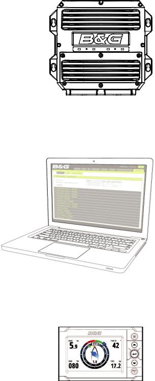
H5000 Central Processor Unit - CPU
The H5000 CPU takes sensor inputs and uses a dedicated processor to calculate and calibrate the data and distribute it to display units and external devices.
Connect a router via the ethernet port to take advantage of the webserver interface via a PC, tablet or smart-phone.
There is a USB port to upgrade the CPU with the latest software.
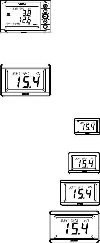
Webserver - Network portal
The browser-based configuration of the H5000 system enables advanced calibration, set-up and diagnostics. Its web-style interface can be accessed via PC, tablet or smartphone.
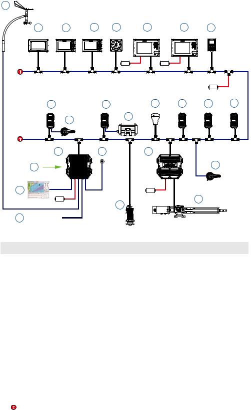
Graphic display
The H5000 Graphic Display is a 5-inch, sunlight viewable, color display. It shows sailing data in digital or graphical form.
8 | |
System overview | H5000 Operation Manual |
Race display
The H5000 Race Display is a 7 segment display, 5-inch screen designed for viewing essential data at a glance. A dedicated page key allows quick switching between stored pages displaying 2 data values on each page alongside a unique bargraph providing immediate visual indication of performance targets, countdown timer status and more.
MENU |
HV Displays
The HVision range of displays are lightweight, single-line data units incorporating B&G’s unique HV technology. HV technology ensures the maximum contrast, perfect backlighting and no possibility of condensation. HV displays are the clearest displays available.
¼ Note: There are four displays in the HV range, each with their ideal application:
10/10 HV
The 10/10 is a compact display that allows data to be positioned where it is needed, rather than where it fits. Its compact dimensions allow the 10/10 to be installed almost anywhere – typical installation areas are the base of winch pedestals, alongside hydraulic control panels, steering pedestals or as a companionway display on the smaller yacht.
20/20 HV
The latest generation of the classic 20/20 mast display. The 20/20 is the de facto standard for mast displays on yachts up to 70’ (21m). The 20/20 is also ideal for use as a cockpit, saloon or bridge display.
30/30 HV
The 30/30 is designed as a mast display for yachts in the range 60-90’ (18-27m) LOA. Providing these larger yachts with the perfect size of display. The 30/30 is also the ideal display for deck or bridge displays on super yachts.
40/40 HV
The 40/40 is the largest instrument display available. Designed specifically for mast mounting applications on super yachts, it also is the ideal display for forward beam mounting on maxi-multi hulls or as a deck or helipad display on large motor yachts.
System overview | H5000 Operation Manual |
| 9 |

Analog displays
Before a value will be shown on an analog display ensure that a sensor (source) has been selected via the CPU or Graphic Display. Go to source selection to achieve this.
The analog display backlighting is achieved by a long press of the MENU key on any of the Graphic displays.
There is a wide range of analog indicators available, all listed below.
• Apparent Wind Angle |
• Depth 200 Meters |
• True Wind Angle |
• Apparent Wind Speed |
• Depth Ft / Fathom |
• True Wind Speed |
• Boat Speed 12.5 Knot |
• Heading |
• Magnified Apparent Wind |
• Boat Speed 25 Knot |
• Rudder |
|
Expansion modules
There are two types of Expansion module, Analog and Serial. The modules act as the interface between analog sensors, serial devices and other in and outputs to and from the CPU.
The correct module must be used in conjunction with its corresponding sensors. All modules are powered from the network and can supply power to the sensors connected.
Analog
The analog module has 6 analog inputs and 2 pulse inputs. This allows the unit to act as an interface for masthead units, speed sensor, analog rate-gyros, potentiometer etc.
Serial
The serial module has 2 COM ports, each with input & output. The modules support RS232, RS422, RS485 and NMEA 0183 devices.
Modules can be located wherever is most convenient for the installer and can connect anywhere on the network.
10 | |
System overview | H5000 Operation Manual |
Sensor modules
There are two types of H5000 sensor module.
Barometric & temperature sensor
Measures the atmospheric pressure and air temperature, allowing the CPU to record atmospheric pressure changes over varying periods of time and current air temperature.
3D Motion
The Tri-Axis Motion Sensor provides accurate measurement of the heel and trim angles as well as pitch, roll and yaw rates of the yacht, allowing the CPU software to correct the wind data for errors induced by this motion.
Alarm module
The alarm module is a network audible alarm that can be positioned anywhere on the network.
H5000 Pilot Computer
The H5000 Pilot Computer links with the H5000 instrument system. The instrument system transmits sensor information over the network to the Pilot Computer. This information is processed by the Pilot Computer and sends signals to the drive system (linear ram, rotary drive or hydraulic pump) to steer the vessel on the desired heading/course.
|
|
|
|
|
|
|
|
|
|
|
|
|
|
|
|
|
|
|
|
|
|
|
|
|
|
|
|
|
|
|
|
|
|
|
|
|
|
|
|
|
|
|
|
|
|
|
|
|
|
|
|
|
|
|
|
|
|
|
|
|
|
|
|
|
|
|
|
|
|
|
|
|
|
|
|
|
|
|
|
|
|
|
|
|
|
|
|
|
|
|
|
|
|
|
|
|
|
|
|
|
|
|
|
|
|
|
|
|
|
|
|
|
|
|
|
|
|
|
|
|
|
|
|
|
|
|
|
|
|
|
|
|
|
|
|
|
|
|
|
|
|
|
|
|
|
|
|
|
|
|
|
|
|
|
|
|
|
|
|
|
|
|
|
|
|
|
|
|
|
|
|
|
|
|
|
|
|
|
|
|
|
|
|
|
|
|
|
|
|
|
|
|
|
|
|
|
|
|
|
|
|
|
|
|
|
|
|
|
|
|
|
|
|
|
|
|
|
|
|
|
|
|
|
|
|
|
|
|
|
|
|
|
|
|
|
|
|
|
|
|
|
|
|
|
|
|
|
|
|
|
|
|
|
|
|
|
|
|
|
|
|
|
|
|
|
|
|
|
|
|
|
|
|
|
|
|
|
|
|
|
|
|
|
|
|
|
|
|
|
|
|
|
|
|
|
|
|
|
|
|
|
|
|
|
|
|
|
|
|
|
|
|
|
|
|
|
|
|
|
|
|
|
|
|
|
|
|
|
|
|
|
|
|
|
|
|
|
|
|
|
|
|
|
|
|
|
|
|
|
|
|
|
|
|
|
|
|
|
|
|
|
|
|
|
|
|
|
|
|
|
|
|
|
|
|
|
|
|
|
|
|
|
|
|
|
|
|
|
|
|
|
|
|
|
|
|
|
|
|
|
|
|
|
|
|
|
|
|
|
|
|
|
|
|
|
|
|
|
|
|
|
|
|
|
|
|
|
|
|
|
|
|
|
|
|
|
|
|
|
|
|
|
|
|
|
|
|
|
|
|
|
|
|
|
|
|
|
|
|
|
|
|
|
|
|
|
|
|
|
|
|
|
|
|
|
|
|
|
|
|
|
|
|
|
|
|
|
|
|
|
|
|
|
|
|
|
|
|
|
System overview | H5000 Operation Manual |
| 11 |
||||||||||||||||||||||||||||||||||||||||||||||||

H5000 Pilot Controller
The H5000 Pilot Controller manages all autopilot functions as well as setup and commissioning. Use the H5000 Pilot Controller to select autopilot modes or manually steer the vessel.
12 | |
System overview | H5000 Operation Manual |

3 |
System |
examples |
|
|
|
|
|
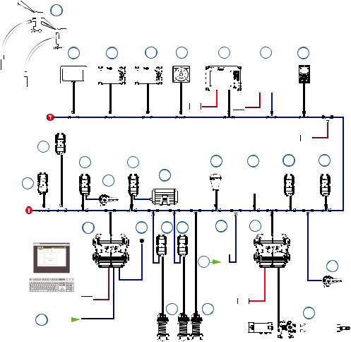
Hydra |
|
||
An example |
of a typical H5000 system. At the centre of the system is the H5000 Central |
||
Processor Unit (CPU). All sensor information is fed back to the CPU and can be easily controlled and configured via the Graphic display.
1
2 |
|
|
3 |
|
|
4 |
|
|
|
5 |
6 |
|
|
|
|
|
|
7 |
|
||||||||||||||||||||||
|
|
|
|
|
|
|
|
|
|
|
|
|
|
|
|
|
|
|
|
|
|
|
|
|
|
|
|
|
|
|
|
|
|
|
|
|
|
|
|
|
|
 12V
12V 
T
8 |
|
9 |
|
10 |
|
|
|
|
|
|
|
|
|
|
|
|
|
|
|
|
|
|
|
|
|
|
12V |
|
|
|
|
|
|
|
12 |
|
|
|||||||||||||||||||||||||||||||||
|
|
|
|
|
|
|
|
|
|
|
|
|
|
|
|
|
|
|
|
|
|
|
|
|
|
|
||||||||||||||||||||||||||||||||||||||||||||
|
|
11 |
|
|
|
|
||||||||||||||||||||||||||||||||||||||||||||||||||||||||||||||||
T |
|
|
|
|
|
|
|
|
|
|
|
|
|
|
|
|
|
|
|
|
|
|
|
|
|
|
|
|
|
|
|
|
|
|
|
|
|
|
|
|
|
|
|
|
|
|
|
|
|
|
|
|
|
|
|
|
|
|
|
|
|
|
|
|
||||||
|
|
|
|
|
|
|
|
|
|
|
|
|
|
|
|
|
|
|
|
|
|
|
|
|
|
|
|
|
|
|
|
|
|
|
|
|
|
|
|
|
|
|
|
|
|
|
|
|
|
|
|
|
|
|
|
|
|
|
|
|
|
|
|
|||||||
|
|
|
|
|
|
|
|
|
|
|
|
|
|
|
|
|
|
|
|
|
|
|
|
|
|
|
|
|
|
|
|
|
|
|
|
|
|
|
|
|
|
|
|
|
|
|
|
|
|
|
|
|
|
|
|
|
|
|
|
|
|
|
|
|||||||
|
|
|
|
|
|
|
|
|
|
|
|
|
|
|
|
|
|
|
|
|
|
|
|
|
|
|
|
|
|
|
|
|
|
|
|
|
|
|
|
|
|
|
|
|
|
|
|
|
|
|
|
|
|
|
|
|
|
|
|
|
|
|
|
|||||||
|
|
|
|
|
|
|
|
|
|
|
|
|
|
|
|
|
|
|
|
|
|
|
|
|
|
|
|
|
|
|
|
|
|
|
|
|
|
|
|
|
|
|
|
|
|
|
|
|
|
|
|
|
|
|
|
|
|
|
|
|
|
|
|
|||||||
|
|
|
|
|
|
|
|
|
|
|
|
|
|
|
|
|
|
|
|
|
|
|
|
|
|
|
|
|
|
|
|
|
|
|
|
|
|
|
|
|
|
|
|
|
|
|
|
|
|
|
|
|
|
|
|
|
|
|
|
|
|
|
|
|||||||
|
|
|
|
|
|
|
|
|
|
|
|
|
|
|
|
|
|
|
|
|
|
|
|
|
|
|
|
|
|
|
|
|
|
|
|
|
|
|
|
|
|
|
|
|
|
|
|
|
|
|
|
|
|
|
|
|
|
|
|
|
|
|
|
|||||||
|
|
|
|
|
|
|
|
|
|
|
|
|
|
|
|
|
|
|
|
|
|
|
|
|
|
|
|
|
|
|
|
|
|
|
|
|
|
|
|
|
|
|
|
|
|
|
|
|
|
|
|
|
|
|
|
|
|
|
|
|
|
|
|
|||||||
|
|
|
|
|
|
|
|
|
|
|
|
|
|
|
|
|
|
|
|
|
|
|
|
|
|
|
|
|
|
|
|
|
|
|
|
|
|
|
|
|
|
|
|
|
|
|
|
|
|
|
|
|
|
|
|
|
|
|
|
|
|
|
|
|||||||
14 |
|
|
|
|
|
|
|
|
|
|
15 |
|
|
|
|
|
|
|
16 |
|
|
|
|
|
|
|
|
|
|
|
|
|
|
|
|
|
|
|
|
|
|
|
|
|
|
|
|
|
|
|
|
|
|
|
|
|
|
|
||||||||||||
|
|
|
|
|
|
|
|
|
|
|
|
|
|
|
|
|
|
|
|
|
|
|
|
|
|
|
|
|
|
|
|
|
|
|
|
|
|
|
|
|
|
|
|
|
|
|
||||||||||||||||||||||||
|
|
|
|
|
|
|
|
|
|
|
|
|
|
|
|
|
|
|
|
|
|
|
|
|
|
|
|
|
|
|
|
|
|
|
|
|
|
|
|
|
|
|
|
|
|
|
|
|
|
|
|
|
|
|
|
|
|
|
|
|
||||||||||
|
|
12V |
|
|
|
|
|
|
|
|
|
|
|
|
|
|
|
|
|
|
|
|
|
|
|
|
|
|
|
|
|
|
|
|
|
|
|
|
|
|
|
|
|
|
|
|
|
|
|
|
|
|
|
|
|
|
|
|
|
|
|
|
|
|
|
|
|
|
|
|
|
|
|
|
|
|
|
|
|
|
|
|
|
|
|
|
|
|
|
|
|
|
|
|
|
|
|
|
|
|
|
|
|
|
|
|
|
|
|
|
|
|
|
|
|
|
|
|
|
|
|
|
|
|
|
|
|
|
|
|
|
|
|
|
|
|
|
|
|
|
|
13 |
|
|
|
|
|
|
|
|
|
|
|
|
|
|
|
|
|
|
|
|
|
|
|
|
|
12V |
|
|
|
|
|
|
|
|
|
|
|
|
|
17 |
|
|
|
|
|
|
|
|
||||||||||||||||||||||
|
|
|
|
|
|
|
|
|
|
|
|
|
|
|
|
|
|
|
|
|
|
|
|
|
|
|
|
|
|
|
|
|
|
|
|
|
|
|
|
|
|
|
|
|
|
|||||||||||||||||||||||||
|
|
|
|
|
|
|
|
|
|
|
|
|
|
|
|
|
|
|
|
|
|
|
|
|
|
|
|
|
|
|
|
|
|
|
|
|
|
|
|
|
|
|
|
|
|
|
|
|
|
|
|
|
|
|
|
|
|
|
|
|
|
|
|
|||||||
|
|
|
|
|
|
|
|
|
|
|
|
|
|
|
|
|
|
|
|
|
|
|
|
|
|
|
|
|
|
|
|
|
|
|
|
|
|
|
|
|
|
|
|
|
|
|
|
|
|
|
|
|
|
|
|
|
|
|
|
|
|
|
|
|||||||
|
|
|
|
|
|
|
|
|
|
|
|
|
|
|
|
|
|
|
|
|
|
|
|
|
|
|
|
|
|
|
|
|
|
|
|
|
|
|
|
|
|
|
|
|
|
|
|
|
|
|
|
|
|
|
|
|
|
|
|
|
|
|
|
|||||||
18
|
WIFI-1 |
|
12V |
19 |
20 |
|
No. |
Description |
|
No. |
Description |
|
|
|
|
|
|
|
1 |
Masthead unit |
11 |
|
Motion sensor (Heel / Trim only) |
|
|
|
|
|
|
|
2 |
HV Display |
12 |
|
Alarm module |
|
|
|
|
|
|
|
3 |
Graphic display |
13 |
|
Wireless access point WiFi-1 |
|
|
|
|
|
|
|
4 |
Race display |
14 |
|
Central processor unit |
|
|
|
|
|
|
|
5 |
Analogue display |
15 |
|
Man Overboard Button - MOB |
|
|
|
|
|
|
|
6 |
Zeus Touch |
16 |
|
H5000 Pilot Computer |
|
|
|
|
|
|
|
7 |
H5000 Pilot Controller |
17 |
|
Rudder reference unit |
|
|
|
|
|
|
|
8 |
RC42N compass |
18 |
|
Hydraulic ram |
|
|
|
|
|
|
|
9 |
GPS |
19 |
|
Speed sensor |
|
|
|
|
|
|
|
10 |
Baro / Air temp sensor |
20 |
|
Depth sensor |
|
|
|
|
|
|
|
|
Terminator |
|
|
|
12 Volt DC power supply |
T |
|
12V |
|
||
|
|
||||
|
|
|
|
||
|
|
|
|
|
|
System examples | H5000 Operation Manual |
| 13 |
Hercules
1
2 |
3 |
4 |
5 |
6 |
7 |
8 |
|
|
12V |
|
12V |
|
|
T |
|
|
|
|
|
|
|
|
|
|
|
12V |
|
9 |
|
11 |
13 |
14 |
15 |
16 |
|
10 |
12 |
|
|
|
|
|
|
|
|
|
|
|
T |
|
|
|
|
|
|
17 |
|
18 |
19 |
|
|
|
20 |
|
|
|
|
22 |
|
|
|
|
|
|
|
|
21 |
|
|
12V |
|
|
|
12V |
|
25 |
|
|
23 |
|
|
|
|
|
|
|
|
24 NMEA0183 Tx/Rx |
|
|
|
|
|
|
No. |
Description |
|
No. |
Description |
|
|
|
|
|
|
|
1 |
Vertical masthead unit |
14 |
|
Barometric / temperature sensor |
|
|
|
|
|
|
|
2 |
HV Display |
15 |
|
Motion sensor |
|
|
|
|
|
|
|
3 |
Graphic display |
16 |
|
Alarm module |
|
|
|
|
|
|
|
4 |
Race display |
17 |
|
Central processor unit |
|
|
|
|
|
|
|
5 |
Analogue display |
18 |
|
Man Overboard Button - MOB |
|
|
|
|
|
|
|
6 |
Zeus Touch |
19 |
|
H5000 Pilot Computer |
|
|
|
|
|
|
|
7 |
Zeus |
20 |
|
Webserver |
|
|
|
|
|
|
|
8 |
H5000 Pilot Controller |
21 |
|
Deckman |
|
|
|
|
|
|
|
9 |
Analog module |
22 |
|
Rudder reference unit |
|
|
|
|
|
|
|
10 |
Mast rotation sensor |
23 |
|
Hydraulic ram |
|
|
|
|
|
|
|
11 |
Serial module |
24 |
|
NMEA 0183 Tx / Rx |
|
|
|
|
|
|
|
12 |
Halcyon Gyro Stabilized Compass |
25 |
|
Speed sensor |
|
|
|
|
|
|
|
13 |
GPS |
26 |
|
Depth sensor |
|
|
|
|
|
|
|
|
Terminator |
|
|
|
12 Volt DC power supply |
T |
|
12V |
|
||
|
|
||||
|
|
|
|
||
|
|
|
|
|
|
14 | |
System examples | H5000 Operation Manual |
Performance
1
2 |
|
|
3 |
|
|
|
4 |
|
|
|
|
5 |
6 |
|
|
|
|
|
|
7 |
|
8 |
|
|
|
|||||||||||||||||
|
|
|
|
|
|
|
|
|
|
|
|
|
|
|
|
|
|
|
|
|
|
|
|
|
|
|
|
|
|
|
|
|
|
|
|
|
|
|
|
|
|
|
|
|
|
|
|
|
|
T |
|
|
|
|
|
|
|
|
|
|
|
|
|
|
|
|
|
|
|
|
|
|
|
|
|
|
|
|
|
|
|
|
|
|
|
|
|
|
|
|
|
|
|
|
|
|
|
12V |
|
|
|
|
|
|
|
12V |
|
|
|
|
|
|
|
|
|
|
|
|
|
|
|
|
|
|
|
|
|
|
|
|
|
|
|
|
|
|
|
|
|
||||||||||||||
|
|
|
|
|
|
|
|
|
|
|
|
|
|
|
|
|
|
|
|
|
|
|
|
|
|
|
|
|
|
|
|
|
|
|
|
|
|
|
|
|
|
|
|
|
|
|
|
|
|
|
|
|
|
|
|
|
|
|
|
|
|
|
|
|
|
|
|
|
|
|
|
|
|
|
|
|
|
|
|
|
|
|
|
|
|
|||||||||||||||||||||||||
|
|
|
|
|
|
|
|
|
|
|
|
|
|
|
|
|
|
|
|
|
|
|
|
|
|
|
|
|
|
|
|
|
|
|
|
|
|
|
|
|
|
|
|
|
|
|
|
|
|
|
|
|
|
|
|
|
|
|
|
|
|
|
|
|
|
|
|
|
|
|
|
|
|
|
|
|
|
|
|
|
|
|
|
|
|
|
|
|
|
|
|
|
|
|
|
|
|
|||||||||||||
|
|
|
|
|
|
|
|
|
|
|
|
|
|
|
|
|
|
|
|
|
|
|
|
|
|
|
|
|
|
|
|
|
|
|
|
|
|
|
|
|
|
|
|
|
|
|
|
|
|
|
|
|
|
|
|
|
|
|
|
|
|
|
|
|
|
|
|
|
|
|
|
|
|
|
|
|
|
|
|
|
|
|
|
|
|
|
|
|
|
|
||||||||||||||||||||
9 |
|
|
|
|
|
|
|
|
|
|
|
|
|
|
|
|
|
|
|
|
|
|
|
|
|
|
|
|
|
|
|
|
|
|
|
|
|
|
|
|
|
|
|
|
|
|
|
|
|
|
|
|
|
|
|
|
|
|
|
|
|
|
|
|
|
|
|
|
|
|
|
|
|
|
|
|
12V |
|
|
|
|
|
|
|
|
|
|
|||||||||||||||||||||||
|
|
|
|
|
|
|
|
|
|
|
|
|
|
|
|
|
|
|
|
|
|
|
|
|
|
|
|
|
|
|
|
|
|
|
|
|
|
|
|
|
|
|
|
|
|
|
|
|
|
|
|
|
|
|
|
|
|
|
|
|
|
|
|
|
|
|
|
|
|
|
|
|
|
|
|
|
|
|
|
|
|
|
|
|
|
|
|
|
|
|
|
|
|
|
|
|
|
|
|
|||||||||||
|
|
|
|
|
|
|
|
|
|
|
|
|
|
|
|
|
|
|
|
|
|
|
|
|
|
|
|
|
|
|
|
|
|
|
|
|
|
|
|
|
|
|
|
|
|
|
|
|
|
|
|
|
|
|
|
|
|
|
|
|
|
|
|
|
|
|
|
|
|
|
|
|
|
|
|
|
|
|
|
|
|
|
|
|
|
|
|
|
|
|
|
|
|
|
|
|
|
|
|
|||||||||||
|
|
|
|
|
|
|
|
|
|
|
|
|
|
|
|
|
|
|
|
|
|
|
|
|
|
|
|
|
|
|
|
|
|
|
|
|
|
|
|
|
|
|
|
|
|
|
|
|
|
|
|
|
|
|
|
|
|
|
|
|
|
|
|
|
|
|
|
|
|
|
|
|
|
|
|
|
|
|
|
|
|
|
|
|
|
|
|
|
|
|
|
|
|
|
|
|
|
|
|
|||||||||||
|
|
|
|
|
|
|
|
|
|
|
|
|
|
|
|
|
|
|
|
|
|
|
|
|
|
|
|
|
|
|
|
|
|
|
|
|
|
|
|
|
|
|
|
|
|
|
|
|
|
|
|
|
|
|
|
|
|
|
|
|
|
|
|
|
|
|
|
|
|
|
|
|
|
|
|
|
|
|
|
|
|
|
|
|
|
|
|
|
|
|
|
|
|
|
|
|
|
|
|
|||||||||||
|
|
|
|
|
|
|
|
|
|
|
|
|
|
|
|
|
|
|
|
|
|
|
|
|
|
|
|
|
|
|
|
|
|
|
|
|
|
|
|
|
|
|
|
|
|
|
|
|
|
|
|
|
|
|
|
|
|
|
|
|
|
|
|
|
|
|
|
|
|
|
|
|
|
|
|
|
|
|
|
|
|
|
|
|
|
|
|
|
|
|
|
|
|
|
||||||||||||||||
|
|
|
|
|
|
|
|
|
|
|
|
|
|
|
|
|
|
|
|
|
|
|
12 |
|
|
|
|
|
|
|
|
|
|
|
|
|
|
|
|
|
|
|
|
|
|
|
|
14 |
|
|
15 |
|
|
|
|
|
|
16 |
17 |
|
|
|
||||||||||||||||||||||||||||||||||||||||||||||||
|
|
|
|
|
|
|
|
|
|
|
|
|
|
|
|
|
|
|
|
|
|
|
|
|
|
|
|
|
|
|
|
|
|
|
|
|
|
|
|
|
|
|
|
|
|
|
|
|
|
|
|
|
|
|
||||||||||||||||||||||||||||||||||||||||||||||||||||||||
|
|
|
|
|
|
|
|
|
|
|
|
10 |
|
|
|
|
|
|
|
|
|
|
|
|
|
|
|
|
|
|
|
|
|
|
|
|
|
|
|
|
|
|
|
|
|
|
|
|
||||||||||||||||||||||||||||||||||||||||||||||||||||||||||||||
|
|
|
|
|
|
|
|
|
|
|
|
|
|
|
|
|
|
|
|
|
|
|
|
|
|
|
|
|
|
|
|
|
|
|
|
|
|
|
|
|
|
|
|
|
|
|
||||||||||||||||||||||||||||||||||||||||||||||||||||||||||||||||
9 |
|
|
|
|
|
|
|
|
|
|
|
|
|
|
|
|
|
|
|
|
|
|
|
|
|
|
|
11 |
|
|
|
|
|
|
|
|
|
|
|
|
|
|
|
|
|
|
13 |
|
|
|
|
|
|
|
|
|
|
|
|
|
|
|
|
|
|
|
|
|
|
|
|
|
|
|
|
|
|
|
|
|
|
|
|
|
|
|
|
|
|
|
|
|
|
|
|
|
|
|
|
|
|
|
|
|
||||||
T |
|
|
|
|
|
|
|
|
|
|
|
|
|
|
|
|
|
|
|
|
|
|
|
|
|
|
|
|
|
|
|
|
|
|
|
|
|
|
|
|
|
|
|
|
|
|
|
|
|
|
|
|
|
|
|
|
|
|
|
|
|
|
|
|
|
|
|
|
|
|
|
|
|
|
|
|
|
|
|
|
|
|
|
|
|
|
|
|
|
|
|
|
|
|
|
|
|
|
|
|
|
|
|
|
|
|
|
|
|
|
|
|
|
|
|
|
|
|
|
|
|
|
|
|
|
|
|
|
|
|
|
|
|
|
|
|
|
|
|
|
|
|
|
|
|
|
|
|
|
|
|
|
|
|
|
|
|
|
|
|
|
|
|
|
|
|
|
|
|
|
|
|
|
|
|
|
|
|
|
|
|
|
|
|
|
|
|
|
|
|
|
|
|
|
|
|
|
|
|
|
|
|
|
|
|
|
|
|
|
|
|
|
|
|
|
||||||
|
|
|
|
|
|
|
|
|
|
|
|
|
|
|
|
|
|
|
|
|
|
|
|
|
|
|
|
|
|
|
|
|
|
|
|
|
|
|
|
|
|
|
|
|
|
|
|
|
|
|
|
|
|
|
|
|
|
|
|
|
|
|
|
|
|
|
|
|
|
|
|
|
|
|
|
|
|
|
|
|
|
|
|
|
|
|
|
|
|
|
|
|
|
|
|
|
|
|
|
|
||||||||||
|
|
|
|
|
|
|
|
|
|
|
|
|
|
|
|
|
|
|
|
|
|
|
|
|
|
|
|
|
|
|
|
|
|
|
|
|
|
|
|
|
|
|
|
|
|
|
|
|
|
|
|
|
|
|
|
|
|
|
|
|
|
|
|
|
|
|
|
|
|
|
|
|
|
|
|
|
|
|
|
|
|
|
|
|
|
|
|
|
|
|
|
|
|
|
|
|
||||||||||||||
|
|
|
|
|
|
|
|
|
|
|
|
|
|
|
|
|
|
|
|
|
|
|
|
|
|
|
|
|
|
|
|
|
|
|
|
|
|
|
|
|
|
|
|
|
|
|
|
|
|
|
|
|
|
|
|
|
|
|
|
|
|
|
|
|
|
|
|
|
|
|
|
|
|
|
|
|
|
|
|
|
|
|
|
|
|
|
|
|
|
|
|
|
|
|
|
|
||||||||||||||
|
|
|
|
|
|
|
|
|
|
|
|
|
|
|
|
|
|
|
|
|
|
|
|
|
|
|
|
|
|
|
|
|
|
|
|
|
|
|
|
|
|
|
|
|
|
|
|
|
|
|
|
|
|
|
|
|
|
|
|
|
|
|
|
|
|
|
|
|
|
|
|
|
|
|
|
|
|
|
|
|
|
|
|
|
|
|
|
|
|
|
|
|
|
|
|
|
|
|
|
|||||||||||
18 |
|
|
|
19 |
|
|
|
|
|
|
20 |
|
20 |
|
|
|
21 |
23 |
|
|
|
|
|
|
|
|
|
|
|
|
|
|
|
|
|
|
|
|
|
|
|
|
|
|
|
|
|
|
||||||||||||||||||||||||||||||||||||||||||||||||||||||||||||||
|
|
|
|
|
|
|
|
|
|
|
|
|
|
|
|
|
|
|
|
|
|
|
|
|
|
|
|
|
|
|
|
|
|
|
|
|
|
|
|
|
|
|
|
|
|
|
|
|
|
|
|
|
|
|
|
|
|
|
|
|
|
|
|
|
|
|
|
|
|
|
|
|
|
|
|
|
|
|
|
|
|
|
|
|
|
|
|
|
|
|
|
|
|
|
|
|
|
|
|
|
|
|
|
|
|
|
|
|
|
|
|
|
|
|
|
|
|
|
|
|
|
|
|
|
|
|
|
|
|
|
|
|
|
|
|
|
|
|
|
|
|
|
|
|
|
|
|
|
|
|
|
|
|
|
|
|
|
|
|
|
|
|
|
|
|
|
|
|
|
|
|
|
|
|
|
|
|
|
|
|
|
|
|
|
|
|
|
|
|
|
|
|
|
|
|
|
|
|
|
|
|
|
|
|
|
|
|
|
|
|
|
|
|
|
|
|
|
|
|
|
|
|
|
|
|
|
|
|
|
|
|
|
|
|
|
|
|
|
|
|
|
|
|
|
|
|
|
|
|
|
|
|
|
|
|
|
|
|
|
|
|
|
|
|
|
|
|
|
|
|
|
|
|
|
|
|
|
|
|
|
|
|
|
|
|
|
|
|
|
|
|
|
|
|
|
|
|
|
|
|
|
|
|
|
|
|
|
|
|
|
|
|
|
|
|
|
|
|
|
|
|
|
|
|
|
|
|
|
|
|
|
|
|
|
|
|
|
|
|
|
|
|
|
|
|
|
|
|
|
|
|
|
|
|
|
|
|
|
|
|
|
|
|
|
|
|
|
|
|
|
|
|
|
|
|
|
|
|
|
|
|
|
|
|
|
|
|
|
|
|
|
|
|
|
|
|
|
|
|
|
|
|
|
|
|
|
|
|
|
|
|
|
|
|
|
|
|
|
|
|
|
|
|
|
|
|
|
|
|
|
|
|
|
|
|
|
|
|
|
|
|
|
|
26 |
22 |
24 |
|
||
|
|
|
|
|
12V |
|
|
|
|
|
|
29 |
|
12V |
|
|
|
|
|
|
|
|
|
|
|
|
|
|
|
|
|
|
|
|
|
|
||||||
28 |
|
25 |
|
|
|
|||||||||||||||||||||||||||||||||||
27 |
|
|
|
|
|
|
|
|
|
|
|
|
|
|
|
|
|
|
|
|||||||||||||||||||||
|
|
|
|
|
|
|
|
|
|
|
|
|
|
|
|
|
|
|
|
|
|
|
|
|
|
|
|
|
|
|
|
|
|
|
|
|
|
|
|
|
|
|
|
|
|
|
|
|
|
|
|
|
|
|
|
|
|
|
|
|
|
|
|
|
|
|
|
|
|
|
|
|
|
|
|
|
|
|
|
|
|
|
|
|
|
|
|
|
|
|
|
|
|
|
|
|
|
|
|
|
|
|
|
|
|
|
|
|
|
|
|
|
|
|
|
|
|
|
|
|
|
|
|
|
|
|
|
|
|
|
|
|
|
|
|
|
|
|
|
|
|
|
|
|
|
|
|
|
|
|
|
|
|
|
|
|
|
|
|
|
|
|
|
|
|
|
|
|
|
|
|
|
|
|
|
|
|
|
|
|
|
|
|
|
|
|
|
|
|
|
|
|
|
|
|
|
|
|
|
|
|
|
|
|
No. |
Description |
No. |
Description |
1 |
Fwd & Aft vertical masthead unit |
16 |
Motion sensor |
2 |
HV Display |
17 |
Alarm module |
3 |
Graphic display |
18 |
Central processor unit |
4 |
Race display |
19 |
Man Overboard Button - MOB |
5 |
Analogue display |
20 |
Analog module |
6 |
Zeus Touch |
21 |
Analog module |
7 |
Zeus |
22 |
Analog device * |
8 |
H5000 Pilot Controller |
23 |
H5000 Pilot Computer |
9 |
Analog module |
24 |
Rudder reference unit |
10 |
Analog module |
25 |
Hydraulic ram |
11 |
Mast rotation sensor |
26 |
Webserver |
12 |
Serial module |
27 |
Deckman |
13 |
Halcyon Gyro Stabilized Compass |
28 |
Port & Starboard speed sensor |
14 |
GPS |
29 |
NMEA 0183 Depth sensor |
15 |
Barometric / temperature sensor |
30 |
Depth sensor |
T |
Terminator |
12V |
12 Volt DC power supply |
¼ Note: * See analog expansion for more information on type and quantity of devices
System examples | H5000 Operation Manual |
| 15 |
Autopilot minimum system requirement
1 |
2 |
3 |
4 |
T
T
12V

5 |
7 |
|
|
8 |
10 |
12V |
12V |
9 |
|
|
|
|
6 |
|
No. |
Description |
|
No. |
Description |
|
|
|
|
|
|
|
1 |
Masthead unit |
6 |
|
Speed sensor |
|
|
|
|
|
|
|
2 |
Graphic display |
7 |
|
H5000 Pilot Computer |
|
|
|
|
|
|
|
3 |
H5000 Pilot Controller |
8 |
|
Rudder Reference Unit |
|
|
|
|
|
|
|
4 |
GPS antenna |
9 |
|
Hydraulic Ram |
|
|
|
|
|
|
|
5 |
H5000 Central Processor Unit |
10 |
|
Compass |
|
|
|
|
|
|
|
|
Terminator |
|
|
|
12 Volt DC power supply |
T |
|
12V |
|
||
|
|
||||
|
|
|
|
||
|
|
|
|
|
|
Basic System - No H5000 CPU
1 |
2 |
3 |
4 |
T
T
12V

5
No. |
Description |
No. |
Description |
1 |
Masthead unit |
4 |
ZG100 GPS |
|
|
|
|
2 |
HV Display |
5 |
DST800 Speed & Depth sensor |
3Graphic Display
T |
Terminator |
|
12V |
12 Volt DC power supply |
|
|
|||||
|
|
¼Note: A system without an H5000 CPU will only provide data from the available sensors on the network and limited functionality. Only those menu options visible on the Graphic Display will be available to the user.
16 | |
System examples | H5000 Operation Manual |

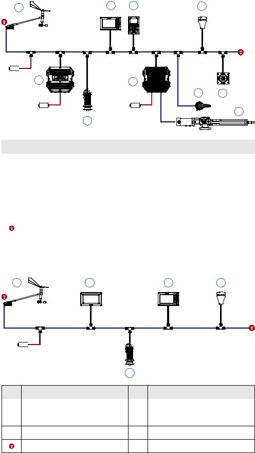
4Graphic displayOperation
MENU |
1
2
3
4
5
Basic operation
The first display added to the network will go into a startup wizard when it is first powered on. The startup wizard will need to be completed before the display can be used.
Using the wizard, set the desired language, time, units and network source selection.
1PAGE
Each short press of the PAGE key scrolls through the data pages. When viewing a data page a long
press of the PAGE key will bring up the pages menu, from here the required page can be selected directly from a list. From any dialog screen, pressing the PAGE key navigates back to the data pages. When using a menu the PAGE key navigates back a step.
2UP
Scrolls up through selected menus / set values
3ENTER
Used to enter the selected sub menus and confirm selection
4DOWN
Scrolls down through selected menus / set values
5 MENU / LIGHTS
MENU |
Single press of the MENU key – displays the Page menu |
|
Double press of the MENU key – displays the Settings menu |
||
|
||
|
Long press of the MENU key - Enters the display setup dialog and light settings menu. |
Display group
Light settings are replicated on all displays set to the same group.
Backlight level
Min to Max in 10% increments
Night mode
Alternative display palette for low light conditions.
Night mode color
Red, green, blue, white text color
¼Note: Adjusting the backlight settings will e ect all other displays in the same display group. See Network groups for more information.
Operation | H5000 Operation Manual |
| 17 |
Standby
MENU |
All of the displays can be placed in Standby mode via any display Setup dialog. |
¼ Note: Once in Standby mode a single press of the MENU key will turn the displays back on.
3sec
Default graphic display pages
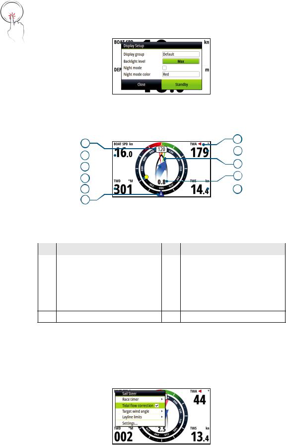
Sail Steer
|
1 |
|
|
|
|
7 |
|||
|
|
|
|
|
|
|
|
8 |
|
|
2 |
|
|
|
|
|
|
||
|
|
|
|
|
|
||||
|
|
|
|
|
9 |
||||
|
3 |
|
|
|
|
||||
|
|
|
|
|
10 |
||||
|
4 |
|
|
|
|
||||
|
|
|
|
|
|
|
|
|
|
|
5 |
|
|
|
|
|
|
11 |
|
|
|
|
|
|
|
||||
|
6 |
|
|
|
|
|
|
|
|
Displayed data |
|
|
|
|
|
|
|
||
|
|
|
|
|
|
||||
No. |
Description |
|
|
No. |
Description |
||||
|
|
|
|
||||||
1 |
Course / Heading |
7 |
Port / Starboard indicator |
||||||
|
|
|
|
||||||
2 |
Boat speed |
8 |
True Wind Angle |
||||||
|
|
|
|
||||||
3 |
Tide set |
9 |
Laylines |
||||||
|
|
|
|
||||||
4 |
Waypoint |
10 |
Tide rate |
||||||
|
|
|
|
||||||
5 |
True wind direction |
11 |
True Wind Speed |
||||||
6True wind indicator
¼Note: See configuring the Sail Steer page for more information on using this page
Configuring the Sail Steer page
When navigating to a waypoint you can configure the Sail Steer page to show laylines to aid navigation.
Tidal flow correction
Tidal flow correction will calculate the tidal flow and o set the laylines accordingly.
18 | |
Operation | H5000 Operation Manual |

Target wind angle
There are 3 sources available for target wind angle.
Polar
Takes the target wind angle from your polar table
Actual
Takes the current value of target wind angle
Manual
Manually input the upwind and downwind numbers into the dialog boxes.
Layline limits
When selected will show a dotted line indicating the minimum and maximum tack/gybe time period either side of the layline. This can be set from 5 to 30 minutes in 5 minute increments.
Speed / Depth
1
2 
3
Displayed data
No. |
Description |
No. |
Description |
1 |
Speed |
3 |
Depth |
2Acceleration bargraph
Operation | H5000 Operation Manual |
| 19 |
Wind plot
1 
 3
3
4
2 |
|
|
|
|
|
5 |
|
|
|
|
|
||
|
|
|
|
|
||
|
|
|
6 |
|||
|
|
|||||
Displayed data
No. |
Description |
No. |
Description |
|
|
|
|
1 |
True wind direction |
4 |
Mean value |
|
|
|
|
2 |
True wind direction histogram |
5 |
True Wind Speed histogram |
|
|
|
|
3 |
True Wind Speed |
6 |
Time period (5 to 60 minutes) |
|
|
|
|
¼Note: Wind histogram time periods can be set to show 1, 5, 10, 30 or a 60 minute history. Toggle between the time periods using the UP/DOWN keys.
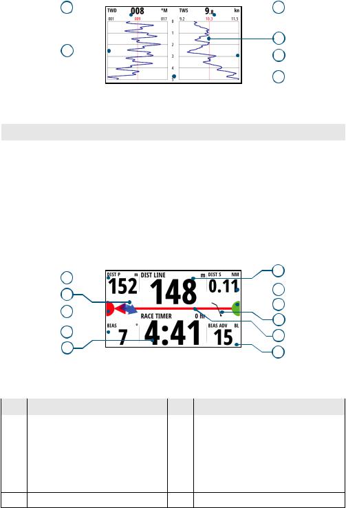
Start line
|
1 |
|
|
|
6 |
||
|
|
|
|
|
|
7 |
|
|
2 |
|
|
|
|
|
|
|
|
|
|
|
|||
|
|
|
|
|
|
8 |
|
|
3 |
|
|
|
|
|
|
|
|
|
|
|
|||
|
|
|
|
9 |
|||
|
|
|
|
|
|||
|
4 |
|
|
|
10 |
||
|
|
|
|
||||
|
|
|
|
|
|||
|
5 |
|
|
|
11 |
||
|
|
|
|
|
|||
Displayed data |
|
|
|
|
|||
|
|
|
|
||||
No. |
Description |
No. |
Description |
||||
|
|
|
|
||||
1 |
Distance to port end of start line |
7 |
Distance to starboard end of start line |
||||
|
|
|
|
||||
2 |
Tide direction indicator |
8 |
Starboard end start line indicator |
||||
|
|
|
|
||||
3 |
Port end start line indicator |
9 |
Wind indicator (wind barb) |
||||
|
|
|
|||||
4 |
Start line bias angle |
10 Start line - Arrow points to favored end |
|||||
|
|
|
|||||
5 |
Race timer |
11 Bias advantage (boat lengths) |
|||||
6Distance to start line (perpendicular)
20 | |
Operation | H5000 Operation Manual |
Setting up a Start line page
The Start Line page is used as a visual aid to boat distance from the start line, tide direction, recommended start end bias and what advantage in degrees and boat lengths the biased end will give.
¼Note: Before setting the start line position It is important that the Bow o set is updated to negate the di erence between the GPS postion and the bow of the vessel.
1 Approach the port end of the start line
2 Select ping from the start Line menu
3 Highlight Port end...
MENU
4 When the bow touches the start line, press the ENTER key.
5 The port end mark on the start line screen will go to solid red indicating it has been pinged
6 Repeat steps 1 to 4 at the starboard end selecting ping starboard end as the bow touches the line
7 The starboard end mark on the start line screen will go to solid green indicating it has been pinged
Operation | H5000 Operation Manual |
| 21 |

Start line screen explained
4
1
2 |
|
|
5 |
|
|
||||
|
|
|
|
|
|
|
|
|
|
3 |
6 |
|||
|
||||
Start line end not pinged (position not recorded)
Start line end pinged (position recorded)
Start line end stale (historic start line position)
Start line end becomes stale at 23:59 hrs on the day it was recorded but remains valid.
Invalid start line - One or more ends invalid (position not recorded)
Start line - Blue - Square line - No bias advantage
Start line - Red & Arrow left - Port end bias
Start line - Green & Arrow right - Starboard end bias
Tide direction indicator
Wind speed and direction indicator (wind barb)
1DIST P: Distance to port end of start line
2BIAS: Start line bias angle
3Race timer
4DIST LINE: Distance to start line (perpendicular)
5DIST S: Distance to starboard end of start line
6BIAS ADV: Bias advantage (boat lengths)
22 | |
Operation | H5000 Operation Manual |

Depth history
1 |
|
2 |
4 |
|
|
3 |
5 |
Displayed data
No. |
Description |
No. |
Description |
1 |
Current depth |
4 |
Water line |
|
|
|
|
2 |
Shallow water limit |
5 |
Depth histogram |
3Depth scale
¼Note: Depth histogram time periods can be set to show 5, 10, 30 or a 60 minute history. Toggle between the time periods using the UP/DOWN keys.
Highway
|
6 |
1 |
7 |
2 |
8 |
3 |
9 |
|
|
4 |
10 |
|
|
5 |
11 |
|
Displayed data
No. |
Description |
No. |
Description |
1 |
Waypoint bearing |
7 |
Estimated waypoint arrival time |
|
|
|
|
2 |
Course over ground |
8 |
Waypoint |
|
|
|
|
3 |
O course limit (user setting) |
9 |
Course line |
|
|
|
|
4 |
Distance to waypoint |
10 |
Vessel indicator |
|
|
|
|
5 |
Cross track error |
11 |
XTE correction direction Left or Right |
6Waypoint name
Operation | H5000 Operation Manual |
| 23 |
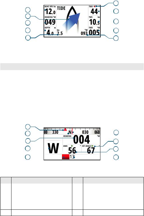
Tide
|
|
|
|
|
6 |
||
|
1 |
|
|
|
|
|
7 |
|
|
|
|
|
|
||
|
2 |
|
|
|
|
|
|
|
|
|
|
|
|
|
|
|
3 |
|
|
|
|
|
8 |
|
|
|
|
|
|||
|
|
|
|
|
|
|
|
|
4 |
|
|
|
|
|
9 |
|
|
|
|
|
|||
|
5 |
|
|
|
10 |
||
Displayed data |
|
|
|
|
|||
|
|
|
|
||||
No. |
Description |
No. |
Description |
||||
|
|
|
|
||||
1 |
Boat speed |
6 |
TWA Port / Starboard indicator |
||||
|
|
|
|
||||
2 |
Tide angle relative to vessel |
7 |
True Wind Angle |
||||
|
|
|
|
||||
3 |
Heading |
8 |
True Wind Speed |
||||
|
|
|
|
||||
4 |
Depth |
9 |
True wind direction |
||||
|
|
|
|
||||
5 |
Tide rate |
10 |
Tide direction |
||||
|
|
|
|
|
|
|
|
Autopilot
1 |
|
|
|
|
|
|
|
|
2 |
|
|
|
6 |
||||
|
|
|
|
|||||
|
||||||||
3 |
7 |
|||||||
4 |
|
8 |
||||||
|
||||||||
5 |
|
|
|
|
|
|
|
9 |
|
|
|
|
|||||
Displayed data
No. |
Description |
No. |
Description |
1 |
Set heading / Wind angle |
6 |
Heading indicator |
|
|
|
|
2 |
Compass scale |
7 |
Set heading / Wind / Rudder angle |
|
|
|
|
3 |
Heading |
8 |
Wind angle |
|
|
|
|
4 |
Autopilot mode indicator |
9 |
Rudder angle |
5Rudder angle indicator
24 | |
Operation | H5000 Operation Manual |

Data page transition
1
2
8
3
7
4
6
5
Available data pages
1 |
Sail steer (default) |
Full screen* |
2 |
Speed / Depth 2x1 grid (default) |
2x1 grid* |
3 |
Wind plot (default) |
2x2 grid* |
4 |
Start line (default) |
2x2 grid o set* |
5 |
Depth history (default) |
3x3 grid* |
6 |
Highway (default) |
1+3 digital* |
7 |
Tide (default) |
1+6 digital* |
8 |
Autopilot (default) |
Centre analog* |
|
Satellites |
Analog +2* |
|
Weather |
Analog +3* |
|
Single time plot* |
Dual analog* |
|
Dual time plot* |
|
¼ Note: * indicates, User configurable page
Operation | H5000 Operation Manual |
| 25 |

Replacing a data page
1 Go to the pages menu.
2 Highlight the page you wish to replace
MENU
x2
3 Press MENU
4 Highlight Replace and press the ENTER key
5 Highlight the desired page and press the ENTER key
The new chosen page will be shown in the pages list.
Enabling / Disabling a data page
To make a data page available via the PAGE key you will need to first ensure it has been selected as one of the eight available pages.
Once the page has been selected as one of the eight data pages you can enable / disable it
1 Highlight the required page via the pages menu
2 Press MENU
3 Highlight Enabled
4 Press the ENTER key to switch the page on or o .
¼ Note: A tick symbol next to the page denotes that the page is active.
26 | |
Operation | H5000 Operation Manual |
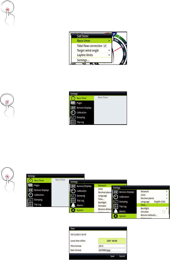
MENU
MENU
x2
MENU
x2
Menus
From a data page a single press of the MENU key will open the Page menu for that specific page. A double press of the MENU key will open up the Settings menu.
Page menu
The Page menu options vary from page to page. All Page menus have a race timer and settings option to access the Settings menu. All other options listed will relate directly to the current data page.
Settings menu
The Settings menu is where display options, display and system settings and calibration can be accessed.
Example menu structure
1 Select a menu as above.
2 Use the UP/DOWN and ENTER keys to navigate through the menu options.
¼ Note: Whilst navigating a menu a single press of the PAGE key will return to the previous menu option.
Example below: How to access the Time dialog via the Settings menu.
Operation | H5000 Operation Manual |
| 27 |
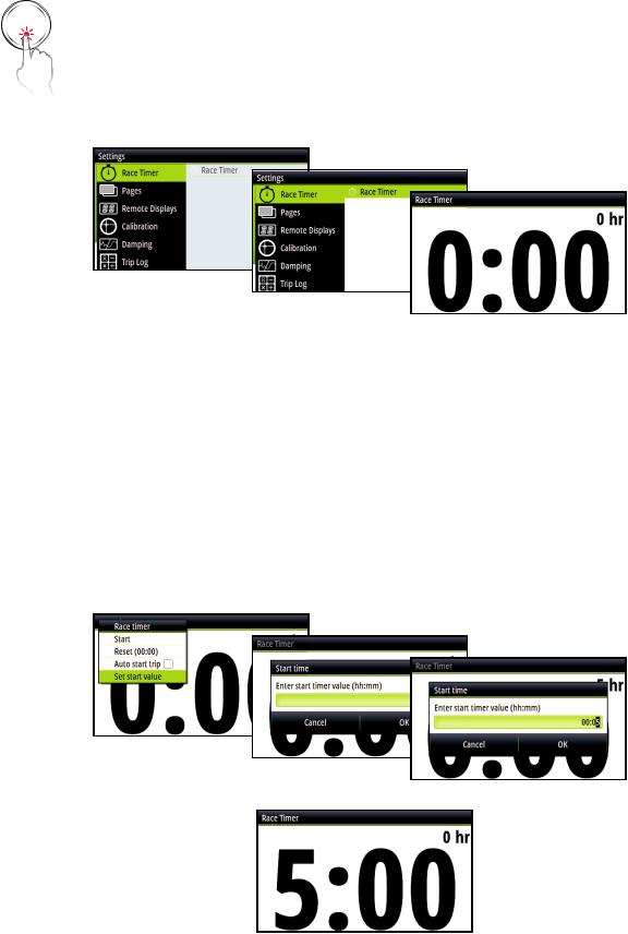
|
Race timer |
|
The race timer can be used to countdown to zero from a specified time, ideal for counting |
MENU |
down to a race start. It can also be used to count up from zero to record the elapsed time. |
|
The timer can be started at any time by selecting Start Timer from the timer setup menu. If |
x2 |
the start value is set to zero (00:00) when the timer is started the timer will begin counting up, |
recording the elapsed time. |
¼Note: The timer is shared between all displays on the network. All timer values are synchronized.
¼Note: The timer set value is in Hours : Minutes (hh:mm), the timer counter will show Minutes : Seconds (mm:ss) with the hours shown in the top right hand corner of the display.
Countdown timer
To count down to a race start, a time value can be set in the Set start value field in the Race Timer setup menu.
Set start value
1 Select the Start Time field.
2 Use the UP & DOWN keys to set the desired number
3 Press the the ENTER key to move to each consecutive number.
4 Press the PAGE key to exit the number edit field.
5 Once complete select OK to confirm.
¼ Note: Selecting Cancel or navigating away using the PAGE key will lose any changed settings.
When a time is present in the start value field the timer will begin to count down from that number when the timer is started. Once the time reaches zero it will begin counting up recording the elapsed time.
28 | |
Operation | H5000 Operation Manual |

Start/Stop timer
To start the timer, select Start in the Race Timer menu. When the timer is started it will return to the previous data page. To stop the timer from counting select Stop in the Race Timer menu.
Sync
When the timer is counting down selecting Sync will synchronize the time up or down to the nearest full minute.
Reset
Selecting Reset will reset the timer to the start value. If the timer was running, it will continue to run from the start value.
Auto start trip
Selecting Auto trip start will enable the Trip Log to record your time and mileage from the moment the countdown timer begins counting up from zero.
Operation | H5000 Operation Manual |
| 29 |
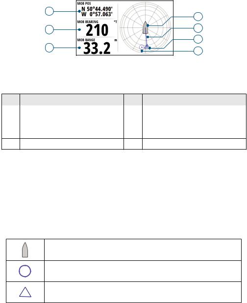
Man Over Board
If an emergency situation should occur and a man over board event is triggered, the display automatically switches to the MOB screen.
1 |
4 |
|
|
2 |
5 |
|
6 |
3 |
7 |
|
Displayed data
No. |
Description |
No. |
Description |
1 |
Last known MOB position |
5 |
Direction to MOB from vessel |
|
|
|
|
2 |
Bearing to MOB |
6 |
Dead reckoned MOB position |
|
|
|
|
3 |
Range to MOB |
7 |
Last known MOB position |
4Vessel (Always points up)
•A waypoint becomes active at the position the man over board is activated. This is indicated with a circular symbol. If the man over board event is activated via an AIS-SART then this position will update via the AIS-SART signal.
•The GPS longitude and latitude co-ordinates of the last known position are shown in the top left of the screen with the bearing and range MOB waypoint data listed below.
•If you have an H5000 CPU on the network the CPU will perform dead reckoning calculations to provide the estimated position of the man over board. This position will be displayed as a triangle symbol.
Vessel
Last known MOB position (H5000 CPU or MFD required)
Dead reckoned MOB position (H5000 CPU required)
¼ Note: To cancel the man over board event press MENU and select cancel.
30 | |
Operation | H5000 Operation Manual |
 Loading...