


CONTENTS |
|
GENERAL INTRODUCTION TO B&G NETWORK......... |
2 |
INTRODUCTION TO NETWORK QUAD......................... |
3 |
EXAMPLE SYSTEMS USING NETWORK QUAD........... |
4 |
SELECTING THE DISPLAY MODE ................................ |
5 |
USING THE SPEED KEY ................................................ |
6 |
CALIBRATION AND OPERATING PARAMETERS........ |
7 |
SETTING THE DISPLAY DAMPING ............................... |
8 |
SETTING THE SPEED AND LOG UNITS ....................... |
9 |
SPEED AND LOG CALIBRATION................................ |
10 |
1 - MANUAL CALIBRATION - CAL ................................ |
11 |
2 - MANUAL CALIBRATION - LOG CAL........................ |
12 |
3 - AUTOMATIC CALIBRATION - AUTO CAL ............... |
13 |
RESETTING THE DEAD RECKONED DISTANCE ....... |
15 |
USING THE DEPTH KEY .............................................. |
16 |
THE DEPTH DATUM - CAL ........................................... |
17 |
SETTING THE DEPTH DATUM..................................... |
18 |
SETTING THE DEPTH UNITS....................................... |
19 |
DEPTH ALARMS........................................................... |
20 |
SHALLOW ALARM |
|
ENABLING/DISABLING THE SHALLOW ALARM ......... |
21 |
ADJUSTING THE SHALLOW ALARM VALUE .............. |
21 |
DEEP ALARM |
|
ENABLING/DISABLING THE DEEP ALARM.................. |
22 |
ADJUSTING THE DEEP ALARM VALUE....................... |
22 |
ANCHOR ALARM |
|
USING THE ANCHOR ALARM....................................... |
23 |
ENABLING/DISABLING THE ANCHOR ALARM............ |
24 |
ADJUSTING THE ANCHOR ALARM SHALLOW LIMIT .25 |
|
ADJUSTING THE ANCHOR ALARM DEEP LIMIT......... |
25 |
USING THE TIMER/TEMP KEY ..................................... |
26 |
RESETTING THE TRIP LOG.......................................... |
27 |
SETTING THE TIMERS AND LAP TIMER ..................... |
28 |
SETTING THE TEMPERATURE UNITS......................... |
29 |
CALIBRATING THE TEMPERATURE SENSOR ............ |
30 |
USING THE LIGHTS KEY .............................................. |
31 |
NETWORK ALARMS ..................................................... |
32 |
FAULT AND ERROR MESSAGES ................................. |
33 |
INSTALLATION.............................................................. |
34 |
SITING THE UNIT........................................................... |
34 |
MOUNTING THE UNIT ................................................... |
34 |
SPECIFICATION ............................................................ |
36 |
610-HB-0503-05 |
1 |

GENERAL INTRODUCTION TO B&G NETWORK
The B&G Network range of instruments is designed to be used as individual units or connected together to form an integrated navigational system. A single network cable is used to carry data and power between units. The latest technology and screened cables throughout the Network System ensure the ultimate protection from interference between units and other systems. All Network instruments can be linked to Network PILOT, Network CHART, Network GPS or Network LORAN receivers or via NMEA 0183 (v1.5) to other navigational equipment.
INSTRUMENTS
Network SPEED
Network DEPTH
Network QUAD
Network WIND
Network TACK
Network DATA
NAVIGATIONAL AIDS
Network NAV
Network GPS
Network LORAN
LCD CHART
AUTOPILOTS
Network PILOT
610-HB-0503-05
INTRODUCTION TO NETWORK QUAD
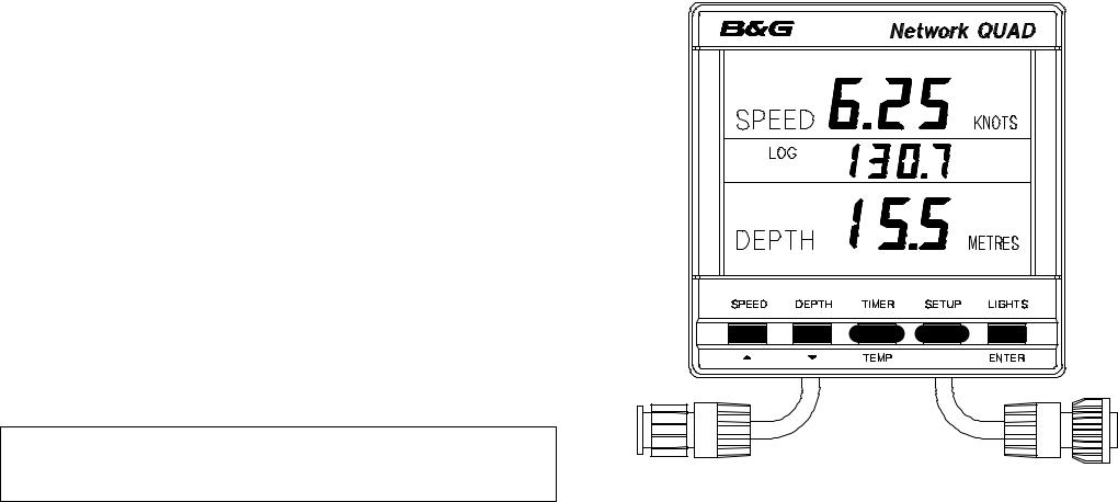
The Network QUAD unit measures and displays Speed, Depth, Log, Timer and Sea Temperature information on a large back-lit Liquid Crystal Display (LCD). The LCD is divided into three display areas. The top area permanently shows speed information, the centre area is selectable and shows Log, timer, sea temperature and depth alarm information, and the bottom area permanently shows depth information.
The five keys allow selection of the displayed information and setting of the units mode, calibration factors and operating parameters.
It can operate as the main Network QUAD unit either alone or as part of an Integrated Network Instrument System taking inputs directly from Speed and Depth Sensors which plug into the sockets at the rear of the display, or as a repeater (by selecting repeater mode) of information received via the two Network cable tails.
The Network QUAD REPEATER (not a Network QUAD in repeater mode) does not have Speed and Depth Sensor sockets, so it only receives data via the system network. It offers identical facilities to a Network QUAD main unit but can only ever be used as a repeater.
2
INTRODUCTION TO NETWORK QUAD CONT'D |
|
NETWORK QUAD DISPLAY UNIT |
The Network QUAD unit has three adjustable alarms:
1. Shallow water alarm
2. Deep water alarm
3. Anchor alarm
An internal alarm buzzer will sound when an alarm condition is met and the display will flash. The alarm is broadcast to all other Network Instruments in an integrated system, they will also sound their alarms and flash their displays (except Network WIND and Network TACK).
The Network QUAD unit is NOT able to transmit NMEA 0183 (v1.5), however, the Network QUAD REPEATER unit is able to transmit NMEA data via the system network cables to other Network units and connect to an NMEA device e.g. a position fixer, with a special NMEA output cable.
IMPORTANT NOTE
Your Network QUAD unit must be set-up and calibrated correctly before it is used as part of a navigational system.
610-HB-0503-05 |
3 |

EXAMPLES SYSTEMS USING NETWORK QUAD
Only one Network QUAD unit should have speed and depth sensors connected to it and set to transducer mode. Up to three more Network QUAD (set to repeater mode) or QUAD REPEATER units can be connected on to the system network.
QUAD |
|
|
QUAD |
|
|
|
QUAD |
|
QUAD |
||||||
Main unit |
Repeater Mode |
Repeater Mode |
Repeater unit |
||||||||||||
|
|
|
|
|
|
|
|
|
|
|
|
|
|
|
|
|
|
|
|
|
|
|
|
|
|
|
|
|
|
|
|
|
|
|
|
|
|
|
|
|
|
|
|
|
|
|
|
Depth |
Speed |
Sensor |
Sensor |
When in repeater mode, if the data is not |
SPEED |
|
being received from the system network, the  display will show OFF when a key is DEPTH

 pressed.
QUAD |
|
WIND |
QUAD |
PILOT |
|
|
|
|
|
|
|
|
|
|
|
|
|
Depth |
Speed |
Sensor |
Sensor |
If the Network QUAD unit losses valid depth data, due either the actual depth being outside the working range, or to extreme turbulence in the water the LCD will show 3 "floating" bars. This shows that the unit is attempting to calculate the depth and is still functioning.
610-HB-0503-05 |
4 |

SELECTING THE DISPLAY MODE
The Network QUAD unit has two operating modes. The correct mode must be selected for your Network system to operate properly.
tYPEt Transducer mode, the unit uses and displays speed and depth data from sensors connected directly into the display unit.
tYPEr Repeater mode, the unit operates as a repeater using data from the system network.
Press TIMER key |
Press SETUP key |
Press ENTER key |
Use S or T to |
Press ENTER to |
Press TIMER to |
to display stored |
to display the |
if the mode needs |
change mode. |
store the new |
complete the |
log. |
current mode. |
to be changed. |
|
mode in memory. |
change. |
610-HB-0503-05 |
5 |
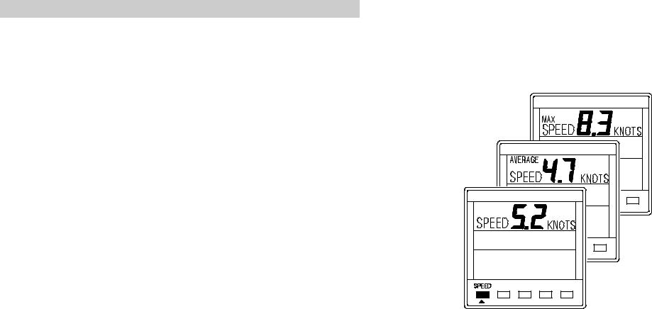
USING THE SPEED KEY
Boat speed information is permanently displayed in the top area of the LCD.
Press the SPEED key to cycle through the following options:
SPEED |
Current boat speed in Knots, can also be |
|
displayed in MPH. |
AVERAGE |
Average boat speed since the last reset of |
SPEED |
the trip log. |
MAX |
Maximum boat speed since the last reset |
SPEED |
of the trip log. |
610-HB-0503-05 |
6 |

CALIBRATION AND OPERATING PARAMETERS
When current boat speed is displayed, press the SETUP key to cycle through the following options:
DAMPING |
The response time of the display to |
|
changes in boat speed. |
SPEED |
The boat speed can be displayed in Knots |
KNOT |
or MPH. This setting also changes the log |
|
units to Nautical or Statute Miles. |
CAL |
Manual boat speed and log calibration. |
LOG |
Manual boat speed and log calibration. |
CAL |
|
AUTO CAL |
Automatic boat speed and log |
|
calibration. |
dr |
Reset Dead Reckoned Distance. |
When in SETUP mode:
•The SPEED key becomes the UP key S
•The LOG key becomes the DOWN key T
•The LIGHTS key becomes the ENTER key
The procedures for using the SETUP options are on the following pages.
610-HB-0503-05 |
7 |

SETTING THE DISPLAY DAMPING
Damping allows the response time of the displayed speed value to be slowed down if it is to jumpy in rough weather, or to sped it up when the conditions are calm. The damping works by averaging the values over a set time period; the longer the time period the smoother the readings, however the longer it takes to see a change. Similarly the shorter it is the jumpier the readings, but the faster the response.
The Network QUAD unit has a factory set value of 5, this can be adjusted in the range 1 to 64, each step is approximately one second.
Press SPEED key |
Press SETUP key |
Press ENTER key |
Use S or T to |
Press ENTER key |
Press SPEED key |
to display current |
once to display |
if the value is to |
change the value. |
to memorise the |
to display current |
boat speed. |
the damping |
be changed. |
|
change. |
boat speed. |
|
value. |
|
|
|
|
610-HB-0503-05 |
8 |

SETTING THE SPEED AND LOG UNITS
The Network QUAD can be set to display boat speed in Knots or MPH.
If boat speed is in Knots then log is in Nautical Miles. If boat speed is in MPH then log is in Statute Miles.
Press SPEED key |
Press SETUP key |
to display current |
twice. The speed |
boat speed. |
digits will blank. |
Press ENTER key |
Use S or T to |
Press ENTER key |
Press SPEED key |
if the units are to |
change the units. |
to memorise the |
to display current |
be changed. |
|
change. |
boat speed. |
610-HB-0503-05 |
9 |

SPEED AND LOG CALIBRATION
Before Network QUAD is used for navigation the boat speed and log have to be calibrated to ensure accuracy for your installation and the boats hull characteristics.
Three methods are available with the Network QUAD unit, two manual adjustments and one automatic:
MANUAL CALIBRATION
1.CAL The displayed boat speed value is corrected manually to read a known measured speed.
2.LOG The units calibration figure (Hz/Knot) is CAL manually adjusted to correct log and speed
inaccuracy.
AUTOMATIC CALIBRATION
3. AUTO CAL The unit automatically calibrates and corrects the boat speed and log.
Use the one of the methods overleaf to calibrate your instrument. It is recommended that AUTO CAL is used as this method will ensure the most accurate calibration of your Network QUAD unit.
610-HB-0503-05 |
10 |
METHOD 1. - MANUAL CALIBRATION - CAL
This procedure requires a reference boat speed with which to compare the Network QUAD units displayed boat speed. For example, another boat with an accurate calibrated log, or if the top speed of the boat is known this value can be entered during a sea trial to correct the
displayed value.
NOTE: The accuracy of this method is dependent upon the accuracy of the reference boat speed.
The example below shows a displayed boat speed of 5.2 knots, the boat speed is known to be 6.0 knots. The displayed value is adjusted to read 6.0 knots.
IMPORTANT NOTE: This method of calibration must not be carried out at boat speeds of LESS THAN 3 KNOTS as inaccurate values can be entered into the units memory. If the speed and log are not functioning correctly then enter a calibration value of 5.3 to 6.2 and then re-enter the correct calibration value as described below.
Press SPEED key |
Press SETUP key |
Press ENTER key |
Use S or T to |
Press ENTER to |
Press SPEED key |
to display current |
three times to |
to adjust the |
change the value. |
store the new |
to complete the |
boat speed. |
display CAL. |
displayed value. |
|
value in memory. |
change. |
610-HB-0503-05 |
11 |
 Loading...