


V60-B
Table of contents
 Loading...
V60/V60-B & H60
Fixed Mount VHF &
Wireless Handset
User Guide
ENGLISH
bandg.com

Preface
Disclaimer
As Navico is continuously improving this product, we retain the
right to make changes to the product at any time which may not be
reflected in this version of the manual. Please contact your nearest
distributor if you require any further assistance.
It is the owner’s sole responsibility to install and use the equipment
in a manner that is legal and will not cause accidents, personal
injury or property damage. The user of this product is solely
responsible for observing safe boating practices.
NAVICO HOLDING AS AND ITS SUBSIDIARIES, BRANCHES AND
AFFILIATES DISCLAIM ALL LIABILITY FOR ANY USE OF THIS PRODUCT
IN A WAY THAT MAY CAUSE ACCIDENTS, DAMAGE OR THAT MAY
VIOLATE THE LAW.
Governing Language: This statement, any instruction manuals,
user guides and other information relating to the product
(Documentation) may be translated to, or has been translated from,
another language (Translation). In the event of any conflict between
any Translation of the Documentation, the English language
version of the Documentation will be the official version of the
Documentation.
This manual represents the product as at the time of printing.
Navico Holding AS and its subsidiaries, branches and affiliates
reserve the right to make changes to specifications without notice.
2 |
Copyright
Copyright © 2019 Navico Holding AS.
Warranty
The warranty card is supplied as a separate document.
In case of any queries, refer to the brand website of your unit or
system: www.bandg.com
Licensing Information
• The user is advised to check the radio operating licensing
requirements of your country before using this VHF radio. The
operator is solely responsible for observing proper radio installation
and usage practices.
• In some regions/countries, a Radio Operator’s license is required
| V60/V60-B User Guide

and it is your responsibility to determine whether such a license is
required before operating the radio.
• The frequencies used by this radio are reserved for Maritime use
only and those frequencies must be included on your Radio
Operator’s license.
• A valid USER MMSI number must be entered into this radio before
DSC functions can be used. You must apply for an MMSI number
which is usually obtained from the same authority that issues the
radio operator’s license. Contact the appropriate licensing authority
in your country. If you’re unsure who to contact, consult your B&G
dealer.
• A valid ATIS ID number must be entered into this radio before ATIS
functions can be used. An ATIS ID number is issued by Ofcom when
you add one or more pieces of ATIS equipment to your Ship Radio
Licence.
Important information
• This B&G DSC VHF radio is designed to generate a digital maritime
distress call to facilitate search and rescue. To be effective as a
safety device, this radio must be used only within the geographic
range of a shore-based VHF marine Channel 70 distress and safety
watch system. The geographic range may vary but under normal
conditions is approximately 20 nautical miles.
•
This radio can be configured to operate in your region/country of
operation. The user can select the region/country of operation during
the initial setup of the radio. This is a once-only operation. Should you
require to change the region/country, consult your B&G dealer.
Regulatory Compliance Statements
European Union
Navico declare under our sole responsibility that the V60/V60-B and
H60 conforms with the requirements of Directive 2014/53/EU (RED).
All compliance documents are available from the product’s section
in the following website: www.navico-commercial.com
EU RF exposure compliance notice for Fixed Mount VHF
To be protected against all verified adverse effects, the separation
distance of at least 2.1 m must be maintained between the antenna
of the radio having max. 6 dBi antenna and all persons.
| V60/V60-B User Guide
| 3

Countries of intended use in the EU
AT - Austria HU - Hungary PL - Poland
BE - Belgium IS - Iceland PT - Portugal
BG - Bulgaria IE - Ireland RO - Romania
CY - Cyprus IT - Italy SK - Slovak Republic
CZ - Czech Republic LV - Latvia SI - Slovenia
DK - Denmark LI - Liechtenstein ES - Spain
EE - Estonia LT - Lithuania SE - Sweden
FI - Finland LU - Luxembourg CH - Switzerland
FR - France MT - Malta TR - Turkey
DE - Germany NL - Netherlands UK - United Kingdom
GR - Greece NO - Norway
United States
Part 15 of the FCC Rules. Operation is subject to the following two
conditions: (1) this device may not cause harmful interference, and
(2) this device must accept any interference received, including
interference that may cause undesired operation.
Warning
The user is cautioned that any changes or modifications not
expressly approved by the party responsible for compliance could
void the user’s authority to operate the equipment.
4 |
RF Emissions notice
This equipment complies with FCC radiation exposure limits set
forth for an uncontrolled environment. This device’s antenna must
be installed in accordance with provided instructions; and it must
be operated with minimum 2.1 m spacing between the antennas
and all person’s body (excluding extremities of hands, wrist and feet)
during operation. Further, this transmitter must not be co-located or
operated in conjunction with any other antenna or transmitter.
¼ Note: This equipment has been tested and found to comply with
the limits for a Class B digital device, pursuant to Part 15 of the FCC
Rules. This equipment generates, uses and can radiate radio frequency energy and, if not installed and used in accordance with
the instructions, may cause harmful interference to radio communications. However, there is no guarantee that the interference will
not occur in a particular installation. If this equipment does cause
harmful interference to radio or television reception, which can
| V60/V60-B User Guide

be determined by turning the equipment off and on, the user is
encouraged to try to correct the interference by one or more of the
following measures:
• Reorient or relocate the receiving antenna.
• Increase the separation between the equipment and receiver.
• Connect the equipment into an outlet on a circuit different from
that of the receiver is connected.
• Consult the dealer or an experienced technician for help.
RF Exposure Compliance Statement for Handset
This device was tested for typical body-worn operations. To comply
with RF exposure requirements, a minimum separation distance of
0 mm must be maintained between the user’s body and the
handset, including the antenna.
FCC Part 18 Compliance Statement for Cradle Charger (BC-12)
This device complies with Part 18 of the FCC Rules.
CAUTION: Changes or modifications not expressly approved by the
party responsible for compliance could void the user’s authority to
operate the product.
¼ Note: This equipment has been tested and found to comply with
the limits for a wireless power transfer, pursuant to Part 18 of the FCC
Rules. These limits are designed to provide reasonable protection
against harmful interference in a residential installation. This equipment generates, uses and can radiate radio frequency energy and,
if not installed and used in accordance with the instructions, may
cause harmful interference to radio communications. However, there
is no guarantee that interference will not occur in a particular installation. If this equipment does cause harmful interference to radio
or television reception, which can be determined by turning the
equipment off and on, the user is encouraged to try to correct the
interference by one or more of the following measures:
• Reorient or relocate the receiving antenna.
• Increase the separation between the equipment and receiver.
• Connect the equipment into an outlet on a circuit different from
that of the receiver is connected.
• Consult the dealer or an experienced technician for help.
| V60/V60-B User Guide
| 5

FCC RF exposure compliance for Cradle Charger (BC-12)
This device complies with FCC radiation exposure limits set forth
for an uncontrolled environment. This transmitter must not be
co-located or operating in conjunction with any other antenna or
transmitter.
Canada
This device complies with CAN ICES-3(B)/NMB-3(B) and contains
license-exempt transmitter(s)/receiver(s) that comply with
Innovation, Science and Economic Development Canada’s licenseexempt RSS(s). Operation is subject to the following two conditions:
1. This device may not cause interference.
2. This device must accept any interference, including interference that
may cause undesired operation of the device.
L’émetteur/récepteur exempt de licence contenu dans le
présent appareil est conforme aux CNR d’Innovation, Sciences et
Développement économique Canada applicables aux appareils
radio exempts de licence. L’exploitation est autorisée aux deux
conditions suivantes:
1. L’appareil ne doit pas produire de brouillage.
2. L’appareil doit accepter tout brouillage radioélectrique subi, même si
le brouillage est susceptible d’en compromettre le fonctionnement.
Industry Canada Statement
This equipment complies with IC RSS-102 radiation exposure limits
set forth for an uncontrolled environment. This transmitter must not
be co-located or operating in conjunction with any other antenna
or transmitter. This equipment should be installed and operated
with minimum distance 2.1 m between the radiator and your body.
Cet équipement est conforme aux limites d’exposition aux
radiations IC CNR-102 établies pour un environnement non
contrôlé. Cet émetteur ne doit pas être situé ou fonctionner
conjointement avec une autre antenne ou un autre émetteur. Cet
équipement doit être installé et utilisé avec une distance minimale
de 2.1 m entre le radiateur et votre corps.
6 |
Under Industry Canada regulations, this radio transmitter may
only operate using an antenna of a type and maximum (or lesser)
gain approved for the transmitter by Industry Canada. To reduce
potential radio interference to other users, the antenna type and its
gain should be so chosen that the equivalent isotropically radiated
| V60/V60-B User Guide

power (e.i.r.p.) is not more than that necessary for successful
communication.
Conformément à la réglementation d’Industrie Canada, le présent
émetteur radio peut fonctionner avec une antenne d’un type et
d’un gain maximal (ou inférieur) approuvé pour l’émetteur par
Industrie Canada. Dans le but de réduire les risques de brouillage
radioélectrique à l’intention des autres utilisateurs, il faut choisir
le type d’antenne et son gain de sorte que la puissance isotrope
rayonnée quivalente (p.i.r.e.) ne dépassepas l’intensité nécessaire à
l’établissement d’une communication satisfaisante.
This radio transmitter has been approved by Industry Canada to
operate with the antenna types listed below with the maximum
permissible gain and required antenna impedance for each antenna
type indicated. Antenna types not included in this list, having a gain
greater than the maximum gain indicated for that type, are strictly
prohibited for use with this device.
Le présent émetteur radio a été approuvé par Industrie Canada pour
fonctionner avec les types d’antenne énumérés ci-dessous et ayant
un gain admissible maximal et l’impédance requise pour chaque
type d’antenne. Les types d’antenne non inclus dans cette liste, ou
dont le gain est supérieur au gain maximal indiqué, sont strictement
interdits pour l’exploitation de l’émetteur.
IC RF exposure compliance for H60 Wireless Handset and Cradle Charger (BC-12)
This equipment complies with IC RSS-102 radiation exposure limits
set forth for an uncontrolled environment. This transmitter must not
be co-located or operating in conjunction with any other antenna
or transmitter.
Cet équipement est conforme aux limites d’exposition aux
radiations IC CNR-102 établies pour un environnement non
contrôlé. Cet émetteur ne doitpas être situé ou fonctionner
conjointement avec une autre antenne ou un autre émetteur.
Australia & New Zealand
Complies with the requirements of level 2 devices of the Radio
communications (Electromagnetic Compatibility) standard 2017
and Radiocommunications (VHF Radiotelephone Equipment –
Maritime Mobile Service) Standard 2014.
| V60/V60-B User Guide
| 7

Trademarks
B&G® and Navico® are registered trademarks of Navico.
NMEA® and NMEA 2000® are registered trademarks of the National
Marine Electronics Association.
DSC (Digital Selective Calling)
Digital Selective Calling offers significant safety and convenience
advantages over older VHF radios without this functionality.
• A valid USER MMSI must be entered into this radio before DSC
functions can be used.
• Many countries do not have radio repeaters that support DSC
message relaying. However DSC can still be useful for direct ship-toship communication, where the other vessel is also equipped with a
DSC capable radio.
• DSC distress calls generated by this radio are limited to the same
range restrictions that apply to regular VHF transmissions. The
vessel sending a distress can only rely upon DSC if within range of a
GMDSS Coast Radio Station. Typical VHF range may be about 20NM,
though this varies greatly depending upon installation, antenna
type, meteorological conditions, etc.
ATIS (Automatic Transmitter Identication
System)
• ATIS is required for vessels making VHF transmissions whilst on the
inland waterways of the Regional Arrangement Concerning the
Radiotelephone Service on Inland Waterways (RAINWAT) signatory
countries.
• RAINWAT is an agreement to implement common principles and
rules for the safe carriage of people and goods on Inland Waterways.
• The signatory countries are: Austria, Belgium, Bulgaria, Croatia, the
Czech Republic, France, Germany, Hungary, Luxembourg, Moldova,
Montenegro, the Netherlands, Poland, Romania, Serbia, the Slovak
Republic and Switzerland.
• Where a VHF is required on the inland waterways of the signatory
countries, this must be capable of ATIS transmissions, and have the
feature activated.
• The use of ATIS is prohibited outside the European inland waterways
covered by the Basel Agreement.
8 |
| V60/V60-B User Guide

MMSI and ATIS ID
The user MMSI (Marine Mobile Service Identity) is a unique nine
digit number. It is used on marine transceivers that are capable of
using DSC (Digital Selective Calling).
• An MMSI remains with a vessel, even if the vessel is sold on.
• An MMSI has 9 numeric digits (xxxxxxxxx). Your MMSI must not
commence with a ‘0’.
• A Group Call ID begins with ‘0’ followed by 8 numeric digits
(0xxxxxxxx).
• A Coast Station MMSI begins with 00 followed by 7 numeric digits
(00xxxxxxx).
• By law, you are not able to change your MMSI once it is entered into
the radio. This is why there is the confirmation screen when entering
the MMSI. If you need to have the MMSI in the radio changed, the
radio must be taken back to your B&G dealer.
• An ATIS ID is only required in certain EU countries when navigating
some inland waterways. It is usually a different number to your
MMSI.
AIS CLASS-B Safety Warning (V60-B only)
Warning: The AIS transceiver in this V60-B radio is an aid to
navigation and must not be relied upon to provide accurate
navigation information. AIS is not a replacement for vigilant human
lookouts and other navigation aids such as RADAR. Also, take
note that not all vessels will have an AIS transceiver turned on,
or installed. The performance of the transceiver may be seriously
impaired if not installed as instructed in the user manual, or due to
other factors such as weather and or nearby transmitting devices.
Important information for US customers
There are specific laws in the USA regarding the configuration of AIS
class B transceivers. If you are a US resident and intend to use your
AIS class B transceiver in US waters, you should make sure that your
retailer has configured your product prior to supplying it to you. If
your AIS transceiver has not been pre-configured, please contact
your dealer for details of how to have it configured.
| V60/V60-B User Guide
| 9

About this manual
!
This manual is a reference guide for installing and operating a V60/
V60-B VHF radio. Important text that requires special attention from
the reader is emphasized as follows:
¼ Note: Used to draw the reader’s attention to a comment or some
important information.
Warning: Used when it is necessary to warn personnel that
they should proceed carefully to prevent risk of injury and/or
damage to equipment/personnel.
10 |
| V60/V60-B User Guide

Contents
13 General Information
14 How to display and navigate menus
17 Key functions
23 Radio menus
23 Scan
24 Watch
25 Display
26 Radio setup
30 DSC/ATIS setup
32 AIS setup
35 Alarms
36 Wireless handset
37 Reset
38 DSC call menu
38 DSC calls
41 Track buddy
42 Contacts
43 AIS menu
43 About AIS
44 AIS receiver function (V60 and V60-B)
44 AIS transmitter function (V60-B)
45 AIS information and display
48 Hailer / Fog Horn / Intercom
48 Using the Hailer (PA) function
49 Using the Fog Horn
49 Using the Intercom facility
50 Wireless handset
50 Using the wireless handset
50 Using the Intercom facility
Contents | V60/V60-B User Guide
| 11

51 My channels
52 Shortcuts
53 Installation
53 What’s in the box
54 Installation options
54 Selecting a suitable mounting location
60 Cradle charger (BC-12)
61 First startup configuration
63 Specications
69 Channel charts
69 EU and INTERNATIONAL channel chart
77 USA channel chart
79 CANADA channel chart
82 Dimensional drawings
82 V60/V60-B fixed mount VHF
83 V60/V60-B hand mic
84 Handset Cradle Charger (BC-12)
85 H60 wireless handset
12 |
86 NMEA 2000 compliant PGN list
Contents | V60/V60-B User Guide

1
General Information
Your V60/V60-B provides the following useful features:
• AIS dual channel receiver to receive and display AIS targets
• AIS Class-B Transmitter to transmit your vessels position and details
(V60-B only) - requires additional VHF antenna to be installed
• Ability to communicate with up to 2 optional wireless handsets (H60)
• 6-key removable handset microphone with built-in speaker. Can be
front or rear connected to the radio with optional extension cable
• Built-in GPS receiver and antenna with connection for optional
external GPS antenna
• Intercom, Fog Horn and Hailer functions
• NAV/MOB key to display dedicated navigation or Man Over Board
screens
• TRI key to select DUAL/TRI scan
• Dedicated Wx (Weather) key
• Favourite channels list to build your list of commonly used channels
• Shortcuts list to build your list of commonly used radio features
• Access to all currently-available marine VHF channel banks (USA,
Canada, International) including weather channels where available
(country mode dependant)
• Dedicated CH16/9 key for quick access to the priority (international
distress) channel
• DSC (Digital Selective Calling) capability that meets Global DSC
Class D Standards
• DISTRESS call button to automatically transmit the MMSI and
position until an acknowledgement is received
• ATIS facility for inland waterways (EU country mode)
• With DSC Auto-Switch disable and DSC Test function
• Contacts list that stores up to 50 names with MMSI numbers
• MMSI storage for one favourite group
• Group Call and All Ships Call facility
• Weather alert facility where available (US country mode)
• Prominent channel display
• Adjustable contrast settings for the LCD
• Adjustable keypad backlighting for easy night-time use
• Waterproof and submersible to comply with IPx7
• Choice of High (25 W) or Low (1 W) transmission power
• Powerful 4 W external audio output
• GPS latitude and longitude (LL) and time display (with valid GPS
source)
• LL position polling information.
General Information | V60/V60-B User Guide
| 13
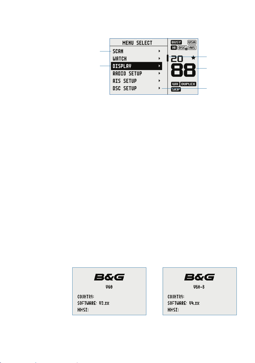
How to display and navigate menus
1
4
1. Split screen display – showing Main menu.
2. Split screen display – showing Channel screen.
3. Scroll bar indicates additional options above and below displayed
text.
4. Current menu item is selected using the channel knob.
5. Arrow indicates additional sub-menu items in this menu option.
¼ Note: Press the X button to step backwards to the previous menu
page, or exit the menus completely.
3
2
5
Entry of alphanumeric data
Rotate the channel knob to scroll through the alphanumeric
characters.
Press channel knob, to select and step to the next character.
To step backwards, press the MENU button. Press X to cancel entry
and return to previous menu.
14 |
LCD symbols and meanings
When the V60/V60-B starts up it momentarily displays the brand,
model, country mode, software version, and MMSI.
General Information | V60/V60-B User Guide
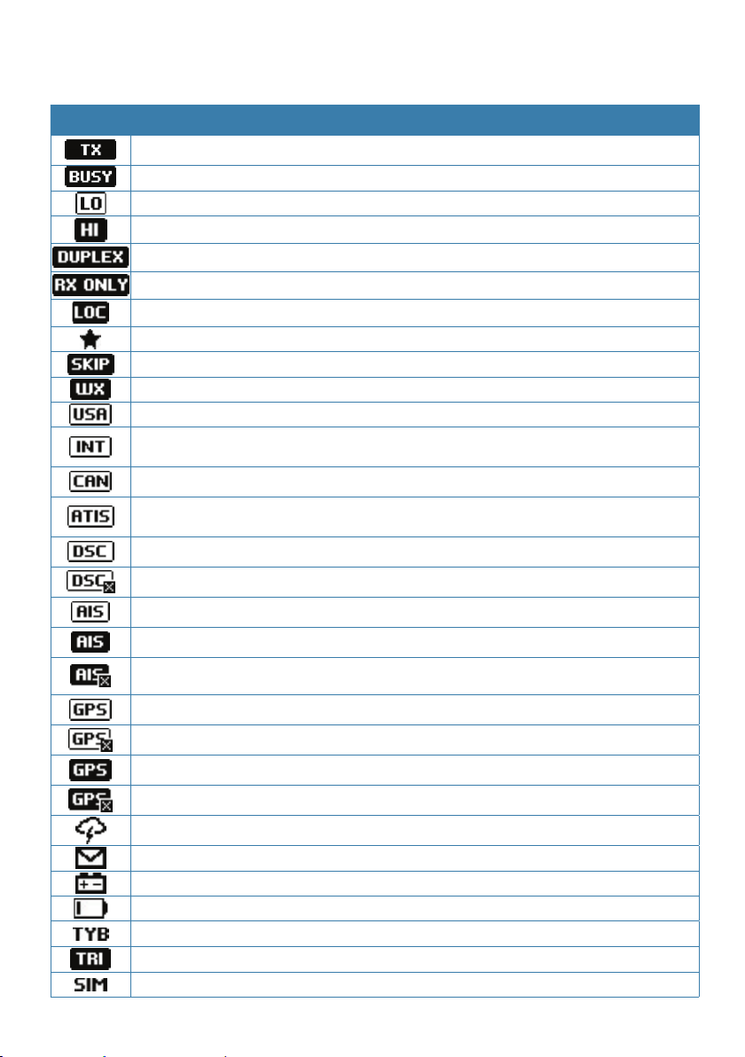
Symbol Meaning
Radio is transmitting
Receiver busy with incoming signal
Low Transmit power selected (1W)
High Transmit power selected (25W)
Current channel is Duplex (off when Simplex)
Current channel is receive only
Local mode enabled (used when in areas of high radio traffic, i.e. inner harbour)
Channel is saved as a favourite
Channel will be skipped during a scan
Weather channel stored by user (EU & INT country modes only)
Channel bank is set to USA
Channel bank is set to International. (Channels available depends on selected
country mode)
Channel bank is set to Canada
ATIS functionality is enabled (EU country mode only - must be enabled when in
European inland waterways)
DSC functionality is enabled
During normal operation, the following icons may be displayed on
the screen depending on setup:
DSC functionality is enabled, auto switch is turned off
AIS function is enabled - Receive only mode
AIS Class-B function is enabled – Transmit and Receive mode (V60-B only)
AIS Class-B Silent Switch mode is active – AIS transmissions are disabled (V60-B
only)
Internal GPS is enabled, with valid 3D fix
Internal GPS is enabled, no fix
External GPS is enabled, with valid 3D fix
External GPS is enabled, no fix
Weather alert enabled (USA/CAN only)
Missed DSC call
Low Battery (vessel) warning (activates at 10.5 V)
Battery level (wireless handset)
Track your Buddy feature is active
Current channel is selected as the Watch channel
GPS simulator is active
General Information | V60/V60-B User Guide
| 15
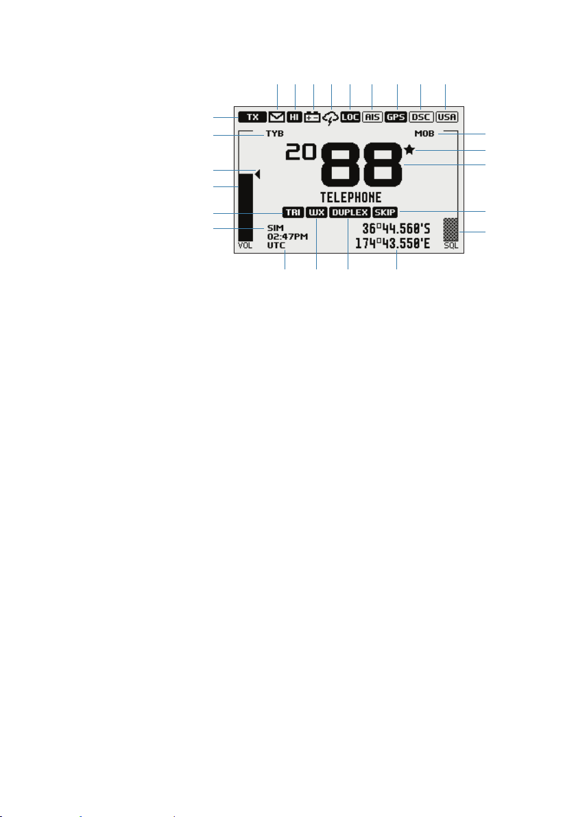
A typical display:
3
6
4
8
2 1 18 15 19 17 16 14 13
24
5
12
23
21
9 22 20 10
1. Channel is set to high power transmit
2. Missed call in the DSC call log
3. Channel is busy
4. Volume is under active control (solid black indicates control is active)
5. Current channel saved in ‘My Channels’
6. Track your buddy is enabled
7. Current channel will be skipped during a scan
8. Volume level indicator
9. Time (derived from GPS) - UTC offset is applied
10. Latitude/Longitude
11. Squelch level indicator (greyed out means control is not active)
12. Channel number (2 or 4 digits)
13. The USA channel bank is active
14. DSC functionality is enabled, but autoswitch is off
15. Weather alert function is enabled
16. Internal GPS is enabled, with 3D fix
17. AIS receiver is enabled
18. Low vessel voltage alert
19. Sensitivity mode is set to LOCAL
20. Current channel is Duplex
21. GPS Simulate mode is active
22. Current channel is set as the Weather channel (use Wx key to select)
23. Current channel is set as the Watch channel (use TRI key to select)
24. MOB waypoint is active.
7
11
16 |
General Information | V60/V60-B User Guide
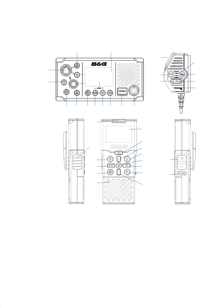
Key functions
The following describes the direct functions of the keys/knobs.
Where necessary, additional detail on any menus accessed by keys is
covered in following chapters.
4
1
5
7
3
2
8 9 10 11 12 13 18
13
17
5
10
4
19
24
17
24
12
15
20
21
11
15
9
12
23
22
6
15
14
1616
19
1. Channel knob / Press to Select
Tur n knob for channel selection, menu scrolling, alphanumeric
entry, and fine adjustment of backlight level (dependent on active
menu).
Short press to make selections in menus.
Long press to open MY CHANNELS.
2. VOL / SQL
Volume and Squelch level.
Short press knob to select which control to adjust. Which is
currently selected is indicated by a small triangular arrow above
the level bar for each option. Turning the knob clockwise increases
setting, anti-clockwise decreases it. Volume control is common to
General Information | V60/V60-B User Guide
| 17

internal and external speaker.
Long press to open SHORTCUTS.
3. X (EXIT)
Press X when navigating menus, to clear incorrect entries, to
exit from a menu without saving changes, and to back up to the
previous screen.
4. DSC CALL / MENU SELECT (Radio and wireless handset)
Short press to enter the DSC Call Menu and make DSC calls.
Long press to open the MENU SELECT page.
5. AIS / IC (Radio and wireless handset)
Short press to enter the AIS (Automatic Identification System) mode.
See page 32 for AIS setup and AIS functionality.
Long press to enter Intercom / Hailer / Fog Horn mode.
See page 50 for Intercom functionality and page 48 for Fog
Horn / Hailer functionality.
6. Zoom keys
Used in AIS mode.
Press TRI (zoom in) or SCAN (zoom out) to change the scale of the
AIS plotter. The scales available are: 1, 2, 4, 8, 16, 32 nm.
7. Power / Backlight
Short Press to adjust backlight level sequentially.
Repeated short press of the power button will step through large
backlight adjustments. The Channel knob can be used to make finer
adjustments.
Long press to turn radio on or off.
18 |
8. NAV / MOB
Short press to enter the NAV (Navigation) mode. The screen will
change to navigation mode displaying the vessel’s current SOG and
COG.
Press X to exit NAV mode and return to normal radio operation
mode.
Long press to mark the current location with a Man-Over-Board
(MOB) waypoint. The screen will change to MOB navigation mode to
General Information | V60/V60-B User Guide
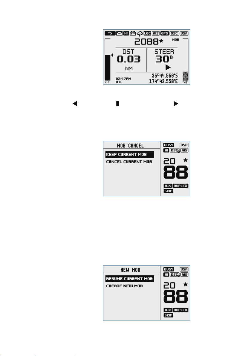
help navigate back to the MOB location:
DST (Distance to MOB waypoint).
STEER (Bearing to MOB waypoint) and direction indicators using
for turn to port, for straight ahead and for turn to stbd
(starboard).
Long press X to exit MOB navigation. A pop up screen will appear
with 2 choices:
1. KEEP CURRENT MOB: to return to normal operation mode without
cancelling MOB navigation.
2. CANCEL CURRENT MOB: to cancel current MOB navigation and
return to normal radio operation mode.
Or, short press X to close the pop up and resume current MOB
navigation.
Long press NAV/MOB to set a new MOB waypoint at the current
location. A pop up screen will appear with 2 choices:
1. RESUME CURRENT MOB: to close pop up and resume current
MOB navigation.
General Information | V60/V60-B User Guide
| 19

20 |
2. CREATE NEW MOB: to cancel current MOB navigation and create a
new Man-Over-Board (MOB) waypoint at the current location.
Or, short press X to close the pop up and resume current MOB
navigation.
¼ Note: Long press TRI and SCAN keys on the wireless handset to set a
MOB waypoint.
9. Weather key (Radio and wireless handset)
Short press (US/CAN country mode): press to hear the most recently
selected NOAA/Canadian weather station.
For non US/CAN country modes, changes channel to user
programmed choice. When in ATIS mode, will select CH10.
Long press (non US/CAN country mode): to store current channel as
the weather, local harbor or preferred channel.
10. SCAN / ZOOM- (Radio and wireless handset)
• Normal radio mode:
Short press to enter ALL SCAN mode.
ALL SCAN sequentially scans all channels for activity.
When a signal is received, scanning stops at that channel and the
BUSY icon appears on the screen. If the signal ceases for more than 5
seconds, the scan automatically resumes.
Turn the channel knob to temporarily skip over (lock out) a busy
channel and resume the scan. The direction turned determines if
the scan goes up or down the channel numbers (ie ‘forward’ or
‘reverse’). If it is still busy when the scan completes a full cycle, it will
stop again at this channel. Note that it is not possible to skip over the
priority channel.
Press ENT to permanently skip over the channel. The SKIP icon will
show on the LCD for this channel.
To cancel a skipped channel, select the channel while in normal
mode (non-scan mode) then press the ENT key - the SKIP icon will
disappear. Repowering the radio also restores all skipped channels.
Press SCAN or X while scanning is active to stop at the current
channel and return to normal operation.
Long press SCAN from normal operation to enter the SCAN menu.
• AIS mode:
Short press to increase (zoom out) the scale of the AIS plotter out
one range at a time. The scales available are: 1, 2, 4, 8, 16, 32 nm.
11. TRI / ZOOM+ (Radio and wireless handset)
• Normal radio mode:
Short press to start DUAL WATCH or TRI WATCH (if ‘watch’ channel
set).
Long press to set the current channel as the watch channel.
General Information | V60/V60-B User Guide

When a short press is made on the TRI key, the radio will either
switch to DUAL or TRI watch mode depending on whether a watch
channel has been setup.
Without a watch channel the radio will go to DUAL WATCH, where
the channels ‘watched’ are the current channel and the priority
channel (the distress channel, CH16 for most countries).
With a watch channel selected, TRI WATCH is enabled, where the
channels ‘watched’ are the current channel the ‘watch’ channel, and
the priority channel (the distress channel, CH16 for most countries).
If the radio is set to ‘Country: USA’, two priority channels are watched
- Channel 9 and Channel 16.
• AIS mode:
Short press to reduce (zoom in) the scale of the AIS plotter out one
range at a time. The scales available are: 1, 2, 4, 8, 16, 32 nm.
12. 16 / 9 (Radio, handset mic and wireless handset)
Short press to change to priority channel. Press again to return to
original channel. The default Priority Channel is CH16.
For US country mode: Long press to make Channel 09 the priority
channel.
13. DISTRESS (Radio and wireless handset)
Short press to start a distress call, where the nature of distress can
be selected from a list.
Long press the distress button to initiate an ‘undesignated’ distress
call.
The Distress call is broadcast to all DSC equipped radios, so will
create an alarm on every DSC radio within range.
If position information is available it will be included in the
transmition.
14. H/L (Transmission power) (Handset mic only)
Press to toggle between high (25 W) or low (1 W) transmission
power for the entire channel bank. The HI or LO selection is shown
on the LCD.
Some channels allow only low power transmissions. Error beeps will
sound if attempting to change the transmission power while on one
of these channels.
Some channels allow only low power transmissions initially, but can
be overridden to high power by pressing (and holding) H/L after
depressing PTT. Keep the H/L button pressed down after releasing
the PTT button, if wanting to transmit again on high power.
15. Channel change (Handset mic and wireless handset)
Short press () goes up one channel, or () goes down one
General Information | V60/V60-B User Guide
| 21

channel. Holding either key will, after a short delay, step rapidly
through the channels.
16. VOL +/- (Volume) (Handset mic only)
Change the volume on the handset microphone.
Short press (+) increases the volume, or (-) decreases the volume.
17. PTT (Push-to-talk) (Handset mic and wireless handset)
Press button to transmit. Only depress for duration of message to be
broadcast. Radio can’t receive while it is transmitting.
18. Handset microphone (front) connection. Plug in the removable
handset microphone. Alternatively, it can be connected to the rear
of the radio.
19. MIC (Microphone) (Handset mic and wireless handset)
The microphone can be connected to the front MIC connector or
rear MIC connector. An optional 5 m or 10 m extension cable is
available for mounting the microphone in a different location.
20. POWER / EXIT (Wireless handset)
Short press to EXIT when navigating menus, to clear incorrect
entries, to exit from a menu without saving changes, and to back up
to the previous screen.
Long press to turn radio on or off.
21. OK / H/L (Wireless handset)
Short press to make selections in menus.
Long press to change transmission power - see item 14.
22 |
22. VOL / SQL (Wireless handset)
Short press to select which control (Volume and Squelch) to adjust.
Use the + & - buttons to adjust.
23. +/- (Wireless handset)
Short press to adjust the selected control (Volume and Squelch).
24. LCD (Display) (Radio and wireless handset)
General Information | V60/V60-B User Guide
2
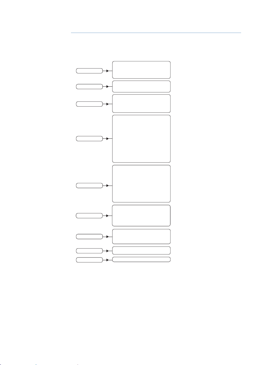
Radio menus
A long press of the MENU button opens MENU SELECT page. The
following shows the menu structure (top and 2nd level only):
ALL SCAN
ALL CHANNELS + 16
SCAN
WATC H
DISPLAY
RADIO SETUP
DSC SETUP
AIS SETUP
ALARMS
WIRELESS HANDSET
RESET
MY CHANNELS
MY CHANNELS + 16
EDIT MY CHANNELS (choose channels)
DUAL WATCH
TRI WATCH
SET WATCH CHANNEL (choose channel)
TIME DISPLAY (ON / OFF)
POS DISPLAY (ON / OFF)
COG/SOG (ON / OFF)
BACKLIGHT (>)
CONTRAST (0-10)
SENSITIVITY (DISTANT/LOCAL)
UIC (>)
POWER OUTPUT (HIGH/LOW)
CH NAME (>)
KEY BEEP (0-10)
UNITS (>)
INT SPEAKER (ON/OFF)
EXT SPEAKER (ON/OFF)
GPS (>)
COM PORT (>)
TIME (>)
VESSEL CALLSIGN (>)
AUTO POWER ON (AUTO/MANUAL)
MENU TIMEOUT (0-15 MINS)
DSC FUNCTION (X)
USER MMSI (>)
ATIS FUNCTION (ON/OFF)
SEA/INLAND MODE (SEA/INLAND)
ATIS ID (>)
INDIVIDUAL ACK (AUTO/MANUAL)
POS ACK (OFF/AUTO/MANUAL)
AUTO SWITCH (ON/OFF)
TEST ACK (AUTO/MANUAL)
RX DISTR WHILE OFF (X)
DSC TIMEOUT (>)
AIS FUNCTION ( X)
SILENT MODE (ON/OFF)
AIS DISPLAY (MMSI/NAME)
CPA (>)
TCPA (>)
CONFIG VESSEL (>)
GPS ALERT (>)
WX ALERT (>)
DSC ALARM (>)
CPA ALARM (>)
PAIR A HANDSET (>)
REMOVE A HANDSET (>)
(YES/CANCEL)
(US/CAN & INT country modes)
(EU country mode)
(EU country mode)
(EU country mode)
(V60-B only)
(V60-B only)
(US/CAN country mode)
Key:
(>) further menu options
(X) toggle selection. ‘X’ means option enabled.
Scan
This menu is for choosing a scan mode to enable, as well as
selection of the channels scanned per the MY CHANNELS list.
¼ Note: Scanning is not available if ATIS mode is turned on.
Radio menus | V60/V60-B User Guide
| 23

All scan
Scans all channels cyclically.
All channels + 16
Scans all channels cyclically, but checks the priority channel after
every channel step.
My channels
Scan all channels selected in EDIT MY CHANNELS.
My channels + 16
Scans all channels selected in EDIT MY CHANNELS, while also
checking the priority channel after every channel step.
Edit my channels
Allows creation of a custom list of channels - used in a MY
CHANNELS scan.
24 |
Watch
This menu is for choosing a watch mode to enable, as well as
selection of the watch channel. Watch modes can be thought of as
a channel scan on a subset of channels, where scanned channels
are ‘listened’ to briefly every 3 seconds, to determine if there is any
active radio communication.
¼ Note: Watch modes are not available if ATIS mode is turned on.
Dual watch
Select this to watch the current channel and the priority channel
(Channel 16).
Radio menus | V60/V60-B User Guide

TRI watch
Select this to watch the current channel, the user selected ‘watch’
channel, and the priority channel (Channel 16).
Set Watch Channel
Allows a watch channel to be selected from all available channels.
Selected channel is used by TRI WATCH mode.
¼ Note: If the radio is configured for USA market, two priority channels
are watched: Channel 9 and Channel 16.
Display
This menu allows the user to partially customize the screen
information displayed, and adjust the screen for best visibility to suit
the user and operating conditions.
Time display
Select to switch the display of Time to ON or OFF.
If turned ON, the display of COG/SOG is turned off, due to screen
space constraints.
LOC (Local Time) is displayed below the time if a UTC (Coordinated
Universal Time) offset has been entered; otherwise UTC is shown in
it’s place if no offset has been applied.
POS display
Select to switch ON or OFF the display of position provided from
connected GPS. If no GPS is connected and a manual entry has
been made, the position will be displayed prefixed with an ‘M‘.
COG/SOG
Select to switch ON or OFF the display of COG/SOG provided from
the selected GPS source.
If turned ON, Time display is turned OFF, due to screen space
constraints.
Backlight
Backlight level
Select to make adjustment to the backlight level using the Channel
knob. Range is 1 to 10.
Press MENU SELECT button to activate night mode (inverts display).
Radio menus | V60/V60-B User Guide
| 25

Network group
Set this value to the same as other B&G devices on NMEA 2000 in
order to control backlight levels simultaneously. To keep backlight
control inpedenent, set to a value not used elsewhere.
Contrast
Select to make adjustment of the screens contrast, using the
Channel knob. Range is 00 to 10.
Radio setup
The Radio setup menu covers settings that are typically configured
at installation, and seldom need changing.
Sensitivity
Use LOCAL/DISTANT to improve the sensitivity of the receiver either
locally (LOCAL) or over distances (DISTANT ).
LOCAL is not recommended for use in open sea conditions. It is
designed for use in areas of high radio noise; for example, close to a
busy port or city.
UIC
Select between USA, INT (International) or CAN (Canadian) channel
banks. The selected channel bank is displayed on the LCD along
with the last used channel. All the channel charts are shown in
chapter 11.
26 |
¼ Note: UIC is not available in EU country mode.
Power output
Select to toggle between HI (25 W) or LO (1 W) transmission
power for the entire channel bank. The or is shown on
the LCD, depending on your selection. Low power transmission
draws significantly less current (about 1/4) from the battery, so is
recommended for short range communication, and where battery
capacity is limited.
¼ Note: Some channels can’t be switched to high power, and will
show LO regardless of power output setting in menu.
CH name
CH NAME gives you the option to edit or delete the channel name
descriptions displayed on the screen. Select to edit the existing
Radio menus | V60/V60-B User Guide

description of the channel currently in use. It can be a maximum of
12 characters long.
Key beep
Select to allow adjustment of key beep volume.
Volume can be set from 00 - 10 (where 00 is off, and 10 is loudest).
Units
Select SPEED to choose whether displayed in KNOTS, MPH, or KPH.
Select COURSE to toggle between displaying in MAGNETIC or TRUE.
A true north heading is corrected for magnetic variation. A magnetic
north heading source must also output magnetic variation data if
the heading is to be displayed as a true north value.
Int speaker
Select to switch the radio’s internal speaker ON or OFF.
Ext speaker
Select to switch the radio’s external speaker port ON or OFF.
GPS
Manual
Select MANUAL to enter a GPS position (and time) from another
source when radio is not receiving position data from an internal or
networked source.
The manually entered GPS position can be used in DSC calls, but not
in AIS. AIS will be disabled.
If POS Display is turned ON, the latitude and longitude are shown on
the screen with a prefix ‘M’ indicating manual entry.
¼ Note: The manual entry is automatically replaced when a real GPS
position is received via the NMEA 0183, NMEA 2000 or Internal GPS,
depending on the GPS SOURCE setting.
Radio menus | V60/V60-B User Guide
| 27
Loading...