


ZEUSTouch
Operator Manual
ENGLISH
www.bandg.com

Preface
As Navico is continuously improving this product, we retain the right to make changes to the product at any time which may not be reflected in this version of the manual. Please contact your nearest distributor if you require any further assistance.
It is the owner’s sole responsibility to install and use the instrument and transducers in a manner that will not cause accidents, personal injury or property damage. The user of this product is solely responsible for observing safe boating practices.
NAVICO HOLDING AS AND ITS SUBSIDIARIES, BRANCHES AND AFFILIATES DISCLAIM ALL LIABILITY FOR ANY USE OF THIS PRODUCT IN A WAY THAT MAY CAUSE ACCIDENTS, DAMAGE OR THAT MAY VIOLATE THE LAW.
Governing Language: This statement, any instruction manuals, user guides and other information relating to the product (Documentation) may be translated to, or has been translated from, another language (Translation). In the event of any conflict between any Translation of the Documentation, the English language version of the Documentation will be the official version of the Documentation.
This manual represents the product as at the time of printing. Navico Holding AS and its subsidiaries, branches and affiliates reserve the right to make changes to specifications without notice.
Copyright
Copyright © 2013 Navico Holding AS.
Warranty
The warranty card is supplied as a separate document.
In case of any queries, refer to the brand web site of your display or system: www.bandg.com
Declarations and conformance
This equipment is intended for use in international waters as well as coastal sea areas administered by countries of the E.U. and E.E.A. For more information refer to the separate Zeus Touch Installation manual.
About this manual
This manual is a reference guide for operating the B&G Zeus Touch systems. It assumes that all equipment is installed and configured, and that the system is ready to use.
The manual assumes that the user has basic knowledge of navigation, nautical terminology and practices.
The manual does not cover basic background information about how equipment such as radars, echo sounders and AIS work. Such information is available from our web site: www.bandg.com
Important text that requires special attention from the reader is emphasized as follows:
¼¼ Note: Used to draw the reader’s attention to a comment or some important information.
 Warning: Used when it is necessary to warn personnel that they should proceed carefully to prevent risk of injury and/or damage to equipment/personnel.
Preface | Zeus Touch Operator Manual |
| 1 |
The software
This manual is written for B&G Zeus Touch Release to Market 1 (RTM1). Please check web site for details on release version.
GOTO
PAGES
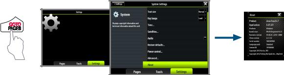
¼¼ Note: The About dialog above is an example only and may not match the software installed on your unit!
The manual will be continuously updated to match new software releases. The latest available manual version can be downloaded from www.bandg.com.
2 | |
Preface | Zeus Touch Operator Manual |

Contents
7 Introduction
7The Zeus Touch front panel and keys
8The Zeus Touch screen
10PDF viewer
11Basic operation
11The power key
11Using the touch screen
11Pages and panels
12The menus
12Dialog boxes
13Placing the cursor
13Positioning a Man Over Board mark
13Screen capture
14Charts
14The chart panel
14Chart scale
14Panning the chart
14The vessel symbol
15Using the cursor on the chart panel
16Positioning the chart on the panel
16The chart settings panel
18Chart overlay
18Selecting chart type
19Insight chart options
20Navionics chart options
23 Waypoints, routes & tracks
23Waypoints
24Routes
24Tracks
25The waypoints, route and tracks panels
26Navigating with the Zeus Touch
26The Goto menu
26Navigating on the chart
27Navigating with Autopilot
27Navigation settings panel
28Navigation panels
30 SailSteer screen
33 Using the Autopilot
33Safe operation with the Autopilot
33Activating the Autopilot
34The Autopilot panel
34 Selecting Autopilot modes
34 Autopilot mode overview
36 Controlling steering performance in automatic modes
36 Using the Autopilot in standby mode
36 Power steering (NFU)
36 Follow-up steering (FU)
36 AUTO mode (auto compass)
Contents | Zeus Touch Operator Manual |
| 3 |
40 NoDrift mode
40Navigating with the Zeus Touch
41Sailing with the Autopilot
43 Wind steering and navigation
43Using the Zeus Touch in an AP24/AP28 system
43Using the Autopilot in an EVC system
44The Autopilot settings panel
47Using the radar
47The radar panel
47The radar operational modes
47Using the cursor on the radar panel
48Optimizing the radar image
48Positioning the radar center
49Measuring range and bearing to a target
50Setting a guard zone around your vessel
51Radar options
52MARPA targets
54 Radar overlay
54Radar settings panel
54Mast rotation
55The echosounder
55Setting up the echosounder panel
56Zooming
57Adjusting color and gain settings
57Using the cursor on the echosounder panel
58Placing a mark on an echosounder image
58Measuring distance
58Pausing the echosounder
58Recording the echosounder data
59Echo options
60StructureScan™ overlay
60 The echosounder settings panel
62 StructureScan™
62Setting up the StructureScan™ image
63Zooming
64Adjusting the color settings
64Using the cursor on the StructureScan™ panel
64Placing a mark on a StructureScan™ image
65Measuring distance
65 Pausing StructureScan™
65Recording the StructureScan™ data
65Structure options
66StructureMap ™
66Activating Structure overlay
67StructureMap sources
67StructureMap tips
68Recording StructureScan data
68Using StructureMap with mapping cards
69Structure options
4 | |
Contents | Zeus Touch Operator Manual |
70The Instruments panels
70The dashboards
70Customizing the Instrument panel
71Data History
73Using AIS
73Target symbols
74Viewing information about AIS targets
74Vessel alarms
75The vessel settings panel
76AIS SART - Search And Rescue Transponder
77Audio
77 Enabling audio
77The audio media bar
78Setting up the SonicHub speakers
78Operating the audio source
79Audio playback
79Using the FM/AM radio
80Using Sirius radio
81Weather
81 GRIB Weather
84 SiriusXM™ weather (North America only)
87 Using Video
87 The video panel
87 Setting up the video panel
89 BEP CZone
89The BEP CZone panel
89CZone modes
90CZone system overview options
90The CZone info panel
91The alarm system
91 Type of messages
91Acknowledging a message
92The alarms dialog
93The Tools page
93 |
Vessels |
93 |
Alarms |
93Satellites
94Find
94 |
Waypoints/routes/tracks |
94 |
Trip Log |
94 |
Sun/moon |
94 |
Tides |
96 GoFree™ wireless
99 Operating the Zeus Touch with the wireless device
Contents | Zeus Touch Operator Manual |
| 5 |
101Customizing your system
101Page overview
101Create favorite pages
102Setting the appearance of the instrument bar
102Changing system settings
104Using the simulator
104Simulator mode
104Demo mode
104Selecting simulator source files
104Advanced simulator settings
105Maintenance
105 Preventive maintenance
105Simple maintenance procedures
105Software upgrades
106Trouble shooting
106Backing up your system data
107Menu and dialog overview
107Panel menus
108Goto menu
108 Settings dialogs
110 Index
6 | |
Contents | Zeus Touch Operator Manual |

1 |
Introduction |
The Zeus Touch front panel and keys |
4 |
STBY |
|
6 |
|
|||
AUTO |
|
7 |
|
||||
|
|
|
TER |
|
|
||
|
|
|
EN |
|
|
||
|
S |
H |
TO |
|
|
||
U |
|
|
|
||||
|
|
|
|
|
|||
P |
|
|
|
|
|
||
5 |
MARK |
GOTO |
8 |
|
|||
MENU |
PAGES |
|
|||||
|
|
|
|
|
|
||
|
|
IN |
OUT |
9 |
|
||
|
MOB |
MOB |
|
||||
|
|
|
|
|
|
|
|
|
|
|
|
|
|
10 |
|
1 |
|
|
|
|
2 |
2 |
3 |
1Touch screen
2Card reader door
3Micro-SD Card reader
Used for optional Navionics or InsightHD chart data, software updates, transfer of user data and system backup.
4STBY / AUTO key
Used for Autopilot operation.
5MARK / MENU key
A short press displays the active panel’s menu. A double press displays the Settings menu.
A long press places a waypoint at the vessel’s position.
6X key
Used to exit dialogs, to return to previous menu level and to remove the cursor from the screen on chart, radar and echosounder panels.
7Rotary knob
Used for zooming chart and for scrolling through menus. Press rotary knob to confirm selection.
8GO TO / PAGES key
A short press displays the Pages overview panel (Home page). Repeated short presses toggles between Pages overview, Tools and Settings panels.
A long press displays the Goto menu.
9IN / OUT / MOB key
Zoom key for chart, radar and echosounder panels. A simultaneous press on both key ends will position a Man Over Board (MOB) mark at vessel’s position.
10Power key
A long press turns the unit ON/OFF.
A short press brings up the backlight and radar standby control dialog. Repeated short presses toggles between preset brightness levels.
Introduction | Zeus Touch Operator Manual |
| 7 |

The Zeus Touch screen
1 2 3
4 |
5 |
6 |
7 |
8 |
1Instrument bar
Navigation and sensor info can be viewed in a user configurable instrument bar on top of your pages.
2Panel button
You can tap the text on this area to end an ongoing operation, e.g. to remove the cursor from the screen, to end route editing and to stop measuring distance.
3Dialogs
Dialogs are used for user input or for presenting information to the user.
A dialog may be presented in full-screen or as a popup dialog in the centre of the screen. Depending on type of information or entry, different keys are used to confirm, cancel and close the dialog.
A dialog can always be closed by tapping the  in the upper right corner or by pressing the X key.
4Menus
Different menus are available to select options and to configure your system. A menu is displayed by pressing the MENU key, by tapping the MENU panel button, or by tapping and holding on the touchscreen.
5Application panels
Each application connected to the system is presented on panels, and you can have several panels depending on screen size:
|
• |
T7 |
2 panels |
|
|
• |
T8 and T12: |
4 panels |
|
|
|
|
|
|
|
|
|
|
|
1-panel page |
2-panels page |
3-panels page |
4-panels page |
8 | |
Introduction | Zeus Touch Operator Manual |

The system includes the following page groups, which each have a pre-configured combination of panels:
Icon |
Description |
Main page |
|
|
|
|
Instruments with configurable live data |
|
|
from system internal, and external sources |
Instruments |
|
such as engines |
|
|
|
|
|
Echosounder |
Echosounder |
|
|
|
|
Live video |
Video |
|
|
|
|
Navigation information |
Steering |
|
|
|
|
Insight or Navionics charts, depending on |
Chart |
|
region |
|
|
|
|
|
|
|
|
Radar |
Radar |
|
|
|
The main page in each group is a full size panel. All pre-configured pages, except the main page for the group, can be modified by the user.
In addition to these panels the following applications can be connected and displayed on other panels:
Panel |
Description |
|
|
AIS |
AIS information as overlay on chart and radar panels |
|
|
Weather |
Sirius (North America only) weather graphics and data as overlay on |
|
chart panel |
|
|
Audio |
Satellite radio (North America only) and SonicHub functions as a panel |
|
along the bottom of a page |
|
|
StructureMap |
Overlays sidescan images over the chart |
|
|
6MENU panel button
Tapping this panel button will display the menu for active panel. Same function as pressing the MENU key.
7Alarm message
The system will continuously check for dangerous situations and system faults while the system is running. When an alarm situation occurs, an Alarm dialog will pop up.
If you have enabled the siren, an audible alarm will be activated when an alarm situation occurs.
8The Control pages
The Control pages give access to page selection, tools and settings.
The Pages overview panel (Home) is displayed by pressing the PAGES key. Repeated presses on this key will toggle between the control panels.
You can also switch between the control panels by dragging your finger horizontally on the screen.
Introduction | Zeus Touch Operator Manual |
| 9 |
All control panels and sub-panels are always full screen, and they will open on top of your previous page. When you close one of these panels the display will return to last active page.
Pages overview (Home page) |
Tools |
Settings |
Pages overview
The pages overview panel is accessed from any operational mode by pressing the PAGES key.
The panel includes 6 page group icons together with shortcuts to the Autopilot panel, to a combined chart/echo panel, and to the SailSteer panel.
¼¼ Note: To see an Autopilot panel an Autopilot computer must be connected to the system. Similarly a StructureScan module must be available on the network to use StructureScan.
Tools
The tools panel include options that are not specific to any panel e.g. status regarding vessels, alarms, satellites, sun/moon and tides. Also included are waypoints, routes and tracks library, trip log, find function and files.
If a CZone system is connected, this function is accessed from the Tools panel.
Settings
The Settings panel gives access to system and vessel setup, application settings, and to the simulator.
PDF viewer
Use the PDF viewer to read manuals and other PDF files on the Zeus Touch display. The manuals can be read from an inserted Micro-SD card or copied to the unit’s internal memory and read from there.
Zeus Touch manuals can be downloaded from www.bandg.com.
Use the keys and softkeys to maneuver in the pdf file as below:
Search, Page Up/Down |
Tap the relevant softkeys |
|
|
Scroll pages |
Turn the rotary key |
Panning on page |
Tap and drag finger on screen in any direction |
|
|
Zoom In/Out |
Press IN/OUT keys |
|
|
Exit the pdf viewer |
Press the X key |
10 | |
Introduction | Zeus Touch Operator Manual |
2
Advanced power control
The Zeus Touch can be wired and configured to control the power of displays and compatible devices. See
the Zeus Touch Installation manual for more information.
Basic operation
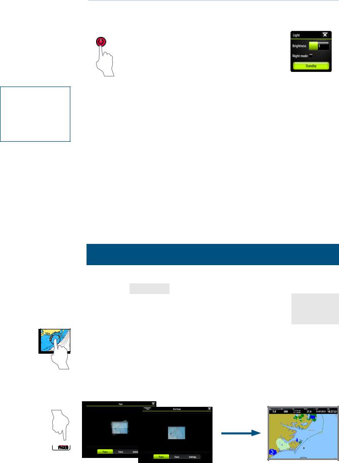
The power key
|
|
|
|
• |
Press and hold: |
Turn unit on/off |
|
|
|
|
|
|
|
|
|
|
|||
|
|
|
|
• |
|
Display dialog for light adjustment, |
|
|
|
|
|
|
|
|
|
|
|
||
|
|
|
|
Single press: |
standby mode and radar standby/ |
|
|
|
|
|
|
|
|
|
|
transmit |
|
|
|
|
|
|
|
|
|
|
|
|
|
|
|
|
|
• |
Repeated |
Toggle preset brightness levels (10 |
|
|
|
|
|
|
|
|
presses: |
- 6 - 3- 1) |
|
|
|
|
|
|
|
|
|
|
|
||
|
|
|
|
|
|
|
|
|
|
¼¼ Note: If the power key is released before shut-down is completed, the power off is cancelled.
A night mode which optimizes the color palette for low light conditions, is included.
¼¼ Note: Details on the chart may be less visible when the Night mode is selected!
When in Standby mode, the backlight for touch screen and keys are turned off to save power. The system will continue to run in the background and will notify you if an alarm situation should occur.
You return from Standby mode to normal operation by pressing the power key.
If the radar is transmitting you can set it to standby mode from within the Light dialog.
Using the touch screen
Basic touchscreen operation on the different panels is shown in the table below.
The panel sections later in this manual have more information about panel specific touch screen operation.
Operation |
Menu/ |
|
|
Panels |
|
|
Dialogs |
Chart |
|
Echo |
|
Radar |
|
|
|
|
||||
|
|
|
|
|
|
|
Tap |
Select/ |
|
|
Place cursor |
|
|
toggle item |
|
|
|
|||
|
|
|
|
|
|
|
Tap and hold |
|
|
Display menu for active panel |
|
||
|
|
|
|
|
|
|
|
Adjust slider |
Pan chart |
|
Pan echo history |
|
|
Drag |
value |
|
|
|
||
(any direction) |
(horizontal movement) |
|
|
|||
|
|
|
||||
|
Scroll dialog |
|
|
|||
|
|
|
|
|
|
|
¼¼ Note: When tapping and holding, a circle will spin around the tap point. Hold till action circle has completed or until the action is confirmed by a second beep.
Pages and panels
Select pages
You access a page group and then select the page to display from the PAGES panel.
GOTO
PAGES
Basic operation | Zeus Touch Operator Manual |
| 11 |

Select active panel
In a split screen you have multiple panels, but only one panel can be active at a time. You will only be able to access the context menu of the active panel. The active panel is outlined with a coloured border.
You can switch between active panels by tapping the required panel.
The menus
Menus are used to operate the system and to adjust settings.
You display a menu by:
MARK |
• Pressing the MENU key |
|
MENU |
||
|
• |
Tapping the MENU panel button |
|
• |
Pressing and holding on active panel |
•You select a menu item and toggle on/off menu check boxes by tapping selected item.
•You adjust slide bar values by tapping the item and then dragging your finger on the slide bar. The value can also be adjusted by turning the rotary knob.
•Drop-down listings are selected by tapping the item and then the selected value.
|
|
|
|
|
|
|
|
|
|
|
|
|
|
|
|
|
|
|
|
|
|
|
|
|
|
|
|
|
|
|
|
|
|
|
|
|
|
|
|
|
|
|
|
|
|
|
|
|
|
|
|
|
|
|
|
|
|
|
|
|
|
|
|
|
|
|
|
|
|
|
|
|
|
|
|
|
|
|
|
|
|
|
|
|
|
|
|
|
|
|
|
|
|
|
|
|
|
|
|
Check box |
|
|
|
Slide bar |
|
|
Drop-down listing |
|
|
You can also operate a menu by using the rotary knob to select menu item, and then pressing the knob to confirm your selection.
By pressing the X key the menu will return to previous menu level, and then exit. You can also close a menu by tapping the screen outside the menu area.
Dialog boxes
You select entry fields and keys in a dialog box by tapping the screen or by using the rotary knob. You can only enter information when a field is selected and highlighted.
Some dialog listings might extend beyond the screen area. These dialogs will include a scroll indicator, and you scroll by dragging the list or turning the rotary knob.
Numeric and alphanumeric keyboards will automatically be displayed when required for entering user information in dialogs.
A virtual keyboard is operated by tapping the virtual keys.
A dialog is closed by tapping the  in the upper right corner or by pressing the X key.
12 | |
Basic operation | Zeus Touch Operator Manual |
MARK |
GOTO |
MENU |
PAGES |
IN |
OUT |
MOB |
MOB |
Placing the cursor
The cursor is by default not shown on any panel.
You tap the screen to place the cursor on a Chart, Radar, StructureScan or Echosounder panel. The cursor information window will show position coordinates at the cursor position, and range and bearing to the vessel.
On an Echosounder panel, the cursor information window will include the depth at cursor position.
Further use of the cursor is described in the Chart, Radar and Echosounder sections.
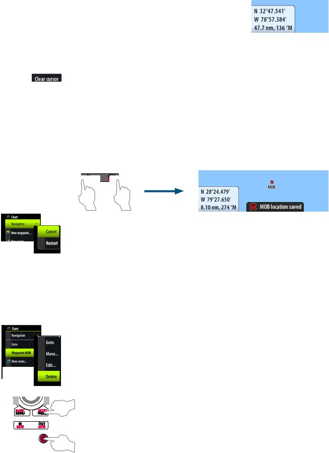
To remove the cursor and cursor window from the panel, press the X key or tap the Clear cursor panel button.
Positioning a Man Over Board mark
If an emergency man over board situation should occur, you can position a Man Over Board mark at the vessel’s current position by pressing the two MOB keys simultaneously.
When you activate the MOB function the following actions are automatically performed:
•a MOB mark is positioned at the vessel’s position
•the display switches to a zoomed chart panel, centered on vessel position
•the Zeus Touch creates an active route to the MOB mark
IN |
OUT |
MOB |
MOB |
+
Cancel navigation
The Zeus Touch will continue navigating towards the MOB point until the waypoint is reached or until you select to stop this navigation.
Positioning multiple Man Over Board marks
Once the MOB function has been initialized, pressing the MOB keys again will place a new MOB waypoint on the chart. Continued presses of the MOB keys will place more MOB waypoints.
¼¼ Note: The vessel will always continue to navigate towards the initial MOB mark until the waypoint is reached, or until you stop the navigation. Navigation to subsequent MOB marks will need to be done manually. (See navigating on the chart section for more details).
Delete a MOB mark
A MOB mark is deleted by selecting the MOB mark and then activating the menu. A MOB can also be deleted as described in page 23 .
Screen capture
Simultaneously press and hold the GOTO/PAGES and power keys to take a screenshot.
By default, screen captures are saved to internal memory. From the internal memory they can be copied to another folder or Micro-SD card via the Files menu.
Basic operation | Zeus Touch Operator Manual |
| 13 |
3 |
Charts |
|
|
|
|
|
|
||||||||||||||||||||
|
|
|
|
|
|
|
|
|
|
|
|
|
|
|
|
|
|
|
|
|
|
|
|
|
|
|
|
The chart function displays your vessel’s position relative to land and other chart objects. |
|||||||||||||||||||||||||||
On the panel you can plan and navigate routes, place waypoints, overlay a radar image or |
|||||||||||||||||||||||||||
weather information, and display AIS targets. |
|
|
|
|
|
|
|||||||||||||||||||||
|
The Zeus Touch has different embedded cartography depending on region. Units sold |
||||||||||||||||||||||||||
|
in America will include Insight cartography, while units sold in other regions will have |
||||||||||||||||||||||||||
|
embedded Navionics coastal (Silver) cartography split by region. All units will support |
||||||||||||||||||||||||||
|
Navionics Platinum Plus and TurboView via Micro-SD Card slot accessible from the front of the |
||||||||||||||||||||||||||
|
unit. |
|
|
|
|
|
|
||||||||||||||||||||
|
Charts are shared over the network, so only one chart card per boat is required. |
|
|
|
|
|
|
||||||||||||||||||||
|
The first part of this section describes how to use the charts, and is common to both Insight |
||||||||||||||||||||||||||
|
and Navionics. Chart options depend on which cartography is in use on the unit. These are |
||||||||||||||||||||||||||
|
covered in a separate section. |
|
|
|
|
|
|
||||||||||||||||||||
|
The chart panel |
|
|
|
|
|
|
||||||||||||||||||||
|
|
|
|
|
|
|
|
|
|
|
|
|
|
|
|
|
|
|
|
|
|
|
|
|
|
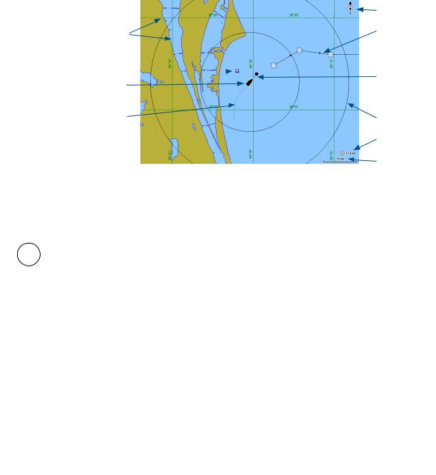
North indicator |
|
|
|
|
|
|
|
|
|
|
|
|
|
|
|
|
|
|
|
|
|
|
|
|
|
|
|
||
|
|
|
|
|
|
|
|
|
|
|
|
|
|
|
|
|
|
|
|
|
|
|
|
|
|
||
|
|
Grid lines * |
|
|
|
|
|
|
|
|
|
|
|
|
|
|
|
Route * |
|||||||||
|
|
|
|
|
|
|
|
|
|
|
|
|
|
||||||||||||||
|
|
|
|
|
|
|
|
|
|
|
|
|
|
|
|
|
|
||||||||||
|
|
Waypoint * |
|
|
|
|
|
|
|
|
|
|
|
|
|
|
|
|
|
|
|
|
Extension line * |
||||
|
|
|
|
|
|
|
|
|
|
|
|
|
|
|
|
|
|
|
|
|
|
||||||
|
|
|
|
|
|
|
|
|
|
|
|
|
|
|
|
|
|
|
|
|
|
||||||
|
|
|
|
|
|
|
|
|
|
|
|
|
|
|
|||||||||||||
|
|
|
|
|
|
|
|
|
|||||||||||||||||||
|
|
|
|
|
|
|
|
|
|
|
|
|
|
|
|
|
|
|
|
|
|
||||||
|
|
Vessel |
|
|
|
|
|
|
|
|
|
|
|
|
|
|
|
|
|
|
|
|
|
|
|||
|
|
|
|
|
|
|
|
|
|
|
|
|
|
|
|
|
|
|
|
||||||||
|
|
|
|
|
|
|
Range rings * |
||||||||||||||||||||
|
|
|
|
|
|
|
|
|
|
|
|
|
|
|
|
|
|
|
|
|
|
||||||
|
|
Track * |
|
|
|
|
|
|
|
|
|
|
|
|
|
|
|
|
|
|
|
||||||
|
|
|
|
|
|
|
|
||||||||||||||||||||
|
|
|
|
|
|
|
|
|
|
|
|
|
|
|
|
|
|
|
|
|
|
|
|
Range rings |
|||
|
|
|
|
|
|
|
|
|
|
|
|
|
|
|
|
|
|
|
|
|
|
|
|||||
|
|
|
|
|
|
|
|
|
|
|
|
|
|
|
|
|
|
|
|
|
|
|
|||||
|
|
|
|
|
|
|
|
|
|
|
|
|
|
|
|
|
|
|
|
|
|
|
|
|
|
|
interval * |
|
|
|
|
|
|
|
|
|
|
|
|
|
|
|
|
|
|
|
|
|
|
|
|
||||
|
|
|
|
|
|
|
|
|
|
|
|
|
|
|
|
|
|
|
|
|
|
|
|
Chart range scale |
|||
|
|
|
|
|
|
|
|
|
|||||||||||||||||||
|
* Optional chart items |
|
|
|
|
|
|
||||||||||||||||||||
|
¼¼ Note: You turn the optional images on/off individually. See “The chart settings panel” on |
||||||||||||||||||||||||||
|
|
page 16. |
|
|
|
|
|
|
|||||||||||||||||||
|
or |
IN |
OUT |
MOB |
MOB |
Chart scale
You zoom in and out on the chart by using the IN/OUT keys or by using the rotary knob.
Chart range scale and range rings interval (when turned on) will be shown in the lower right corner of the chart panel.
Panning the chart
You can move the chart in any direction by tapping the screen and dragging your finger in the selected direction.
Pressing X key will remove the cursor from the panel, and the chart center will be positioned at the vessel.
The vessel symbol
Position and orientation
When a GPS and a suitable heading sensor are connected to the system, the vessel symbol indicates vessel position and heading.
Without a heading sensor fitted, the vessel icon will orientate itself using COG (Course over Ground). If no GPS is available the vessel symbol will include a question mark.
14 | |
Charts | Zeus Touch Operator Manual |

Using the cursor on the chart panel
The cursor is by default not shown on the chart panel.
When you tap the screen, the cursor will become visible and the cursor position window will be activated. When the cursor is active, the chart will not pan or rotate to follow the vessel.
To remove the cursor and cursor window from the panel, press the X key or tap the Clear cursor panel key.
Pressing the X key repeatedly will toggle the chart center between the vessel and the cursor position.
Displaying information about chart and chart objects
When you tap a chart item, a waypoint, a route or a target, basic information for the selected item will be displayed.
By tapping and holding or by pressing the rotary knob when a chart item is selected, all available information for that item will be shown.
The information can also be displayed by using the menu.
¼¼ Note: Popup information has to be enabled to see basic item information.
If the cursor is not active, available information for objects close to the vessel can be displayed.
If no information is available, the info menu item will not be shown.
Placing waypoints
You place a waypoint by tapping the chart panel on the selected position and then activating the menu.
Creating routes
You can quickly create routes by tapping the chart panel.
1.Activate the menu
2.Tap the screen to position the first routepoint, and then continue tapping the screen to place the remaining routepoints
3.Save the route by tapping the Finish editing panel button or by activating the menu
Dragging waypoints
1.Tap the waypoint to make it active
2.Drag the waypoint to the new position
The waypoint position will be automatically saved.
Measuring distance
The cursor can be used to measure the distance between your vessel and a selected position, or between 2 points on the chart panel.
1.Tap the screen on the place to where you want to measure the distance from the vessel
2.Start the measure function from the menu
•A line will be drawn from the vessel center to the cursor position and a marker will be placed at each end of the measuring line. The distance will be listed in the Cursor Information window.
¼¼ Note: You can reposition the measuring line by moving either of the markers on the chart by dragging them to a new position.
Charts | Zeus Touch Operator Manual |
| 15 |
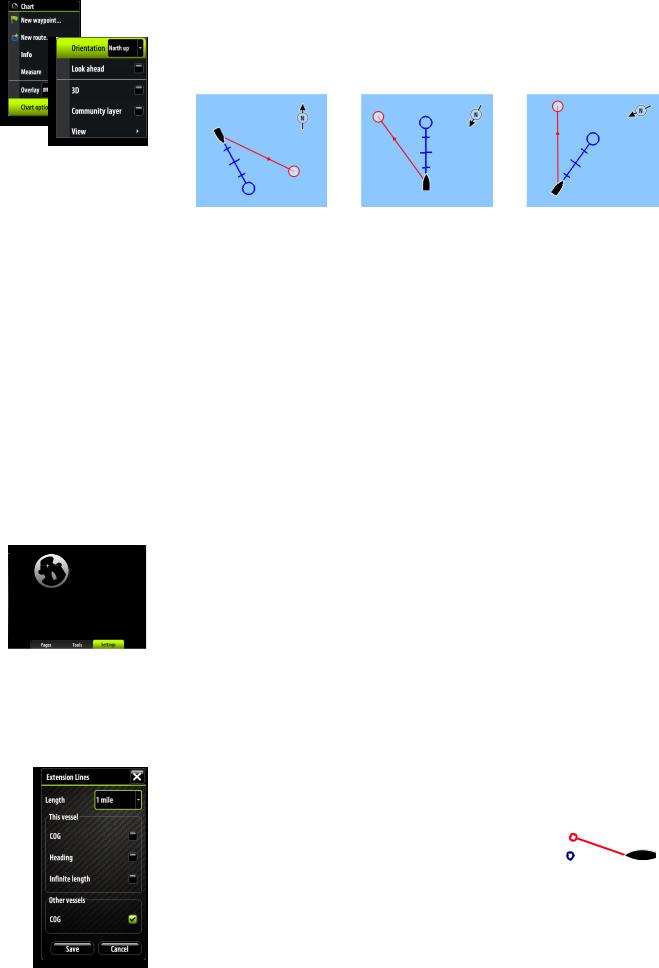
Positioning the chart on the panel
Chart orientation
Several options are available for how the chart is rotated in the panel. The chart orientation symbol in the panel’s upper right corner indicates the north direction.
North up |
Heading up |
Course up |
North up
Displays the chart with the north direction upward. Corresponds to the usual orientation of nautical charts.
Heading up
Displays the chart with the vessel’s heading directly up on the chart image. Heading information is received from a compass. If heading is not available, then the COG from the GPS will be used.
Course up
Rotates the chart in the direction of the next waypoint when in navigation mode. This option works only when there’s an active route. If no route is active the heading up orientation will be used until a route is made active.
Look ahead
This option centres the chart slightly forward of your vessel so that you can maximize your view ahead.
The chart settings panel
Settings and display options made in the Chart settings page are common for all chart panels. For optional chart panel settings, refer the illustration on page 14.
3D boat selection
Determines which icon to use on 3D charts. See “The chart panel” on page 14
Range Rings
Turns on/off range rings on the chart.
The range rings can be used to present the distance from your vessel to other chart objects. The range scale is set automatically by the system to suit the chart scale.
The vessels’ extension lines
Sets the length of the extension lines for your vessel and for |
|
|
|
|
other vessels shown as AIS targets. |
|
|
|
|
|
COG |
|||
The length of the extension lines are either set as a fixed |
|
|||
|
|
|
||
distance, or to indicate the distance the vessel will move in the |
|
|
|
|
Heading |
||||
selected time period. |
||||
Own vessel heading is based on information from the active |
|
|
|
|
|
|
|
||
heading sensor and COG from active GPS sensor. |
|
|
|
|
For other vessels COG data is included in the message received from the AIS system.
16 | |
Charts | Zeus Touch Operator Manual |

Laylines
When navigating to a waypoint you can configure laylines on the chart to aid navigation. These lines can be set from the vessel, waypoint or both. The laylines convey the vessels present laylines varying with wind, tide and tacking angle.
To configure the laylines go to the laylines dialog.
|
Laylines |
Layline Options |
|
|
|
Boat |
Layline from vessel. The length can be set to 1, 10 or 100 miles. |
|
|
Mark |
Layline from mark/waypoint. The length can be set at 1, 10 or |
|
100 miles. |
|
|
Tidal Flow Correction |
Tidal flow correction will calculate the tidal flow and offset the |
|
laylines accordingly. |
|
|
Overlapped |
When selected the laylines will extend beyond the tack/gybe |
|
intersection. |
|
|
True Wind Angle |
There are 3 sources available for true wind angle (TWA). You can |
|
choose between Polar, Actual or Manual. |
|
|
Polar |
Takes the target TWA from your polar table. (Polar table is |
|
available in Hercules Performance and Hercules Performance |
|
Motion only). |
|
|
Actual |
Takes the current value of true wind angle (TWA). |
|
|
Manual |
Manually input the upwind and downwind numbers into the |
|
dialogue boxes. |
|
|
Limits |
When selected will show a dotted line indicating the minimum |
|
and maximum tack/gybe time period either side of the layline. |
|
This can be set from 5 to 30 minutes. |
|
|
Synchronize 2D/3D chart
Links the position shown on one chart with the position shown on the other chart when a 2D and a 3D chart are shown side by side.
Pop-up information
Selects whether basic information for chart items shall be displayed when you tap the item.
Grid lines
Turns on/off viewing of longitude and latitude grid lines on the chart.
Course Highway
Turn course highway on/off
Waypoints, Routes, Tracks
Turns on/off displaying of these items on chart panels.
Charts | Zeus Touch Operator Manual |
| 17 |
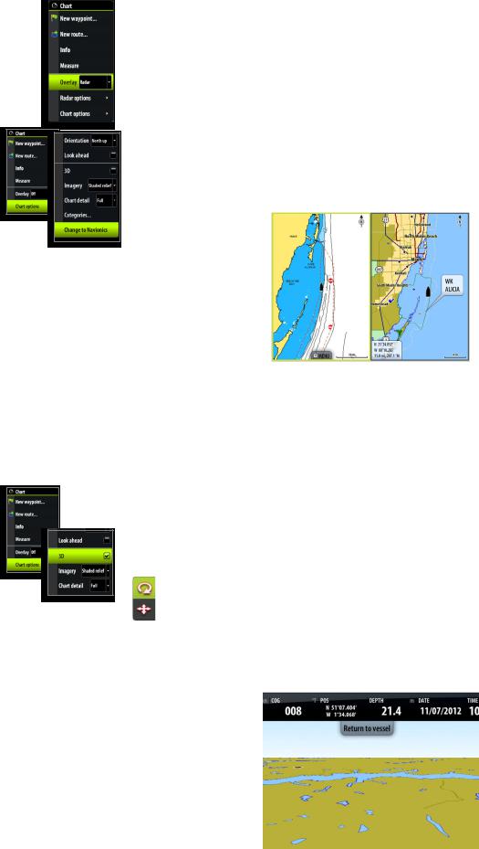
Chart overlay
Radar, structureMap and weather information can be displayed as overlay on your chart panel.
When an overlay is selected, the chart context menu will be expanded to include basic function for the selected overlay.
Radar, weather, StructureScan functions are described in separate sections in this manual.
Selecting chart type
Chart type is selected from the chart options menu, and the selection is set individually for each chart panel.
If you have Navionics charts available in the Micro-SD card slot, you can show Navionics and Insight charts simultaneously in a split screen.
Chart data
The Zeus Touch can use Navionics Platinum Plus and TurboView via Micro-SD Card Slot accessible from the front of the unit.
Charts are shared over the network, so only one chart card per boat is required.
¼¼ Note: The system will not automatically switch to embedded cartography if the micro-SD card is removed. A low-resolution chart will be displayed until you re-insert the micro-SD card or manually switch back to embedded cartography.
3D charts
There are two 3D view options available:
•Rotate - default view keeping the boat in center on the chart panel
•Pan - allows you to move the 3D chart view away from the vessel
Toggle between these two options by tapping the pan and rotate icons. The active option is indicated with the coloured icon.
Return to default Rotate view by tapping the Return to vessel panel button.
18 | |
Charts | Zeus Touch Operator Manual |

Rotating the 3D chart
In rotate view mode the camera position is fixed, and the camera can only be rotated and tilted.
By default the vessel’s position will be in the center of the view, or towards the bottom if Look Ahead is enabled. The camera angle is as seen from your eye position, looking toward the vessel. The vessel’s rotation on the chart is defined by the chart orientation settings.
You can change the camera’s tilt angle by dragging your finger on the screen with vertical motions. You rotate the camera around its own vertical axis by dragging your finger horizontally on the screen.
¼¼ Note: You can only rotate the camera if you have panned away from default vessel position, that is when the Return to vessel panel button is available.
Panning
The Pan option allows you to view the entire 3D chart, regardless of vessel position.
Move the camera away from the vessel and around in the chart by dragging your finger on the screen. When you remove your finger from the screen the view will remain in the selected position.
The camera’s tilt angle is as set in Rotate view.
Zooming
Zoom in and out on a 3D chart by using the IN/OUT keys or the rotary knob.
Insight chart options
Chart orientation
See page 16.
Look ahead
This option centres the chart slightly forward of your vessel so that you can maximize your view ahead.
3D
See page 1620, 3D charts.
Chart imagery style
The charts can be displayed in two different imagery styles, either as 2D basic mapping style, or with shaded relief presenting chart including terrain imaging.
2D |
Shaded relief |
Charts | Zeus Touch Operator Manual |
| 19 |
Chart detail
Low
This is the basic level of information that cannot be removed, and includes information that is required in all geographic areas. It is not intended to be sufficient for safe navigation
Medium
This is the minimum information sufficient for navigation
Full
This is all available information for the chart in use
Categories
Insight charts includes several categories and sub-categories that you can turn on/off individually depending on which information you want to see on your display.
Navionics chart options
Chart orientation and Look ahead
See page 16.
3D
See page 20, 3D Charts.
Community layer
Community Layer enables the display on the chart of user-generated information and edits that have been uploaded to Navionics Community and made available in Navionics charts.
For more information refer to the Navionics information included with your chart, or to Navionics website: www.navionics.com/product/water/plotter-charts.
Chart view
Chart shading
Shading adds terrain information to the chart.
Traditional 2D chart |
Chart with shading |
20 | |
Charts | Zeus Touch Operator Manual |
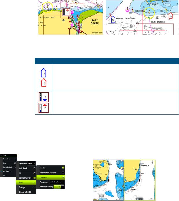
Dynamic tides and currents
Shows tides and currents with a gauge and an arrow instead of the diamond icons used for static tides and current information.
The tide and current data available in Navionics charts are related to a specific date and time. The Zeus Touch animates the arrows and/or gauges to show the tides and currents movement over time.
Dynamic Tide information |
Dynamic Current information |
The following icons and symbology are used:
Icons Description
Current rate.
The arrow length depend on the rate, and the symbol is rotated according to flow direction. Flow rate is shown inside the arrow symbol.
Red symbol used when current speed is ascending,- blue symbol when current speed is decreasing.
Tide height.
The gauge have 8 labels and is set according to absolute max/min value of the evaluated day.
Red arrow used when tide is growing,- blue arrow when tide is decreasing.
¼¼ Note: All numeric values are shown in the relevant system units (unit of measurement) set by user.
Easy View
Easy View is a magnifying feature which increases the size of chart items and text making key features of a chart more visible and easier to read and understand.
¼¼ Note: There is no indication on the chart showing that this feature is active.
|
|
|
|
|
| 21 |
|
|
|
|
|
|
|
|
|
|
|
|
|
|
|
|
|
|
|
|
|
|
|
|
|
|
|
|
|
|
|
|
|
|
|
|
|
|
|
|
|
|
|
|
|
|
|
|
|
|
Charts | Zeus Touch Operator Manual |
|||
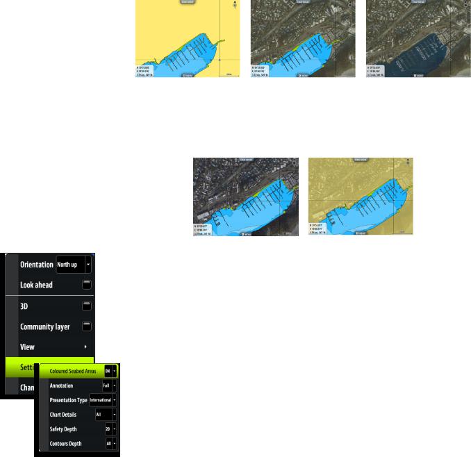
Photo overlay
Photo overlay enables you to view satellite photo images of an area as an overlay on the chart. The availability of such photos is limited to certain regions.
You can view photo overlays in either 2D or 3D modes.
No Photo overlay |
Photo overlay, land only |
Full Photo overlay |
Photo transparency
The Photo transparency sets the opaqueness of the photo overlay. With minimum transparency settings the chart details will be almost hidden by the photo.
Minimum transparency |
Transparency value = 10 |
Navionics Fish’n Chip
Zeus Touch supports Navionics Fish’n Chip (US only) chart feature.
For more information, see www.navionics.com.
Navionics chart settings
Colored Seabed Areas
Used for displaying different depth areas in different colors.
Annotation
Determines what area information, such as names of locations and notes of areas, is available on display.
Presentation type
Provides marine charting information such as symbols, colors of the navigation chart and wording for either International or US presentation types.
Chart details
Provides you with different levels of geographical layer information.
Safety depth
The Navionics charts use different shades of blue to distinguish between shallow and deep water.
The safety depth sets the limit for which depths that shall be drawn without blue shading.
¼¼ Note: The built in Navionics database features data down to 20 m, after which it is all white.
Contours depth
Determines which contours you see on the chart down to the selected safety depth value.
22 | |
Charts | Zeus Touch Operator Manual |

4 |
Waypoints, routes & tracks |
|
|
|
|
Waypoints |
||
A waypoint is a user generated mark positioned on a chart, on a radar image or on an |
||
echosounder image. Each waypoint has an exact position with latitude and longitude |
||
coordinates. A waypoint positioned on an echosounder image, will in addition to position information have a depth value.
A waypoint is used to mark a position you later may want to return to. Two or more waypoints can also be combined to create a route.
Positioning waypoints
Placing a waypoint at vessel position
You can position a waypoint at the vessel position from any panel by pressing and holding the MARK / MENU key.
Using the cursor to position waypoints
On chart, echosounder and StructureScan panels you can place a waypoint on a selected position by tapping the screen and then activating the panel menu.
Edit waypoints
A selected waypoint can be deleted or edited on a chart panel from the menu, or from the waypoint dialog.
You can quickly move a waypoint on a chart panel by tapping the desired new location on the screen.
Using the edit waypoint dialog
This dialog is activated by tapping the waypoint and then activating the menu, or pressing the rotary knob when the waypoint is selected.
The dialog can also be activated from the Waypoint list. See “The waypoints, route and tracks panels” on page 25.
Waypoint alarm settings
You can set an alarm radius for each individual waypoint you create.
¼¼ Note: The waypoint radius alarm must be toggled ON in the
alarm panel to activate an alarm when your vessel comes within the defined radius.
Waypoints, routes & tracks | Zeus Touch Operator Manual |
| 23 |

Moving a waypoint by tapping the screen
1.Select the waypoint by tapping it
2.Activate the menu and select the move option
-- The waypoint icon will change to indicate moving mode
3.Tap on the chart panel to select a new position
4.Confirm the new position by pressing the rotary knob, tapping the panel key or by using the options in the menu
Routes
A route consists of a series of routepoints entered in the order that you want to navigate them.
When you tap on an existing route, it will turn blue and the route name will be displayed.
Creating new routes
1.Select the new route option from the menu
2.Tap the panel to position the first waypoint
3.Continue tapping the chart panel until all routepoints are positioned
-- A waypoint can easily be re-positioned by dragging it to the new position
4.Save the route by tapping the Finish editing panel button or by using the options in the menu
The route can also be created from the Routes panel described later in this section.
Edit a route
A route and a waypoint can only be edited from the chart panel when the item is selected.
1.Tap the route to make it active
2.Activate the menu and select the route and edit option
3.Tap the panel to add a new routepoint
•If you tap on a leg a new point will be added between existing routepoints
•If you tap outside the route the new routepoint will be added after the last point in the route 4. Drag a routepoint to move it to a new position
5. Save the route by tapping the panel button or by using the options in the menu
¼¼ Note: a single routepoint can be moved by tapping the routepoint and then selecting the move option in the menu.
Tracks
A track is a graphical presentation of the historical path of the vessel, allowing you to retrace where you have travelled. A track can be converted to a route in the Tracks panel, as described later in this section.
From the factory, the system is set to automatically draw a track. The system will continue to record the track until the track length reaches the maximum trail point setting, and will then automatically begin overwriting the oldest track points.
The automatic tracking function can be turned off from the Tracks panel described later in this section.
24 | |
Waypoints, routes & tracks | Zeus Touch Operator Manual |
Creating a new track
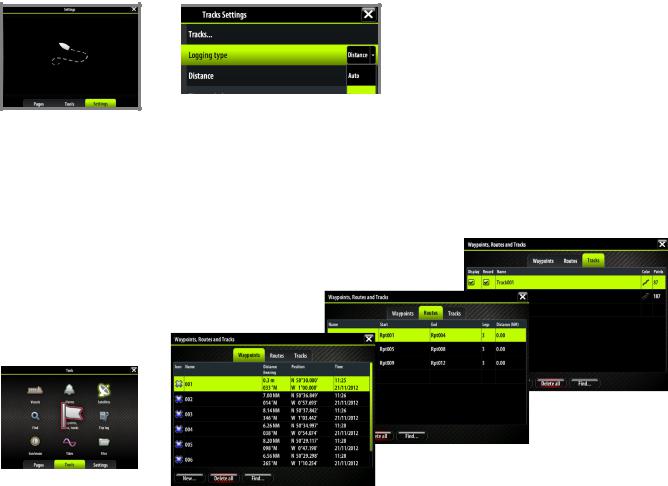
You define the track settings and start the new track from the Tracks Settings dialog described below.
Track settings
The track is made up of a series of track points connected by line segments whose length depends on the frequency of track recording.
You can select to position track points based on time settings, distance, or by letting the Zeus Touch system position a waypoint automatically when a course change is registered.
¼¼ Note: The Tracks option must also be turned ON in the chart settings to be visible.
The waypoints, route and tracks panels
The Waypoints, Routes and Tracks panels gives access to advanced edit functions and settings for all these items available on your system.
The edit and settings options are accessed from the menu or by using the dialog buttons when one of the items is selected.
|
|
|
|
|
|
|
|
|
|
|
|
|
|
|
|
|
|
|
|
|
|
|
|
|
|
|
|
|
|
|
|
|
|
|
|
|
|
|
|
|
|
|
|
|
|
|
|
|
|
|
|
|
|
| 25 |
|
|
|
|
|
|
|
||
|
|
|
Waypoints, routes & tracks | Zeus Touch Operator Manual |
||||
5 |
Navigating with the Zeus Touch |
|
|
|
|
The navigation function included in the Zeus Touch allows you to navigate towards the cursor |
||
position, a waypoint or along a predefined route. |
||
For information about positioning waypoints and creating routes, refer “The waypoints, route |
||
and tracks panels” on page 25. |
||
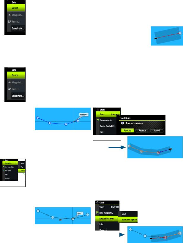
The Goto menu
You can start navigation from any panel by using the Goto menu, displayed by pressing and holding the GO TO / MENU key.
¼¼ Note: The Goto cursor option will only be available when the cursor is active on a Chart, Radar or Echosounder panel.
When the Zeus Touch starts navigating, the cross track limits will be indicated on the chart. See “Navigation settings panel” on page 27.
Navigating on the chart
You can start navigating on the chart from the chart menu and from the Goto menu. The
description and the illustrations below show use of the Goto menu, activated by pressing and holding the PAGES key.
Navigate to cursor position
You can start navigating towards a point on the chart by tapping the selected destination, activating the Goto menu and selecting the cursor option.
Navigate a route
You can start navigating a route by tapping the route and then activating the Goto menu.
When route navigation is started, the Goto menu will expand showing options for skipping a waypoint, or for restarting the route from current vessel position.
Selecting start point
You can navigate a route, starting from any waypoint, by positioning the cursor over the selected waypoint and activating the Goto menu.
26 | |
|
|
|
|
|
|
|
|
|
|
|
|
|
|
|
|
|
|
|
|
|
|
|
|
|
|
|
|
|
Navigating with the Zeus Touch | Zeus Touch Operator Manual |
|||||
Cancel navigation
You cancel navigation from the Goto menu or the chart panel menu.
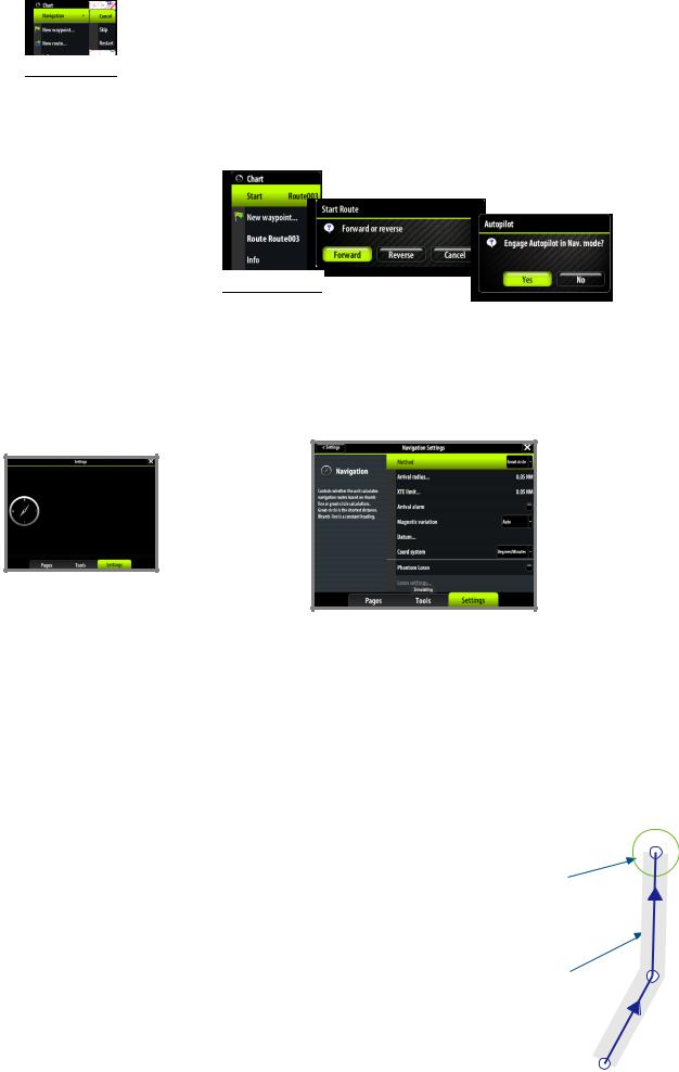
Navigating with Autopilot
If an Autopilot computer is connected to the system, Autopilot functionality will be included in the Zeus Touch.
When you start navigation on a system with Autopilot functionality, you will be prompted to set the Autopilot to navigation mode.
If you choose not to engage the Autopilot, the Autopilot can later on still be set to navigation mode from the Autopilot menu.
For more information about Autopilot functionality see “Navigating with Autopilot” on page 27.
Navigation settings panel
Navigation method
Different methods are available for calculating the distance and bearing between any two points on a chart.
The great-circle route is the shortest path between two points. However, if you are to travel along such a route, it would be difficult to steer manually as the heading would constantly be changing (except in the case of due north, south, or along the equator).
Rhumb lines are tracks of constant bearing. It is possible to travel between two locations using Rhumb line computation, but the distance would usually be greater than if Great circle is used.
Steering alarm limits
Arrival radius
Sets an invisible circle around the destination waypoint.
The vessel is considered arrived at the waypoint when it is within this radius.
Off course (XTE) limit
This parameter defines the vessel’s accepted offset distance from the leg. If the vessel goes beyond this limit an alarm will be activated.
Arrival alarm
When the arrival alarm is enabled, an alarm will be activated when the |
|
vessel reaches the waypoint or when it is within the specified arrival |
|
radius. |
| 27 |
Navigating with the Zeus Touch | Zeus Touch Operator Manual |

Magnetic variation
Magnetic variation is the difference between true bearings and magnetic bearings, caused by different location of the Geographic and the Magnetic north poles. Any local anomalies such as iron deposits might also affect the magnetic bearings.
Magnetic variation is applied in order to navigate with heading in “True” mode.
When set to Auto, the system automatically converts magnetic north to true north. Select manual mode if you need to enter your own local magnetic variation.
Datum
Most paper charts are made in the WGS84 format, which also is used by the Zeus Touch system.
If your paper charts are in a different format, you can change the datum settings accordingly to match your paper charts.
Coordinate system
Several coordinate systems can be used to control the format for lat./lon coordinates displayed on the chart panel.
Phantom Loran
Enables use of Phantom Loran.
Loran settings
Defines Loran chains (GRI) and preferred station for waypoint entry, cursor position and position panel.
The graphic example shows cursor position window with Loran position information.
For more information refer to your Loran system documentation.
Navigation panels
The Steer and Position panels can be used to display information when you are navigating.
The Steer panel
Data fields
Tap left/right arrow symbol to scroll
Vessel symbol |
Course line |
Off course limit |
28 | |
Navigating with the Zeus Touch | Zeus Touch Operator Manual |
Data fields
The Steer panel offers the following information:
DTD |
Distance to destination |
BTW |
Bearing to waypoint |
SOG |
Speed over ground |
COG |
Course over ground |
TTD |
Time to destination |
ETA |
Estimated time of arrival at next waypoint |
VMG |
Velocity Made Good towards next waypoint. |
STEER |
Course to steer towards next waypoint |
The course line
When travelling on a route the course line shows the intended course from one waypoint towards the next.
When navigating towards a waypoint (cursor position, MOB or an entered lat/lon position), the course line will show the intended course from the point at which navigation was started towards the next waypoint.
Vessel symbol
The vessel symbol indicates distance and bearing relative to the intended course.
Off course limit
If the XTE exceeds the defined off course limit (Refer “Steering alarm limits” on page 27), this will be indicated with a red arrow including the distance from the track line.
If the off course alarm is enabled, the alarm will activate if the XTE exceeds the defined off course limit.
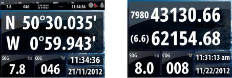
Position panels
By default, there is one position panel available showing GPS position.
If Loran is enabled as described on page 28, there will be two position panels. This is indicated with arrow symbols on left and right side of the panel.
You toggle between the panels by tapping the left or right side of the panel.
GPS position info |
Loran position info |
Data fields
Position in lat. and lon. (GPS) or as Loran GRI and station values
Time and date
SOG |
Speed over ground |
COG |
Course over ground |
Navigating with the Zeus Touch | Zeus Touch Operator Manual |
| 29 |
 Loading...